Train-Tech GS1 User manual

See our website, your local model shop or contact us for a free colour brochure
DCP Microdevelopments, Bryon Court, Bow Street, Great Ellingham, NR17 1JB, UK
Telephone 01953 457800 • email sales@dcpmicro.com • www.dcpexpress.com
www.Train-Tech.com
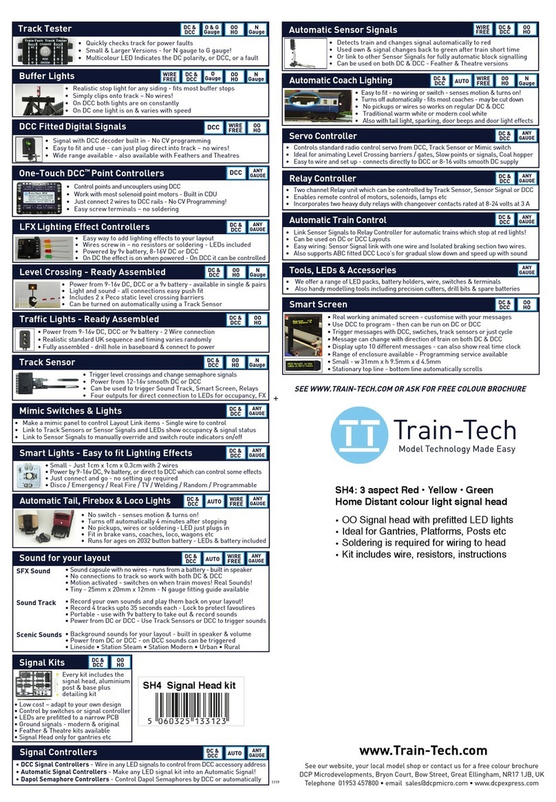
Train Tech overview - ask for free catalogue
Signal kits - OO/HO low cost easy to make signals for DC
Sensor Signals - easy automatic block signalling - DCC or DC
Smart Lights - small effects built in - DC/DCC - just 2 wires:
Arc welding • Emergency vehicle • TV • Fire effect •!Party disco
Automatic Coach Lights - motion - no pickups or wiring:
Older Warm White • Modern Cool White • Tail Light • Spark Arc
Automatic Tail Lights - motion - easy, no wires - lantern LED:
Flickering flame oil lamp • Modern Flashing • Constant light
Track Tester - quickly tests DC polarity or DCC - N-TT-HO-OO
SFX+ Sound capsules - no wires! - real trains - DC or DCC
Steam •!Diesel • DMU • Passenger coach • Shunted stock
Buffer Light - clip in lights for buffer stops - N or OO - DC/DCC
LFX Lighting effects - DC/DCC - screw terminals - with LEDs:
Home & Shop lighting • Welding •!Flashing Effects •!Fire
Traffic Lights - fully assembled - just connect to DC or DCC
Level Crossings - assembled - N & OO versions - DC / DCC
DCC fitted signals - slide in the track - easy one touch setup:
2 aspect • 3 aspect • 4 aspect • Dual head • Feathers • Theatre
DCC Point Controllers
DCC Signal Controllers
LEDs
Tools etc
COMPREHENSIVE CATALOGUE FREE ON REQUEST
www.train-tech.com
GS1 - Ground Signal
GS1 Red / White Ground Signal
•Modern & Original Stop light styles
•Easy mounting using cap supplied
• DCC controlled with built in decoder
•DC powered from 12-16V smooth DC
•Automatic operation by Track Sensor
•Control & indicate with Mimic switch
Signal Mounting cap
OO Gauge Ground Position
signal for both DCC and DC

GS1 Ground Signal
1"
Please handle carefully & read these instructions fully before installing!!
Contents list:
• GS1 Red-White Ground signal assembly
•Mounting cap: x 1 (2 part)
•Sample length of solid core wire 1/0.6mm
•Instruction guide
Introduction
This ground signal is an accurate OO scale representation of ground signals as seen on real
railways and they are usually found around fiddle and shunting yards. The two lower LED lights
can be set to display either modern Red-Red or original Red-White style for Stop.
The built in electronics includes a digital decoder for DCC control, an input for a Track Sensor to
control the signal automatically with train movement and another input for connection to a Train-
Tech Mimic switch which can control the signal, indicate signal status and if Track Sensors are
used also show train occupancy, all linked using a single wire.
It is beyond the scope of these instructions to explain exactly where to locate and use Ground
Position signals (sometimes called Shunt Signals), but there are plenty of good books on railway
signalling as well as many resources online.
Please handle it with extreme care - as with most precision scale models it is fragile!
Document Ref D779732/1 DP160318
Troubleshooting
This product is designed to be easy to fit and use but here are a few tips which may help should
you have problems following installation. Remember only wire and install with power turned OFF.
•Flickering lights when powered from DC?
Check that the DC is really smooth DC and not rough from a crudely rectified AC. Train-Tech offer
a low cost capacitor smoothing unit to convert rough DC to smooth DC called SM1 and also
Gaugemaster make a good quality 12V regulated and smooth mains power unit ideal for model
railway electronics, part No WM4.
•Intermittent automatic operation?
If using Track Sensors which are powered using the slide in track fingers check that they are
making good contact with the rails and that the sensor is close to but not touching the rail.
•Cannot program control by DCC?
This Ground Signal works on DCC Accessory addresses, not loco addresses, so check your
DCC controller can control DCC accessories and make sure the controller is set to Accessory
mode before you set up.
•Problems plugging in wires to the sockets?
The sockets fitted to the Ground Signals and Track Sensors are designed to be used with single
core wire 1/0.6mm gauge or similar, as per sample supplied (sometimes called ‘Bell Wire’). Do
not use stranded wire as this will not fit properly and stray strands may not go into the socket and
touch other contacts or components causing damage.

2
•Installing the Ground Signal
Firstly, before fitting or connecting your Ground Signal SWITCH OFF ALL POWER!
The Ground signal has sensitive electronics which may be permanently damaged if stray wires
touch components or connections. Please note that the circuitry under the signal head will run
slightly warm - this is normal.
The picture below shows you what the parts do and the instructions to show how to power and
control your Ground Signal are on the following pages - choose the appropriate page for your
power system & layout.
Mounting cap - 2 halves
Fits around light head post & locks everything
together once pushed into a 10mm hole in
baseboard - no glueing will be required
Note that it can be fitted at 2 different positions
to enable the head to be mounted at different
heights to allow space for a location board etc.
Ground Signal head
Pushbutton
Used to set up signal colour style and DCC
Connection sockets
Used to connect power and control wires to
the signal without need for any soldering!
Use single core solid wire such as 1/0.6mm.
Functions explained on following pages
Control Terminals
Inputs for Mimic Switch & Track Sensor
Power Terminals
Either 12-16V smooth DC or DCC from track
P
M

PP
M T
Circuitry
located here
Take care
not to
touch any
components
in this area
3
• Control and power by Digital DCC
This section shows how to power and control your ground signal using Digital DCC.
Most DCC controllers or PC based systems should be compatible as long as they are capable of
controlling DCC accessory addresses (as opposed to only DCC locomotive addresses).
You can power the signal easily with 2 wires connected from the nearest DCC supply (eg Track,
bus bar or controller output) and the bottom two connection sockets marked P on the signal.
Setup is easy using Train-Tech One Touch DCC; Just choose an accessory address on your
controller or PC, press the Learn button on the Crossing and finally send a direction or 1 or 2
command from your controller to set it up (commands vary between controllers - see instructions).
We recommend all signal connections are made using solid single core wire which simply plugs
into the sockets (not stranded wire as stray whiskers of wire can short to other components.)
Caution - Only make connections with ALL POWER OFF and ensure you never touch any
other metal terminals or components otherwise permanent damage will result.
Never use AC or any voltage over 16 volts DC - if in doubt check supply with a voltmeter.
Connect to the nearest DCC rails, DCC controller
output terminals or a DCC bus if you have one
POWER
One Touch DCC - easy setup
1) Wire your signal as below and turn the DCC power on
2) Choose a DCC accessory address for your ground
signal and select it on your controller
3) Press the Pushbutton to alternate between the style of
Stop signal lights you want - the LED lights will
alternately flash as follows:
Original Style: Stop = Red+White
Modern Style: Stop = Red+Red
Leave the signal flashing the style you choose to use
4) Send a direction command tor u/ 1 or 2 (the exact
command will depend on your controller - refer to your
controller instructions on using Accessory commands).
The signal will display Proceed (2 whites) and has set
your chosen address into the signal which you can now
control using the accessory address you set.
Tip If you choose the same address for your signal as
another signal or DCC controlled point they will change
together. Note that the tor u/ 1 or 2 command you
use to set it up always sets the signal to Proceed.
Pushbutton

4
12-16 Volts smooth DC
Signal Control Switch
Double-pole double-throw (DPDT)
(moving switch reverses polarity)
PP
M T
Circuitry
located here
Take care
not to
touch any
components
in this area
• Control and power by Analogue DC
This page shows how to power and control your Ground signal using traditional 12-16V smooth
DC - sometimes called analogue.
You can power and control this signal easily using just 2 wires from your smooth DC supply to the
bottom 2 connections marked P on the signal. By reversing the polarity, the signal will change its
state from Stop to Proceed. Using DC control, if the left hand P terminal is positive the signal will
show Stop (red), if the right hand terminal is positive it will show Proceed (2 whites).
You can reverse the polarity in several ways, but most conveniently using a DPDT (double pole
double throw) switch, such as the toggle switch in Train-Tech pack TS1.
We recommend connections are made using solid single core wire (bell wire) which simply plugs
into the sockets (not stranded wire as stray whiskers of wire can short to other components.).
A 1m sample is included but more can be bought from Train Tech (WP2/WP3) and most electrical
suppliers - it is sometimes called 1/0.6mm wire which means 1 core 0.6mm diameter.
Caution - Only make connections with ALL POWER OFF and ensure you never touch any
other metal terminals or components otherwise permanent damage will result.
Never use AC or any voltage over 16 volts DC - if in doubt check supply with a voltmeter.
POWER
Ground signal colour style
This signal can be set to display either the original
Red+White stop light or the modern Red+Red stop light.
1) Wire your signal as below, turn the DC power on and
using the switch change polarity so that the signal lights up
the two lower LED lights.
2) Press the Pushbutton on the signal to alternate between
the style of Stop lights you want to display - the bottom 2
LED lights will alternately display as follows:
Original Style: Red+White
Modern Style: Red+Red
Leave the signal showing the style you want to use
Pushbutton
Above is the schematic for a DPDT switch but
also represents the same wiring layout for the
connections on many toggle and slide switches

PP
M T
Circuitry
located here
Take care
not to
touch any
components
in this area
POWER
5
• Control using a Mimic Switch - powered from DC or DCC
•
As well as being controlled by Track Sensor, DC or DCC, your Ground signal can also be controlled
by a Train-Tech Mimic Switch. The Mimic Switch is connected to the signal using a single wire and
should be powered from the same power supply which can be DC or DCC. For details of how to
connect DC or DCC power and to set up the signal style see the relevant page in this manual.
The drawing below shows how to connect a mimic switch to the Ground signal using a single wire.
On a MS1 Toggle Mimic Switch the up position is Proceed and the lower position is for Stop - note
that the MS1 Mimic Switch takes priority over either DCC control or Track Sensor. The centre
position of the toggle switch allows the signal to be controlled by either DCC and/or Track Sensor.
On a MS2 Pushbutton Mimic you can change signal from Proceed to Stop by pressing the button.
As well as controlling the signal, either type of Mimic Switch or a ML1 Mimic Light also remotely
shows signal status and, if also using a Track Sensor, occupancy of the train.
Caution - Only make connections with ALL POWER OFF and ensure you never touch any
other metal terminals or components otherwise permanent damage will result.
Never use AC or any voltage over 16 volts DC - if in doubt check supply with a voltmeter.
Power input - connect to DCC or 12 to 16 volts smooth DC
Mimic Switch
(MS1 shown)
Mimic Switch - functions
Connections
The Mimic switch has 3 terminals;
2 for the DC or DCC power supply and 1
which connects to the signal.
Controlling signal
You can use a Mimic Switch to manually
control the Ground Signal:
MS1 Toggle Mimic Switch
Toggle up - Proceed (Signal White)
Toggle down - Stop (Signal Red)
MS2 Pushbutton Mimic Switch
Push to alternate signal between Proceed
and Stop.
Signal status LED indicator (top LED)
Mimic Switch and Mimic Light has 2 LEDs
to display the status of the signal and
occupancy if a Track Sensor is connected.
Green - Proceed (Signal White)
Red - Stop (Signal Red)
Occupancy LED indicator
(if a Track Sensor is also connected)
The lower LED flashes when the train
passes over the Track sensor to show
occupancy and if 2 Track Sensors are
used this LED will remain on whilst the
train is located between the Sensors.
Top LED
Signal status
Lower LED
Occupancy

PP
M T
Circuitry
located here
Take care
not to
touch any
components
in this area
6
• Automatic control using a Single Track Sensor
As well as controlling the Ground Signal manually by a switch or DCC you can also control it
automatically using a Track Sensor, so that when a Train approaches the signal changes to show
proceed until the train has passed, then after 7 seconds changes back (see the following page to
see how to connect an additional track sensor to change the signal back instead of time).
The Track sensor must be powered by the same power as the Ground Signal which can either be
Digital DCC or Analogue 12-16 Volts smooth DC and just a single wire links from the middle
socket of the Track Sensor to the right hand socket of the Ground Signal marked T - see below.
(Note Sensor Signals also perform like Track Sensors so can also be used to control GS Signals)
Approach
Track sensor
Direction
of Trains
POWER
Power both the track sensor and
the Ground Signal from the same
power supply; either DCC from
the track or wire to 12-16V DC
Power by sliding sensor into track - for DCC
If using DCC you
can power the
sensor from the
track by sliding
these two ‘fingers’
under the rails into
the slots in some
types of track, like
a power clip.
ensure good
connections!
Track Sensor or
Sensor Signal
To power using
DC or DCC solder
2 wires into the
holes shown
Power by wiring to sensor - for DC or DCC
Track Sensor or
Sensor Signal
Cut off the two fingers
with sharp cutters
where marked - - -
Powering the Track sensor
If used on DCC a Track Sensor can either be clipped straight into some types track in the power
clip slots (eg Hornby or Bachmann) but if not the slide-in fingers can be cut off and the two
connections shown wired to either DCC or 12-16 Volts DC - see below.
POWER
Automatic operation
The signal will change to proceed (two white
lights) as soon as a Train passes over the
Approach Track sensor. When the train has
completely passed the signal will change
back.
Be sure to locate the Track sensor a suitable
distance from the signal so that it changes
as a Train approaches.
Signal Style
This signal can be set to
display the modern red-red or
traditional of red-white style
stop lights. To set the colour
style of your signal refer to the
relevant page for DCC power
(page 3) or DC (page 4).

7
• Automatic control using Two Track Sensors
The previous page shows how a Track Sensor can be fitted to change the signal to proceed as
the train goes past it, then after fixed time the signal will go back to stop.
Instead of the signal changing back a certain amount of time after the train has passed, you can
add another Sensor to only change it back when the train passes the second Track Sensor.
A single wire is all that is needed to link the additional Track Sensor to the first as shown below.
Both Track sensors must be powered by the same power as the Ground Signal which can either
be Digital DCC or Analogue 12-16 Volts smooth DC. A single wire links from the middle socket of
the first Track Sensor to the right hand socket of the Ground Signal marked T - see below.
(Note Sensor Signals also perform like Track Sensors so can also be used to control GS Signals)
PP
M T
Circuitry
located here
Take care
not to
touch any
components
in this area
Direction
of Trains
POWER
Power both the track sensor and
the Ground Signal from the same
power supply; either DCC from
the track or wire to 12-16V DC
POWER
Power by sliding sensor into track - for DCC
If using DCC you
can power the
sensor from the
track by sliding
these two ‘fingers’
under the rails into
the slots in some
types of track, like
a power clip.
ensure good
connections!
Track Sensor or
Sensor Signal
To power using
DC or DCC solder
2 wires into the
holes shown
Power by wiring to sensor - for DC or DCC
Track Sensor or
Sensor Signal
Cut off the two fingers
with sharp cutters
where marked - - -
Powering the Track sensor
If used on DCC a Track Sensor can either be clipped straight into some types track in the power
clip slots (eg Hornby or Bachmann) but if not the slide-in fingers can be cut off and the two
connections shown wired to either DCC or 12-16 Volts DC - see below.
Automatic operation
The signal will change to proceed (two white
lights) as soon as a Train passes over the first
(Approach) Track sensor. When the train has
completely passed the second (Return) Track
Sensor the signal will change back.
Be sure to locate the Track sensors suitable
distances from the signal so that it changes as
a Train approaches and back after it passes
the second Track Sensor.
Approach
Track sensor
Return
Track sensor
Signal Style
This signal can be set to
display the modern red-red or
traditional of red-white style
stop lights. To set the colour
style of your signal refer to the
relevant page for DCC power
(page 3) or DC (page 4).
Other Train-Tech Toy manuals

Train-Tech
Train-Tech SH4 User manual

Train-Tech
Train-Tech SH6 User manual

Train-Tech
Train-Tech SFX 10+ User manual

Train-Tech
Train-Tech SFX70+ User manual

Train-Tech
Train-Tech SFX20+ User manual

Train-Tech
Train-Tech SFX 11+ User manual

Train-Tech
Train-Tech CL2 User manual

Train-Tech
Train-Tech SFX User manual

Train-Tech
Train-Tech LK1 User manual

Train-Tech
Train-Tech Sensor Signals User manual