Page 8
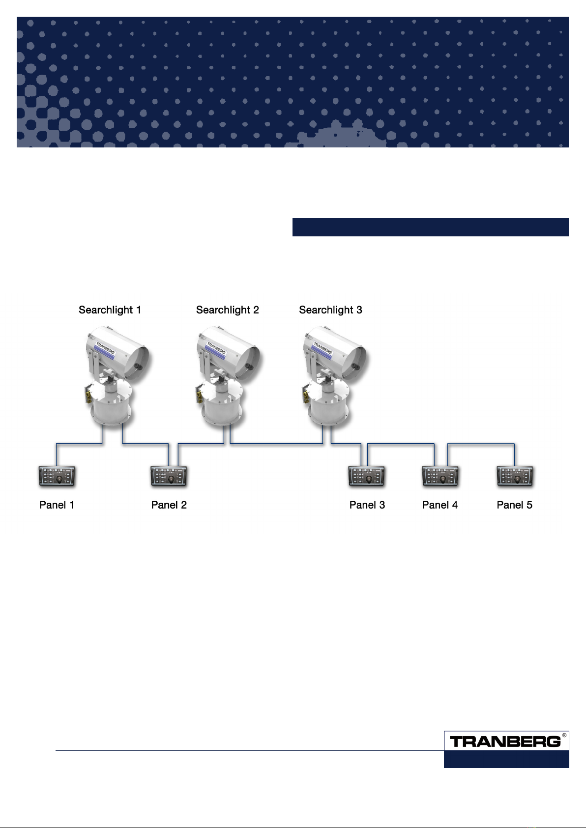
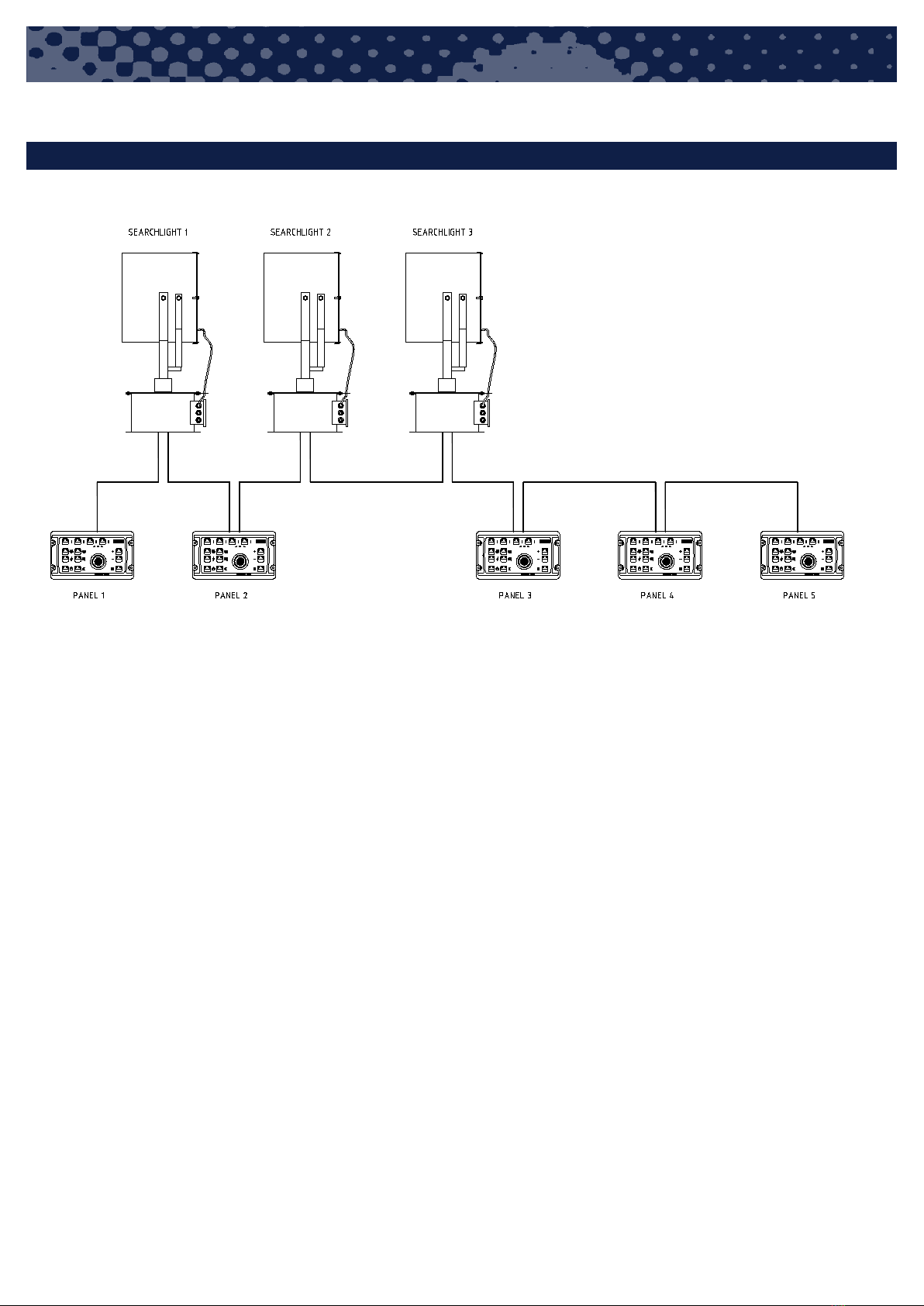
COMMANDER SEARCHLIGHT - NETWORK & CONFIGURATION MANUAL
4.1 IDENTIFYING THE MASTER PANEL
For the following special procedures, the master panel need to be
identified.
The master panel can be recognized by the yellow indicator in the
power button. When you turn off power by pressing this button, the
yellow indicator will be continuously lit in the master panel. It will blink
slowly (1 sec. on, 1 sec off) on a slave panel.
4.2 RE-SCAN OF NODES CONNECTED TO THE BUS
If necessary, the master panel can do a bus scan when powered up
using the following procedure:
(Note: Do not operate or use any panels or searchlights during this
procedure. Ensure that all are powered up.)
1. Turn off the master panel using the power button. Release the but-
ton. The backlight will turn off.
2. Press and hold the power button for at least 5 seconds.
3. While holding the power button, press and release the second se-
lect button (marked ‘2/6’ (2613) or ‘B’ (2614) ). (Repeat if neces-
sary, until backlight turns on).
4. The panel backlight will now turn on, and it will start the scanning
of the bus (it takes a couple of seconds).
5. Release the power button.
6. When the scan process is finished, the panel will show which
searchlights are present on the bus by fast flashing the corre-
sponding leds on the select buttons (upper row).
7. Turn on the panel by using the power button as usual.
8. Repeat the procedure if necessary.
4.3 ALTERNATIVE RE-SCAN PROCEDURE
FOR PANELS DELIVERED FROM APRIL 2009 AND ONWARDS:
If necessary, the master panel can do a bus scan when powered up
using the following procedure: A panel can do both this alternate
re-scan procedure as well as the previous procedure (ch. 5.1).
(Note: Do not operate or use any panels or searchlights during this
procedure. Ensure that all are powered up.)
1. Set all panels to standby (“turn off”) by using the on/stdby button.
The backlight will turn off. Locate the master panel (see ch. 3.2),
and turn it on again.
2. Press and hold both speed buttons (‘fast’ and ‘slow’) for at least
5 seconds.
3. On the 2613 and 2614 panels, the indicators in the ‘searchlight
select’ buttons will start flashing in sequence. On the 2612 panels,
the indicators in the speed buttons will flash in sequence. Release
the speed buttons.
4. The sequential flashing will last for a couple of seconds, as long as
the scanning of the bus is performed. When the flashing is finished,
the system is ready for use.
5. Repeat the procedure if necessary.
4.4 RESET OF SEARCHLIGHTS
1. Remove power (230VAC) to the searchlight (motor unit), wait for
approx. 10 sec, and reconnect the power. (It is not necessary to
disconnect the xenon power supply). If several searchlights need
to be reset, repeat this for each searchlight before commencing
to step
2. Do a re-scan from the master panel. Alternatively, remove and re-
apply power (24VDC) to the panels, either all or at least the master
panel. The searchlight will now move to the right and upwards to
find the end positions, and back to center. If necessary, watch the
searchlight at this stage to verify the movement.
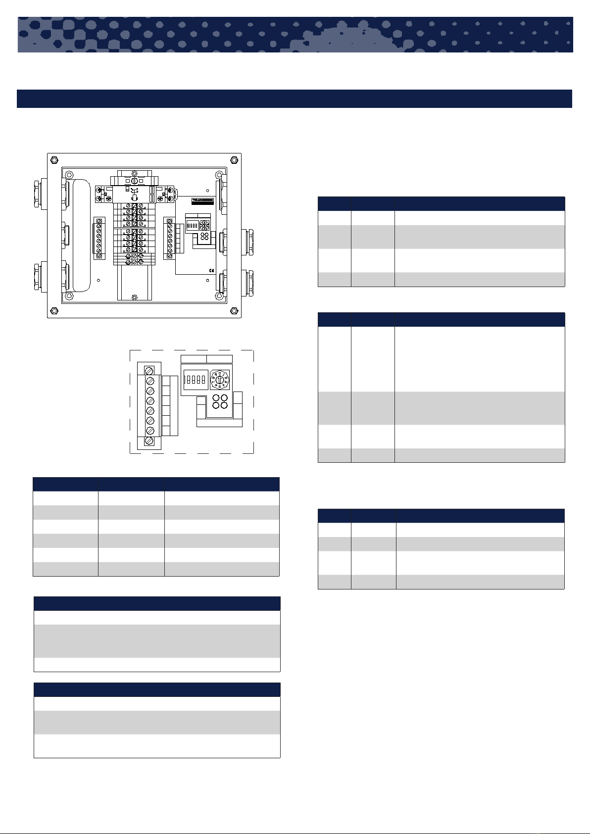
4.5 RECALIBRATE END LIMITS ON SEARCHLIGHTS
1. Open the searchlight junction box and set DIP-switch no. 1 to ON.
2. Remove power (230VAC) to the searchlight (motor unit), wait for
approx. 10 sec, and reconnect the power. (It is not necessary to
disconnect the xenon power supply). If several searchlights need
to be reset, repeat this for each searchlight before commencing
to step 3.
3. Do a re-scan from the master panel. Alternatively, remove and re-
apply power (24VDC) to the panels, either all or at least the master
panel. The searchlight will now do a complete movement up – right
– left – center/down to find the end limit positions, and back to
center. If necessary, watch the searchlight at this stage to verify
the movement.
4. Set the DIP-switch no. 1 back to OFF and close the junction box.
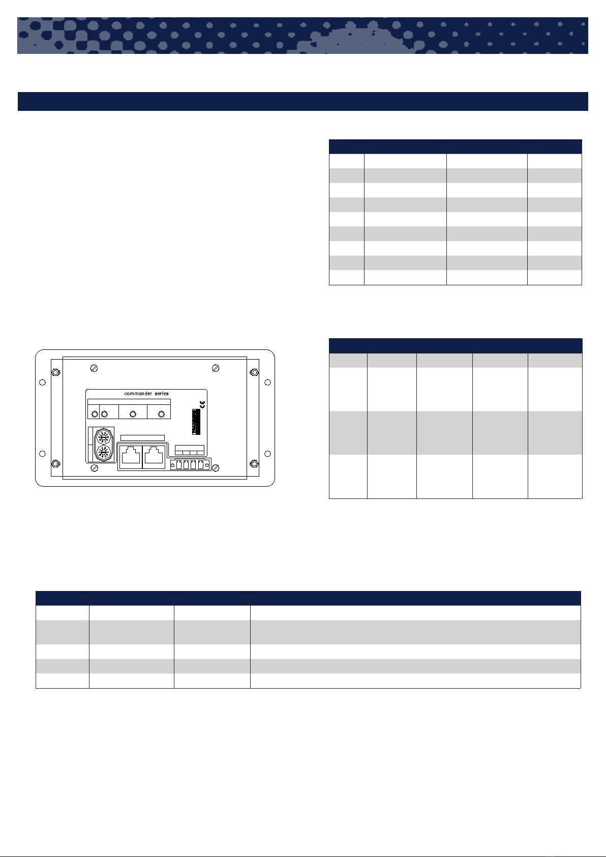
4.6 CHANGING ADDRESS ON A SEARCHLIGHT
PREPARATION:
1. Identify the master panel. Unmount the master pan-
el, so as to get access to the rotary swiches on the rear.
IMPORTANT: Make a note of the settings of the switches
2. Disconnect the power supply to all the searchlights. (Leave the
power supply to the panels connected).
PROCEDURE:
3. Connect the power supply to the searchlight whose
address shall be changed.
4. Turn off the master panel using the power button. Release the but-
ton. The backlight will turn off.
5. Set the rotary switch labeled ”N/A” on the rear, set it to
one lower than the new address of the searchlight (address
minus 1, e.g. set to ‘1’ if the searchlight is to be set to
address ‘2’, i.e. respond to the first press of button ‘2/6’).
6. Press and hold the power button for at least 5 seconds. While
holding the power button, push the button marked ”3/7” (a short
normal push and release). This button can alternatively be pushed
several times, until the panel backlight is lit. When the backligth
is lit, release the power button. The panel will now send a special
message to the searchlight.
7. Check the indicators in the searchlight select buttons (”1/5”, ”2/6”,
”3/7” and ”4/8”). After approx. 5 – 10 sec. one of them will flash
fast (2 times pr. sec) to show the new address of the searchlight.
4 SPECIAL PROCEDURES