manuals.online logo
Brands
  1. Home
  2. •
  3. Brands
  4. •
  5. Trane
  6. •
  7. Air Handler
  8. •
  9. Trane 7 Series Installation and operating instructions

Trane 7 Series Installation and operating instructions

Other manuals for 7 Series

1

Other Trane Air Handler manuals

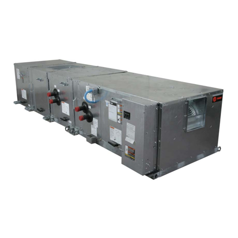
Trane Climate Changer T Series Owner's manual

Trane

Trane Climate Changer T Series Owner's manual

Trane CLCP Euro 25 Owner's manual

Trane

Trane CLCP Euro 25 Owner's manual

Trane BMTX BCU User manual

Trane

Trane BMTX BCU User manual

Trane IntelliPak WEHE Series Installation and operating instructions
Trane

Trane IntelliPak WEHE Series Installation and operating instructions
Trane Performance Climate Changer Installation and operating instructions
Trane

Trane Performance Climate Changer Installation and operating instructions

Trane A4AH6E19A1B30B User manual

Trane

Trane A4AH6E19A1B30B User manual

Trane 4YCC4024E1060 User manual

Trane

Trane 4YCC4024E1060 User manual

Trane 4PXFH001AC3HHA Assembly instructions

Trane

Trane 4PXFH001AC3HHA Assembly instructions

Trane RRU120 D B Series Installation and operating instructions

Trane

Trane RRU120 D B Series Installation and operating instructions

Trane GAF2A0A36S31EE Assembly instructions

Trane

Trane GAF2A0A36S31EE Assembly instructions

Trane BAYAHEMIKIT001A User manual

Trane

Trane BAYAHEMIKIT001A User manual

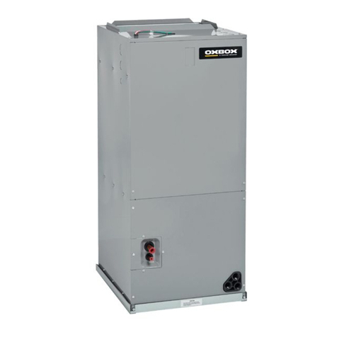
Trane Oxbox J4AH4P24B1A00AA User manual

Trane

Trane Oxbox J4AH4P24B1A00AA User manual

Trane Climate Changer TCFS Installation guide

Trane

Trane Climate Changer TCFS Installation guide

Trane LPC User manual

Trane

Trane LPC User manual

Trane CCEB Owner's manual

Trane

Trane CCEB Owner's manual

Trane 2TEE3C31A1000A Assembly instructions

Trane

Trane 2TEE3C31A1000A Assembly instructions

Trane 4PXFH001BC3HHA Assembly instructions

Trane

Trane 4PXFH001BC3HHA Assembly instructions

Trane CWS 02-2P Quick start guide

Trane

Trane CWS 02-2P Quick start guide

Trane CDQ Operating and safety instructions

Trane

Trane CDQ Operating and safety instructions

Trane 2TEE3F39A1000A Assembly instructions

Trane

Trane 2TEE3F39A1000A Assembly instructions

Trane CSAA Installation and operating instructions

Trane

Trane CSAA Installation and operating instructions

Trane TRANE Quantum CLCPEuro Operating and safety instructions

Trane

Trane TRANE Quantum CLCPEuro Operating and safety instructions

Trane AHUMD200A 00BA Series Assembly instructions

Trane

Trane AHUMD200A 00BA Series Assembly instructions

Trane GAM5 Series Assembly instructions

Trane

Trane GAM5 Series Assembly instructions

Popular Air Handler manuals by other brands

Vents VUT 270 V5B EC A14 user manual

Vents

Vents VUT 270 V5B EC A14 user manual

Armstrong Air BCE7S Series installation instructions

Armstrong Air

Armstrong Air BCE7S Series installation instructions

Klimor EVO-S Operation and maintenance manual

Klimor

Klimor EVO-S Operation and maintenance manual

Salda SMARTY XP MOUNTING AND INSTALLATION INSTRUCTION

Salda

Salda SMARTY XP MOUNTING AND INSTALLATION INSTRUCTION

BLAUBERG KOMFORT Roto EC S400 user manual

BLAUBERG

BLAUBERG KOMFORT Roto EC S400 user manual

Trenton TPLP Series installation instructions

Trenton

Trenton TPLP Series installation instructions

Daikin DV PTC 14 Series installation instructions

Daikin

Daikin DV PTC 14 Series installation instructions

Haier HB2400VA1M20 Installation & operation manual

Haier

Haier HB2400VA1M20 Installation & operation manual

Webasto BlueCool A-Series operating instructions

Webasto

Webasto BlueCool A-Series operating instructions

RDZ DA 701 Technical installation manual

RDZ

RDZ DA 701 Technical installation manual

Carrier 39T Installation, Start-Up and Service Instructions

Carrier

Carrier 39T Installation, Start-Up and Service Instructions

Armstrong Air BCE5V Series installation instructions

Armstrong Air

Armstrong Air BCE5V Series installation instructions

Carrier 40MBDAQ Service manual

Carrier

Carrier 40MBDAQ Service manual

TemperZone Econex Pro OPA 1410RLTM4FPQD Installation & maintenance

TemperZone

TemperZone Econex Pro OPA 1410RLTM4FPQD Installation & maintenance

RDZ WHR 200 Technical installation manual

RDZ

RDZ WHR 200 Technical installation manual

AAON H3 Series Installation operation & maintenance

AAON

AAON H3 Series Installation operation & maintenance

Lennox VEOA042N432U Installation & operation instructions

Lennox

Lennox VEOA042N432U Installation & operation instructions

Kemper CleanAirTower operating manual

Kemper

Kemper CleanAirTower operating manual

manuals.online logo
manuals.online logoBrands
  • About & Mission
  • Contact us
  • Privacy Policy
  • Terms and Conditions

Copyright 2025 Manuals.Online. All Rights Reserved.

Page 1
INSTALLER'S GUIDE ADDENDUM
Field wiring
Yellow
Blue
SPDT Relay
w/24 VAC Coil
NO
NC
Red
Yellow
Orange
Blue
B
W
G
Y1
Y2
Y1
R
O
O
O
R
B
B
YI
W1
YO YO
Y2
BK
G
W2
W3
(In)
(Out)
Green
Comfort Control *
Series 7 Air Handler
Air Conditioner
Single Stage Cooling
Neatly bundle all low voltage
wires behind the service
valve cover as shown.
Notes:
* Heat Pump thermostat is required. Must be set in Heat Pump configuration.
1. It is recommend to use the enhanced mode blower delay profile. See the
Installer’s Guide for S2-3 and S2-4 settings.
2. Wiring must be made as shown for proper operation. Shown in de-energized position
Hydronic
Control
Typical Boiler
Wiring
B
T
T
Comfort Control
Heat Pump
Series 7 Air Handler
Neatly bundle all low voltage
wires behind the service
valve cover as shown.
Field wiring
Yellow
Blue
Black
(X2)
Red
Orange
Red
Yellow
Orange
Green
White
Blue
B
Y2
B - Blue
W
X2
G
Y1
Y1 - Yellow
R
O
O
R
B
YI
Y2
W1
YO
BK
G
W2
W3
R - Red
O - Orange
(In)
(Out)
W1 - White
Single Stage Heat Pump
Notes:
1. Emergency heat mode only delivers 50% airflow.
2. Hydronic heat is designed for supplemental heat during
compressor operation.
3. It is recommend to use the enhanced mode blower delay
profile. See the Installer’s Guide for S2-3 and S2-4 settings.
4. Wiring must be made as shown for proper operation.
Hydronic
Control
Typical Boiler
Wiring
B
W
T
T
Field Wiring Diagrams for Hydronic Coil with Series 7 Air Handlers
18-GJ21D1-1A_Addendum
Notes:
1. For Family 7 air handlers, a relay and Heat Pump thermostat are required for cooling only application. For Heat Pump OD applications the relay is not required.
2. For Heat Pump systems, the hydronic coil is designed for Supplemental Heat. It is not designed for Emergency Heat.
Page 2
INSTALLER'S GUIDE ADDENDUM
Comfort Control *
Series 7 Air Handler
Air Conditioner
Two Stage Cooling
Neatly bundle all low voltage
wires behind the service
valve cover as shown.
Field wiring
Yellow/Black
Blue
Red
Yellow
Green
Brown
Orange
Blue
B
W
G
Y1
Y2
R
O
O
R
B
YI
W1
YO
Y2
BK
G
W2
W3
(In)
SPDT Relay
w/24 VAC Coil
NO
NC
Y1
OB
YO
(Out)
Shown in de-energized position
Yellow
/Red
Brown
Notes:
* Heat Pump thermostat is required. Must be set in Heat Pump configuration.
1. It is recommend to use the enhanced mode blower delay profile. See the
Installer’s Guide for S2-3 and S2-4 settings.
2. Wiring must be made as shown for proper operation.
Hydronic
Control
Typical Boiler
Wiring
B
T
T
Comfort Control
Heat Pump
Series 7 Air Handler
Neatly bundle all low voltage
wires behind the service
valve cover as shown.
Field wiring
Yellow
Yellow/Red
Blue
Black
(X2)
Red
Orange
Red
Yellow
Brown
Orange
Green
White
Blue
B
Y2
B - Blue
W
X2
G
Y1
Y1 - Yellow
Y2 - Brown
R
O
O
R
B
YI
Y2
W1
YO
BK
G
W2
W3
R - Red
O - Orange
(In)
(Out)
W1 - White
Two Stage Heat Pump
Notes:
1. Emergency heat mode only delivers 50% airflow.
2. Hydronic heat is designed for supplemental heat during
compressor operation.
3. It is recommend to use the enhanced mode blower delay
profile. See the Installer’s Guide for S2-3 and S2-4 settings.
4. Wiring must be made as shown for proper operation.
Hydronic
Control
Typical Boiler
Wiring
B
W
T
T