manuals.online logo
Brands
  1. Home
  2. •
  3. Brands
  4. •
  5. Trane
  6. •
  7. Recording Equipment
  8. •
  9. Trane X13790901030 User manual

Trane X13790901030 User manual

SAFETY WARNING
Only qualified personnel should install and service the equipment. The installation,
starting up, and servicing of heating, ventilating, and air-conditioning equipment can
be hazardous and requires specific knowledge and training. Improperly installed,
adjusted or altered equipment by an unqualified person could result in death or
serious injury. When working on the equipment, observe all precautions in the
literature and on the tags, stickers, and labels that are attached to the equipment.
© 2020 Trane
2
1
345
Installation Instructions
Air-Fi® Wireless
Communications Interface (WCI)
Model Number: X13790901030, X13790902030, X13790903030,
X13790904030, X13790941030
Set Addresses
WCI WCI
GRP NET
GRP
NET
GRP NET
21 21
21
WCI
WCI WCI
GRP NET
GRP
NET
GRP NET
22 22
22
WCI
SC - 2
Device Device Device Device
SC - 1
GRP NET
11
WCI
GRP NET
12
WCI
Device Device
WCI WCI
GRP NET
NET
111
WCI WCI
GRP NET
GRP
NET
12 12
Device Device
GRP
1
1
2
3
4
5
6
7
8
9
0
NETGRP
1
2
3
4
5
6
7
8
9
0
For detailed information and procedures, refer to the
following documents:
• Air-Fi®Wireless Installation, Operation, and
Maintenance (BAS-SVX40*)
•Air-Fi®Wireless Network Design Best Practices
Guide (BAS-SVX55*)
June 2020 BAS-SVN038C-EN
Connecting the Wiring Harness to the WCI
Gray = LINK–
Blue = LINK+
Red = +24VDC/VAC
Black =
WARNING Indicates a potentially hazardous situation which,
if not avoided, could result in death or serious
injury.
CAUTION Indicates a potentially hazardous situation which,
if not avoided, could result in minor or moderate
injury. It could also be used to alert against unsafe
NOTICE Indicates a situation that could result in
equipment or property-damage only accidents.
X39641361001
WCI MSTP
VAC
24
BI
1
BI
2
BI
3
LINK IMC
+
24
VDC
IM
C
Jumper
LINK -
LINK +
+24 Vdc
WCI
BCI-I
+24 VDC/VAC
Use a PM014 with Tracer SC with 1 or more
wireless networks, or Tracer SC+ when needed
to stay within IMC power budget.
PM014
WCI wiring
LINK +
LINK –
+ 24VDC
IMC– IMC+ Ground 24 Vdc
Power OFF
Device
+
24
VDC
IM
C
LINK IMC
LINK+
LINK–
+24 Vdc
WCI
UC
Hazardous voltage!
Disconnect all electric power, including remote disconnects before servicing.
Follow proper lockout/tagout procedures to ensure that power cannot be
inadvertently energized. Failure to disconnect power before servicing could
result in death or serious injury.
Tracer SC/SC+
UC 210/400/600
BCI-I (IntelliPak/CSC) BCI-R (ReliaTel™: Voyager™, Precedent™, and Odyssey™)
WCI as Repeater
Connect WCI Wires to Controller
Note: It is normal for the
Repeater DIAG LED to flash.
Note: Field-supplied.
Connect both 2-connector screw
terminal blocks to either of the
IMC terminals on the PM014.
Power ON Device
Note: If all devices
cannot be powered on at
the same time, the best
practice is to power them
on in the following order:
1. All WCIs
2. All unit controllers:
UC210, UC400,
UC600, BCI-I, BCI-R
3. All Tracer SCs
4. All WCSs
Tracer SC+
WCI Wiring
Tracer SC+ when IMC power budget allows
©2020 Trane
Trane has a policy of continuous product and product data improvement and reserves the
right to change design and specifications without notice. We are committed to using
environmentally conscious print practices.
Trane - by Trane Technologies (NYSE: TT), a global climate innovator - creates
comfortable, energy efficient indoor environments for commercial and residential
applications. For more information, please visit trane.com or tranetechnologies.com.
7
6
89
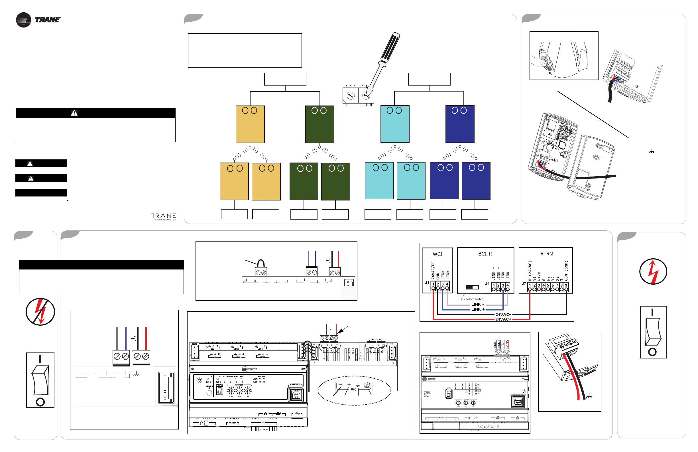
If a Tracer SC is present when the WCI is powered:
• The WCI that is wired to Tracer SC becomes network
coordinator and network formation is initiated.
• The network automatically opens and remains open for
60 minutes.
• The LEDs illuminate on the network coordinator as
shown. See Table 1 for details.
NWK, CRD, and
OPEN NET on
steady
If no Tracer SC is present when the WCI is powered:
1. Identify a centrally located WCI to be the network coordinator.
2. Manually open the network by pressing the Start button for 5 seconds on the
WCI that is to be network coordinator. The WCI becomes network coordinator
and network formation is initiated.
3. Observe the LEDs on the network coordinator. See Table 1 for details.
Press START/JOIN
for 5 seconds
WCI
Coordinator WCI
NWK, CRD, and
OPEN NET on
steady
Identifying the Network Coordinator (One per Network) and Initiating Network Formation The Network Forms
The NWK LED illuminates on every WCI that joins the network.
Coordinator WCI
1
Hr.
Device
WCI
NWK
WCI
NWK
WCI
NWK
WCI
NWK
Device DeviceDevice
Notes:
• Network automatically stays open 1 hr. After
each WCI joins, the 1 hr. timer starts over. If time
expires, press OPEN NET to re-open the network.
• The coordinator opens all WCIs in the network. A
member WCI can only open itself for 10 minutes.
Firmware Requirements for Devices in an Air-Fi®
Wireless Network
This table lists the minimum firmware levels required to allow devices to
participate in an Air-Fi®Wireless network.
Table 2. Minimum firmware levels required
Device
Minimum firmware level required for devices on
a Air-Fi®Wireless network
One or no WCSs
Multiple WCSs or
an RH sensor module
(WCS-SH)
Tracer SC V3.6.xxx N/A
UC210 All versions V2.00.xxx.mod
UC400 V6.00.xxx.mod V8.00.xxx.mod
UC600 V4.00.xxx.mod V5.00.xxx.mod
BCI-I V25.00.xxx.mod V28.00.xxx.mod
BCI-R V5.02.xxx.mod V6.00.xxx.mod
RTRM V12 or higher (requires physical
board replacement) N/A
Tracer TU V8.2 V8.6
TU Adapter V1.00.xxx.mod N/A
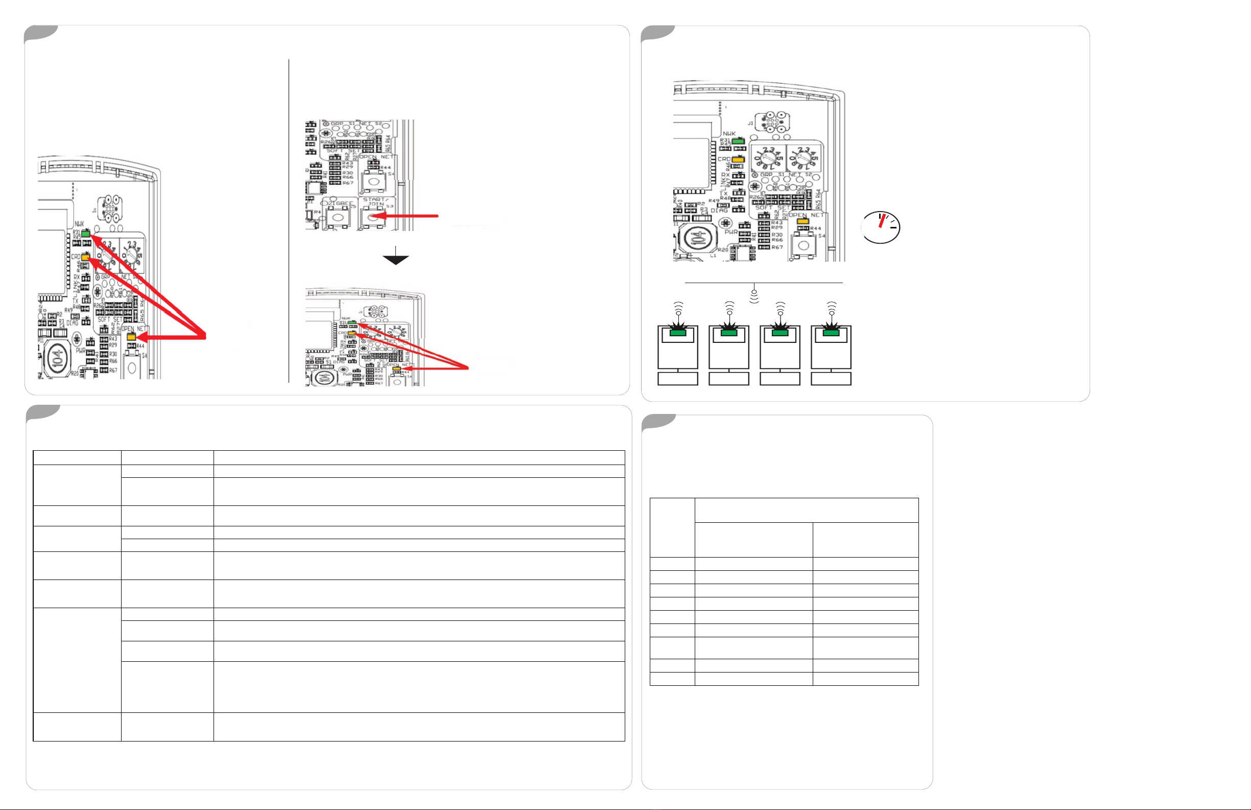
LED Identification and Interpretation
Table 1. LED identification and interpretation
LED LED activity Indicates
Network LED (green)
NWK
On solid WCI is a network member.
Flashes for 10 seconds
every 2.5 minutes. WCI is not a member of a network
The WCI will join a network when the NWK LED is flashing. If there is an open network nearby with the same rotary settings
and the WCI joins the network, the NWK LED turns on solid and then the OPEN LED turns on solid.
Coordinator LED (yellow)
CRD On solid WCI is network coordinator
Open Net LED (yellow)
OPEN NET
On solid Network is open for joining
Off Network is closed for joining
Reception LED (yellow)
RX LINK
Flashes(a)
On(b)
Off(c)
(a)LED will flash steady (about 3 flashes per second) on WCI that was built prior to 2019.
(b)LED will appear to be on steady for WCI built 2019 and after. Will appear dim and flicker occasionally according to how much data is passing.
(c) LED is off for all WCI.
Data received
Data received
No data received
Transmission LED (green)
TX LINK
Flashes(a)
On(b)
Off(c)
Data transmitted
Data transmitted
No data transmitted
Diagnostic LED (red)
DIAG(d)
(d)If more than one condition is present, the priority is in the order listed.
Off Normal operation
Flashes (½ second on, ½
second off repeating) Hardware failure or failed re-flash of a radio.
Corrective action: Replace WCI
Triple flash pattern. Failed to join network. Occurs for 30 seconds after failing to join a network. Will continue this pattern until successful join.
Corrective Action: Insure network is formed and open, then allow time for WCI to join on its own.
Double flash pattern
• Normal for a repeater.
• WCI lost IMC communication to the UC/BCI/Tracer SC/SC+.
Corrective action: Check IMC wiring, then cycle power to the controller/WCI to establish communication.
• WCI was not configured correctly. (WCI did not get BACnet ID from UC/BCI/SC/SC+, and/or WCI did not get rotary address
from the UC/BCI/SC/ SC+.)
Corrective Action: Cycle power to the controller/WCI.
Power LED (green)
PWR
On solid
Off WCI has power.
WCI does not have power.
Corrective Action: Check WCI power wiring for 24v DC or AC.
BAS-SVN038C-EN 19 Jun 2020
Supersedes BAS-SVN038B-EN (May 2019)

This manual suits for next models

3

Other Trane Recording Equipment manuals

Trane BACnet C175218460010 User manual

Trane

Trane BACnet C175218460010 User manual

Trane X13790901010 Installation and operating instructions

Trane

Trane X13790901010 Installation and operating instructions

Trane TCI-3 User manual

Trane

Trane TCI-3 User manual

Trane BACnet BCI-R Quick setup guide

Trane

Trane BACnet BCI-R Quick setup guide

Trane BCI-I Quick setup guide

Trane

Trane BCI-I Quick setup guide

Popular Recording Equipment manuals by other brands

iSimple PXAUX owner's manual

iSimple

iSimple PXAUX owner's manual

Ude GD-36 manual

Ude

Ude GD-36 manual

Pioneer PDR-L77 Service manual

Pioneer

Pioneer PDR-L77 Service manual

Apex Digital Argos user manual

Apex Digital

Apex Digital Argos user manual

Akai Riff-o-Matic U40 Operator's manual

Akai

Akai Riff-o-Matic U40 Operator's manual

Roland MKS-100 owner's manual

Roland

Roland MKS-100 owner's manual

ONTRAK ADU208 user manual

ONTRAK

ONTRAK ADU208 user manual

Comelit 3063U Technical manual

Comelit

Comelit 3063U Technical manual

Lowell SEQ-8 manual

Lowell

Lowell SEQ-8 manual

Parker 8903/IM Technical manual

Parker

Parker 8903/IM Technical manual

Rane DEQ 60L Operator's manual

Rane

Rane DEQ 60L Operator's manual

dbx ProVocal user manual

dbx

dbx ProVocal user manual

Strymon COMPADRE quick start guide

Strymon

Strymon COMPADRE quick start guide

Arturia FARFISA V user manual

Arturia

Arturia FARFISA V user manual

Korg Electribe ESX-1 owner's manual

Korg

Korg Electribe ESX-1 owner's manual

M2SYNTH BP VCF 113 Assembly instructions

M2SYNTH

M2SYNTH BP VCF 113 Assembly instructions

DOREMIDI MTC-20 instructions

DOREMIDI

DOREMIDI MTC-20 instructions

HP 10314D user guide

HP

HP 10314D user guide

manuals.online logo
manuals.online logoBrands
  • About & Mission
  • Contact us
  • Privacy Policy
  • Terms and Conditions

Copyright 2025 Manuals.Online. All Rights Reserved.