Trans-Cal SSD120-N-RS5 Quick start guide
Trans-Cal Industries, Inc.
Model SSD120-(XX)N-RS5
&
Model SSD120-(XX)NE-RS5
(Includes Mod. 1 Data)
All Solid-State
Altitude Encoder/Digitizer
Owner/Installation Manual
FAA TSO-C88a Approved
EASA ETSO-C88a Approved
Trans-Cal Industries, Inc.
Van Nuys Airport
16141 Cohasset Street
Van Nuys, CA 91406-2908
(818) 787-1221 (800) 423-2913 fax (818) 787-8916
www.trans-cal.com
22 June 2012 Document Number: 882204 Rev. C

Page 2 of 57
Copyright
This document may not be reproduced, transmitted, or copied in any form without the prior written consent of
Trans-Cal Industries, Inc. The data contained herein is subject to change without notice. Trans-Cal Industries
hereby grants permission to download one copy of this manual and any subsequent revision, provided that
electronic or printed copy contains this complete copyright notice. Trans-Cal Industries explicitly prohibits any
unauthorized commercial distribution of this manual or any revision thereto.
Limitations Please Note:
It is the responsibility of the installer of this equipment, within a specified type or class of aircraft, to determine that
the aircraft operating conditions are within TSO or ETSO standards. DO-160E lightning induced transient
susceptibility tests were not conducted on this device and it is the responsibility of the installing agency to
substantiate compliance with FAR25.1316. Advisory Circular AC20-136A provides guidance related to the
protection of aircraft electrical systems from the effects of lightning.
© 2012 by Trans-Cal Industries, Inc.
16141 Cohasset Street
Van Nuys, CA 91406
818/787-1221
800/423-2913 x400 Tech Support
FAX 818/787-8916
E-Mail: support@trans-cal.com
www.trans-cal.com
What’s in the Box:
Qty. Part Number Description
1 ea. SSD120-(XX)N-RS5 Altitude Digitizer with five RS232 Outputs
1 ea. 882204 Owner/Installation Manual
1 ea. DA-15S 15 Pin D-Subminiature Mating Connector - Receptacle
2 ea. 600016 15 Pin Connector Back Shell
1 ea. DA-15P 15 Pin D-Subminiature Mating Connector - Plug
1 ea. 600019 1/8-27 NPT Nylon tube fitting
1 ea. 600020 ¼” Tube Polypropylene tee fitting
1 ea. 103024 1/8-27NPT Nylon Plug
History of Revision
Revision Date Description
A 3/2009 Production release.
B 2/2010 Corrected §6.5.
C 6/2012
Updated copyright data, added KXP 755 data, corrected Century Fight Systems pin data,
and ECP calibration data.

Page 3 of 57
Table of Contents
Abbreviations, Acronyms and Symbols ........................................................................................................ 5
Section 1.0 Introduction ................................................................................................................................ 6
1.1 Scope......................................................................................................................................................................6
1.2 Equipment Description............................................................................................................................................6
1.3 General Specifications ............................................................................................................................................6
1.3.1 Operating Altitude.........................................................................................................................................6
1.3.2 Accuracy .......................................................................................................................................................7
1.3.3 Mechanical Characteristics...........................................................................................................................7
1.3.4 Environmental...............................................................................................................................................7
1.3.5 Over Range ..................................................................................................................................................7
1.4 Parallel ICAO Altitude Data Port Specifications......................................................................................................7
1.5 Serial Altitude Data Port Specifications ..................................................................................................................7
1.6 Serial Port Altitude Data Resolution .......................................................................................................................8
1.7 Serial Communication Format ................................................................................................................................8
1.8 Serial Communication Protocol ..............................................................................................................................8
1.8.1 UPS Aviation Technologies/Garmin AT/IIMorrow Nav. Devices. .................................................................8
1.8.2 Trimble Garmin Navigation Devices Protocol...............................................................................................8
1.8.3 Northstar Navigation Devices Protocol.........................................................................................................9
1.8.4 Magellan Navigation Devices Protocol.........................................................................................................9
1.8.5 ARNAV Systems Protocol ............................................................................................................................9
1.8.6 UPS AT 618 Loran Devices Protocol (IIMorrow)..........................................................................................9
1.8.7 One-Foot Resolution Protocol ....................................................................................................................10
Section 2.0 Operation ................................................................................................................................. 11
2.1 General .................................................................................................................................................................11
2.2 Operating Instructions...........................................................................................................................................11
Section 3.0 Installation................................................................................................................................ 12
3.1 Mechanical Installation..........................................................................................................................................12
3.2 Electrical Installation .............................................................................................................................................12
3.3 Serial Altitude Data Port Test Equipment .............................................................................................................13
3.4 Parallel ICAO Altitude Data Port Test Equipment ................................................................................................13
Section 4.0 Calibration and Configuration .................................................................................................. 14
4.1 Calibration Overview.............................................................................................................................................14
4.2 Required Equipment Span Adjust.........................................................................................................................15
4.3 Required Equipment Dynamic Calibration............................................................................................................15
4.4 Span Adjust Procedure.........................................................................................................................................15
Figure 1 Altitude Digitizer Correspondence................................................................................................................17
4.5 Dynamic Calibration Adjustment Procedure using the ECP-100 .........................................................................18
Figure 2 Dynamic Calibration Set-Up Using the ECP-100 .........................................................................................19
4.6 Hyper Terminal Set-Up on the IBM Compatible PC .............................................................................................20
4.7 Serial Port Software Configuration .......................................................................................................................21
4.8 Serial Port One-Foot Resolution Configuration ....................................................................................................22
4.9 Dynamic Calibration Adjustment Procedure .........................................................................................................23
4.10 Serial Port Software Configuration Using the ECP-100 .....................................................................................25
Figure 3 Serial Port Configuration Using the ECP-100 ..............................................................................................26
4.11 Configuration and Calibration Command List.....................................................................................................27
4.12 Error Correction Table ........................................................................................................................................28
Section 5.0 Tables I through X Digitizer Interconnection............................................................................ 29
Table I Bendix/King.....................................................................................................................................................29
Bendix/King (Honeywell) KT 73 Transponder with Serial Altitude Data Input ............................................................30
Table II Cessna, Narco, Microair ................................................................................................................................31
Table III Garmin ..........................................................................................................................................................32
Table IV Garmin..........................................................................................................................................................33
Table V Edo-Air, Genave, Collins, Radair ..................................................................................................................34
Table VI Bendix, Wicox, UPS AT................................................................................................................................35
Table VII Becker, Terra, Trig.......................................................................................................................................36
Table VIII Honeywell ...................................................................................................................................................37

Page 4 of 57
Tables IX and X Serial Data Connector and Protocol Selection.................................................................................38
Section 6.0 GPS/MFD & Miscellaneous Connection Data ......................................................................... 39
6.1 UPS Aviation Technologies (IIMorrow).................................................................................................................39
6.2 Trimble ..................................................................................................................................................................40
6.3 Garmin International .............................................................................................................................................41
6.4 ARNAV Systems, Inc. ...........................................................................................................................................42
6.5 Century Flight Systems.........................................................................................................................................43
Section 7.0 Instructions for Continued Airworthiness ................................................................................. 44
Section 8.0 Adapter Plate Ordering Information......................................................................................... 44
Section 9.0 Frequently Asked Questions.................................................................................................... 45
Section 10.0 Known Compatibility Issues................................................................................................... 48
10.1 Honeywell KT 73 Transponder with Serial Altitude Data Input...........................................................................48
10.2 Narco AT5A, AT6A, AT-50 and AT-50A Installations and SSD120-(XX)N Mod.1 .............................................48
10.3 “Mod. 1” Installations...........................................................................................................................................48
10.4 King KT-75 ..........................................................................................................................................................48
10.5 S-Tec (Collins) TDR950......................................................................................................................................48
10.6 Trans-Cal SSD120-(XX)N Backwards Compatibility ..........................................................................................48
10.7 SSD120-(XX)N-RS5 Compatibility to Competitor’s Products .............................................................................49
Wiring Harness Diagram Part Number 881404 .......................................................................................... 50
Span Adjust Block Diagram ........................................................................................................................ 51
Dynamic Calibration Block Diagram ........................................................................................................... 52
Figure 2 Temperature vs. Warm-up Time................................................................................................... 53
Outline Drawing .......................................................................................................................................... 54
Environmental Qualification Form............................................................................................................... 55
Part Number Builder ................................................................................................................................... 56
Manufacturer Direct Warranty..................................................................................................................... 57

Page 5 of 57
Abbreviations, Acronyms and Symbols
A Amperes
AC Advisory Circular
ARINC Aeronautical Radio Incorporated
ASCII American Standard for Coded Information Interchange
ATCRBS Air Traffic Control Radar Beacon System
bps Bits per second.
C
R Carriage Return
EASA European Aviation Safety Agency
EEPROM Electronically Erasable Read Only Memory
EIA Electronic Industries Association
ETSO European Technical Standard Order
FAA Federal Aviation Administration
FAR Federal Aviation Regulation
ft. Distance in feet.
GPS Global Positioning System
Hz Hertz
ICAO International Civil Aviation Organization
I.F.F. Identification Friend or Foe
In. Hg. Inches of Mercury
Kbps Kilobits per Second
KHz Kilohertz
L
F Line Feed
LSB Least Significant Bit
mA Milliamperes
max. Maximum
MB Millibar
MHz Megahertz
MFD Multi-Function Display
MSL Mean Sea Level
min. Minimum
ms Time in milliseconds.
MSB Most Significant Bit
mW Milliwatt
NIST National Institute of Standards and Technology
oz Ounce
psi Pounds per Square Inch
RAM Random Access Memory
RS Recommended Standard
RTCA RTCA Inc. (Radio Technical Commission for Aeronautics)
SAE Society of Automotive Engineers
sec. Time in seconds.
SSR Secondary Surveillance Radar
TCI Trans-Cal Industries, Inc.
TIA Telecommunication Industries Association
TSO Technical Standard Order
Vdc Volts Direct Current
VSI Vertical Speed Indicator
W Watt
ΩElectrical resistance measured in Ohms.
ºC Temperature in degrees centigrade.
± Plus or minus.
§ Section

Page 6 of 57
Section 1.0 Introduction
1.1 Scope
This manual provides detailed installation, calibration and operating instructions for Trans-
Cal Industries’ Model SSD120-(XX)N-RS5 and SSD120-(XX)NE-RS51series of altitude
encoder/digitizer.
1.2 Equipment Description
Approved under FAA TSO-C88a and EASA ETSO-C88a the Model SSD120-(XX)N-RS5
and SSD120-(XX)NE-RS5 is an all solid-state electronic device which, when connected to
an aircraft’s static and electrical system, converts pressure altitude information into parallel
and serial digital data.
The parallel digital altitude data protocol is set forth in the ICAO International Standard for
SSR Pressure Altitude Transmission. In accordance with U.S. National Standards for
Common System Component Characteristics for the I.F.F. Mark X (SIF)/Air Traffic Control
Radar Beacon System SIF/ATCRBS.
The serial altitude data is provided on (5) five asynchronous RS232 outputs which are
divided into two groups. Group A consists of TxD1, TxD2 and TxD3. Group B consists of
TxD4 and TxD5. The serial data protocol is selectable for each output group and may be
used to provide pressure altitude data to transponders, GPS or other on board navigation
devices. Refer to Table IX, Table X and §4.6 &§4.7.
1.3 General Specifications
This equipment has been tested and will utilize power in accordance with MIL-STD-704E
for 28 Vdc systems.
Operating Voltage:
Model SSD120-(XX)N-RS5
Model SSD120-(XX)NE-RS5 2
+12 to 30 Vdc
+12 to 30 Vdc
Operating Current all models: 0.26Amps at 14Vdc
0.28 Amps at 28Vdc
Operating Temperature:
Model SSD120-(XX)N-RS5
Model SSD120-(XX)NE-RS5
-20°to +70°C (-4° to +158°F)
-55°to +70°C (-67° to +158°F)
Storage Temperature (non-operating)
all models:
-65°to +85°C (-85° to +185°F)
Warm-up time: 0 Seconds at +20°C (+68°F) and higher. See
Figure 2 for low temp warm-up times.
Weight: 5.1 oz. (6 oz. with tray)
1.3.1 Operating Altitude
Model Operating Altitude
SSD120-30N( )-RS5 -1000 to +30,000 feet.
SSD120-35N( )-RS5 -1000 to +35,000 feet.
SSD120-42N( )-RS5 -1000 to +42,000 feet.
1SSD120-(XX)NE-RS5 Extended operating temperature range: -55°to +70°C. Operate low temperature (-55 C) at +28Vdc.
2Longer warm-up times will be experienced when operated at +12 Vdc.

Page 7 of 57
1.3.2 Accuracy
Digitizer accuracy is ±50 feet from -1000 to +30,000 feet, and ±75 feet from
30,100 to +42,000 feet, when measured from the altitude transition points of the
ICAO code and referenced to 29.92 In. Hg. (1013 MB.) See Figure 1 and §4.0.
1.3.3 Mechanical Characteristics
Model Number Dimensions Weight
Model SSD120-30N( )-RS5 See Outline Drawing 5.1 oz.
Model SSD120-35N( )-RS5 See Outline Drawing 5.1 oz.
Model SSD120-42N( )-RS5 See Outline Drawing 5.1 oz.
Mounting tray adds 1 oz. To the weights listed above
1.3.4 Environmental
All model SSD120-(XX)N( )-RS5 digitizers have been designed and tested to meet
the requirements of TSO-C88a and ETSO-C88a, This device is tested in
accordance with RTCA Document DO160E, dated December 2004 Environmental
Category: D1BAB[(SM)(UF)]XXXXXXZBBB(BC)TTBXXXAX. See Environmental
Qualification form for specific test information.
1.3.5 Over Range
The SSD120-(XX)N( )-RS5 series of altitude digitizers will not be damaged when
operated beyond their specified maximum altitude up to 100,000 feet MSL,
(0.1581psi) or over pressured to –5721 feet (18psi) maximum.
1.4 Parallel ICAO Altitude Data Port Specifications
Code Format: In accordance with U.S. National Standard for Common System Component
Characteristics for the IFF Mark X (SIF) Air Traffic Control Radar Beacon System,
SIF/ATCRBS.
Driver Description: The parallel altitude data output is provided by the “uncommitted”
collectors of a transistor array and must be “pulled-up” through a resistive load by
the transponder.
Pull-Up Voltage: +3 to 40Vdc.
Maximum Sink Current: 50 mA.
Maximum Cable Length: 4000 ft. (1219 meters)
Input Signal Requirement: Pin 6 (strobe or signal common) must be either grounded or
connected to the transponder.
1.5 Serial Altitude Data Port Specifications
Electrical Format: Conforming to the TIA/EIA RS-232C standard.
Logic Levels: “0”, +9 Vdc. Logic “1”, -9 Vdc.
Driver Output Maximum Voltage: ±25 Vdc.
Driver Load Impedance: 3KΩtyp.
The RS232E standard recommends one receiver per serial port.
Maximum Cable Length: 50 Feet. (15.24 meters)
Code Format: ASCII
Communication System: Simplex
Transmission Method: Asynchronous. (Talk only.)
Baud Rate: Selectable, 1200 bps to 9600 bps.
Transmission Rate: 2/sec.

Page 8 of 57
1.6 Serial Port Altitude Data Resolution
The default resolution of the altitude digitizer serial data is 100 feet. To enable 10-foot
resolution, connect pin 2 of the DA-15S D-Subminiature connector to ground (see Table
VIII.) The serial port resolution may also be configured via software, see §4.6. See §4.7 for
one-foot resolution.
1.7 Serial Communication Format
Model SSD120-(XX)N( )-RS5 carries out serial communication asynchronously with the
“Start/Stop” system. The specifics of the format, ie. the number of data bits, baud rate etc.,
is determined by the protocol selected. The default protocol is 1200bps, 8 data bits, 1 stop
bit and no parity.
1.8 Serial Communication Protocol
Refer to Table IX & Xand §4.6 &§4.7 & §4.10
Protocol is user selectable by grounding or leaving open pin 9 or pin 10 of the DA-15S
serial data D-Subminiature receptacle, or by selecting protocols via software see §4.6.
1.8.1 UPS Aviation Technologies/Garmin AT/IIMorrow Nav. Devices.
Leaving pin 9 and 10 of the DA-15S serial data receptacle open results in a protocol
compatible with UPS Aviation Technologies’ (IIMorrow) Navigation devices. The Digitizer
will send a seventeen byte message beginning with # AL, then a space followed by five
altitude bytes; the letter “T” and the sensor temperature, two checksum bytes and a
carriage return. (1200bps, 8 data bits, 1 stop bit, no parity). The following is an example of
the serial message for UPS AT (Garmin AT) (IIMorrow) devices.
Message Definition
#AL +00800T+25D8
C
RPressure Altitude 800 feet
1.8.2 Trimble Garmin Navigation Devices Protocol
Grounding pin 10 of the DA-15S serial data receptacle results in a protocol compatible with
some navigation devices manufactured by Trimble and Garmin. The Digitizer will send a
ten-byte message. The message begins with ALT followed by a space and five altitude
bytes; concluding with a carriage return. (9600bps, 8 data bits, 1 stop bit, no parity). The
following are examples of serial messages for Trimble or Garmin devices:
Message Definition
ALT -9900
C
RDigitizer disabled.
ALT 10500
C
RPressure Altitude 10,500 feet

Page 9 of 57
1.8.3 Northstar Navigation Devices Protocol
Grounding pin 9 of the DA-15S serial data receptacle results in a protocol compatible with
some navigation devices manufactured by Northstar and Garmin. The Digitizer will send a
10-byte message. The message begins with ALT followed by a space and five altitude
bytes; concluding with a carriage return. (2400bps, 8 data bits, 1 stop bit, no parity.) The
following are examples of serial messages for these devices:
Message Definition
ALT 02500
C
RPressure Altitude 2500 feet.
ALT -2500
C
RDigitizer disabled.
1.8.4 Magellan Navigation Devices Protocol
Grounding both pins 9 and 10 of the DA-15S serial data receptacle results in a protocol
compatible with some navigation devices manufactured by Magellan. The Digitizer sends a
seventeen-byte message beginning with $MGL, followed by a +/- sign and five altitude
digits, then T+25, a checksum and concludes with a carriage return. (1200bps, 7 data bits,
1 stop bit, even parity.) The following is an example of a serial message for Magellan
devices:
Message Definition
$MGL+02500T+25D6
C
RPressure Altitude 2500 feet.
1.8.5 ARNAV Systems Protocol
Leaving pins 9 and 10 of the DA-15S serial data receptacle open, the ARNAV Systems
protocol MUST be software selected see §4.6 for protocol selection details. Once selected,
the Digitizer will send a 24-byte message. Beginning with a $PASHS followed by a comma
and ALT, then a +/- sign followed by five altitude digits (in meters,) then an asterisk and a
checksum followed by a carriage return and a line feed. (9600bps, 8 data bits, 1 stop bit,
no parity.) The following is an example of an ARNAV serial altitude message:
Message Definition
STX$PASHS,ALT,+00033*1B
C
R
L
FETX Pressure Altitude 33 meters.
1.8.6 UPS AT 618 Loran Devices Protocol (IIMorrow)
Leaving pins 9 and 10 of the DA-15S serial data receptacle open, the UPS AT 618 Loran
devices protocol MUST be software selected see §4.6 for protocol selection details. Once
selected, the Digitizer will send a seventeen byte message beginning with # AL, then a
space followed by five altitude bytes; the letter “T” and the number “25”; two checksum
bytes and a carriage return. (1200bps, 7 data bits, 1 stop bit, odd parity). The following is
an example of an UPS AT 618 Loran serial altitude message:
Message Definition
#AL +00800T+25D8
C
RPressure Altitude 800 feet
1.8.7 One-Foot Resolution Protocol
Leaving pins 9 and 10 of the DA-15S serial data receptacle open, the one-foot resolution
protocol MUST be software selected see §4.8 for protocol selection details. Once selected,
the Digitizer will send a seventeen byte message beginning with RMS, then a space
followed by a sign, five altitude bytes; the letter “T” and the temperature sign; the number
“55”; two checksum bytes and a carriage return. (9600bps, 8 data bits, 1 stop bit, no
parity). The following is an example of the one-foot resolution altitude message:
Message Definition
RMS +00859T+55C2
C
RPressure Altitude 859 feet
This message is transmitted on TxD4 (pin 14) and TxD5 (Pin 15) ONLY!
The remaining serial ports TxD1 (pin 6), TxD2 (Pin 8) and TxD3 (pin 12) will transmit the
protocol assigned via software or via the jumpers on the serial data receptacle DA-15S.
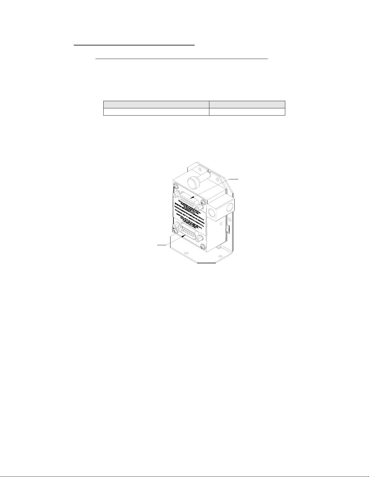
SERI AL DATA
RECEPTACLE DA-15S
PARALLEL DATA AND POWER
CONNECTOR DA-15P
Page 10 of 57
Section 2.0 Operation
2.1 General
The SSD-120(XX)N( )-RS5 series of altitude digitizers are designed to be mounted within a
pressurized or non-pressurized, but temperature controlled area within aircraft operating up
to 42,000 feet MSL. Usually remotely located, the digitizer is fully automatic in operation.
The parallel data output is controlled by the transponder while the serial altitude data is
transmitted asynchronously. (Half duplex, talk only. Full duplex in calibration and
configuration modes only.)
2.2 Operating Instructions
Parallel Data:
Place the transponder in mode “C”, altitude-reporting mode, and apply power to the
transponder and to the digitizer. In some installations the digitizer will automatically be
supplied power when the transponder is energized; in others, power to the digitizer may be
through a separate circuit breaker. If power to the digitizer is provided directly from the
aircraft’s avionics buss, follow the power-up procedures recommended by the transponder
manufacturer. All parallel outputs will be pulled low for a self-test (3 seconds) at power up,
then assume the value for the present input pressure. Note, a short the warm-up time may
affect the actual data enable time. At 0ºC a 30 second period is required before the data
will enable. In some installations, the transponder controls the digitizer by enabling and
disabling its output. In other installations, the digitizer’s output is not controlled by the
transponder and is continuously enabled, (Digitizer pin 6 is grounded.)
Serial Data
The serial communication is fully automatic and transmission begins after the self-test is
complete. Strobing (pin 6) the parallel ICAO altitude data output of the digitizer will not
affect the serial data transmission.
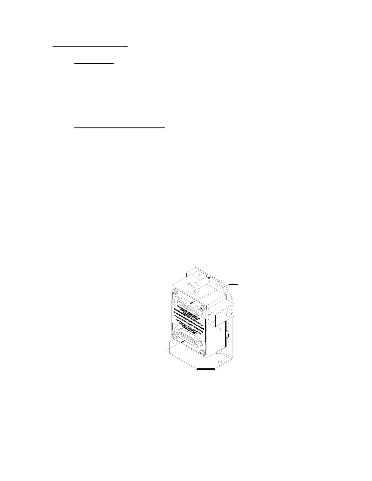
SERI AL DATA
RECEPTACLE DA-15S
PARALLEL DATA AND POWER
CONNECTOR DA-15P
Page 11 of 57

Page 12 of 57
Section 3.0 Installation
3.1 Mechanical Installation
The SSD120-(XX)N( )-RS5 series of digitizer may be mounted in any attitude within
the internal structure of the aircraft. DO NOT mount the digitizer in the direct air stream of
either hot or cold air ducts. The mounting position should allow for a short static pressure
line from the digitizer to the altimeter, access to the digitizer’s adjustments, and ample
room for a service loop for the interconnecting cabling to the transponder. The SSD120-
(XX)N-RS5 is provided with two static port inlets, either or both may be used to connect the
digitizer to the aircraft static system. If only one static port inlet is used, install the 1/8-
27NPT plug included with the connector kit into the unused static port. Apply pipe sealant
(not included) or equal to the plug. Exercise care to prevent excess sealant from plugging
the inlet to the pressure sensor.
On SSD120-(XX)NE-RS5 devices operating below -20ºC, use metal fittings on all
static line connections. The coefficient of thermal expansion for nylon is roughly three times
that of aluminum. Nylon and plastic fittings will leak at low temperatures due to thermal
contraction. Use an appropriate anti-seize compound when mating metal fittings to the
encoder.
To prevent the accumulation of condensation in the digitizer, locate this device away
from the lowest section of the static system, and ensure a proper condensation trap and
system drain is installed and functional.
Use #4-40 or #6-32 machine screws, sheet metal screws, or pop rivets to attach the
digitizer or the mounting tray to the airframe. Secure mating connectors to the digitizer
housing using the #4-40 screws provided. Refer to the outline drawing for mechanical
dimensions.
Adapter plates are available to convert older Trans-Cal and competing digitizer
installations for use with the SSD120-(XX)N(X)-(X) series of altitude digitizers. See
ordering information in §8.0.
3.2 Electrical Installation
Please note, proper solder or crimp techniques should be observed when attaching wires to
the mating connectors. Failure to do so could result in damage, intermittent operation or non-
operation of the digitizer. Shielded cable is recommended for both serial and parallel data
wiring harnesses. Wire and harnesses should be installed in such a way that the weight of
the cable bundle does not exert a force on the connector pins. The digitizer is designed to
operate with either a +14 or 28 Vdc power source. These voltages may be A+ switched
power provided by the transponder or may be provided by the avionics buss. Protect the
Trans-Cal encoder with a ½ amp fuse or circuit breaker.
Parallel Data Connection
The outline drawing provides electrical connector pin/function information. Use this
data when connecting the digitizer to the transponder. In some installations where older
transponders are used, the transponder may not provide an “altitude disable” function. In
this case, an instrument panel mounted switch for this function may be required.
Serial Data Connection (Table IX lists the pin assignments for the serial port receptacle.)
Connect the TxD1 through TxD53 (transmit data) from the 15-pin D-Subminiature
connector to the RxD (receive data) port on the GPS or other navigation devices. All
3The selected serial data protocol is transmitted simultaneously on all outputs, unless assigned separately in two groups via Serial Port
Software Configuration see §4.6.
grounds on the 15 pin D-subminiature connector are internally connected to ground and
may be used to ground protocol pins, as well as provide data ground to the receiving GPS
or other device. Pin 3 (RxD) of the 15-pin serial data connector is used for calibration only.
See Table IX for connector pin assignments and §4.6 through §4.10 for software assigned
protocols. Shielded cable is recommended for both serial and parallel data wiring
harnesses.
3.3 Serial Altitude Data Port Test Equipment
The output of the serial port may, or may not be directly displayed by the GPS or
other device receiving the serial data. There are several ways to test the output of the
serial port:
a) Use a TCI Model ATS-400 Test Set to display the serial altitude data.
b) Connect to an open serial port on a personal computer using serial data
capture software such as PROCOMM™, VERSATERM™, SOFTWARE WEDGE™,
TERMINAL (Windows® 3.x) or HYPERTERMINAL (Windows® 95, 98, 2000 or XP.)
c) Use a dedicated serial data test box such as the BLACK BOX™ RS232
Monitor.
d) Test for serial output using an oscilloscope to view the 9 Vdc square wave
group transmitted about twice a second.
3.4 Parallel ICAO Altitude Data Port Test Equipment
The output of the parallel ICAO altitude data may be monitored by any number of
transponder ramp test sets, which allow display of the ICAO altitude digitizer/encoder code.
The IFR Model ATC-600A Portable Transponder Test Set is one example. Alternatively,
the Trans-Cal Industries’ ATS-400 or EET-200 may be used to display the parallel data.
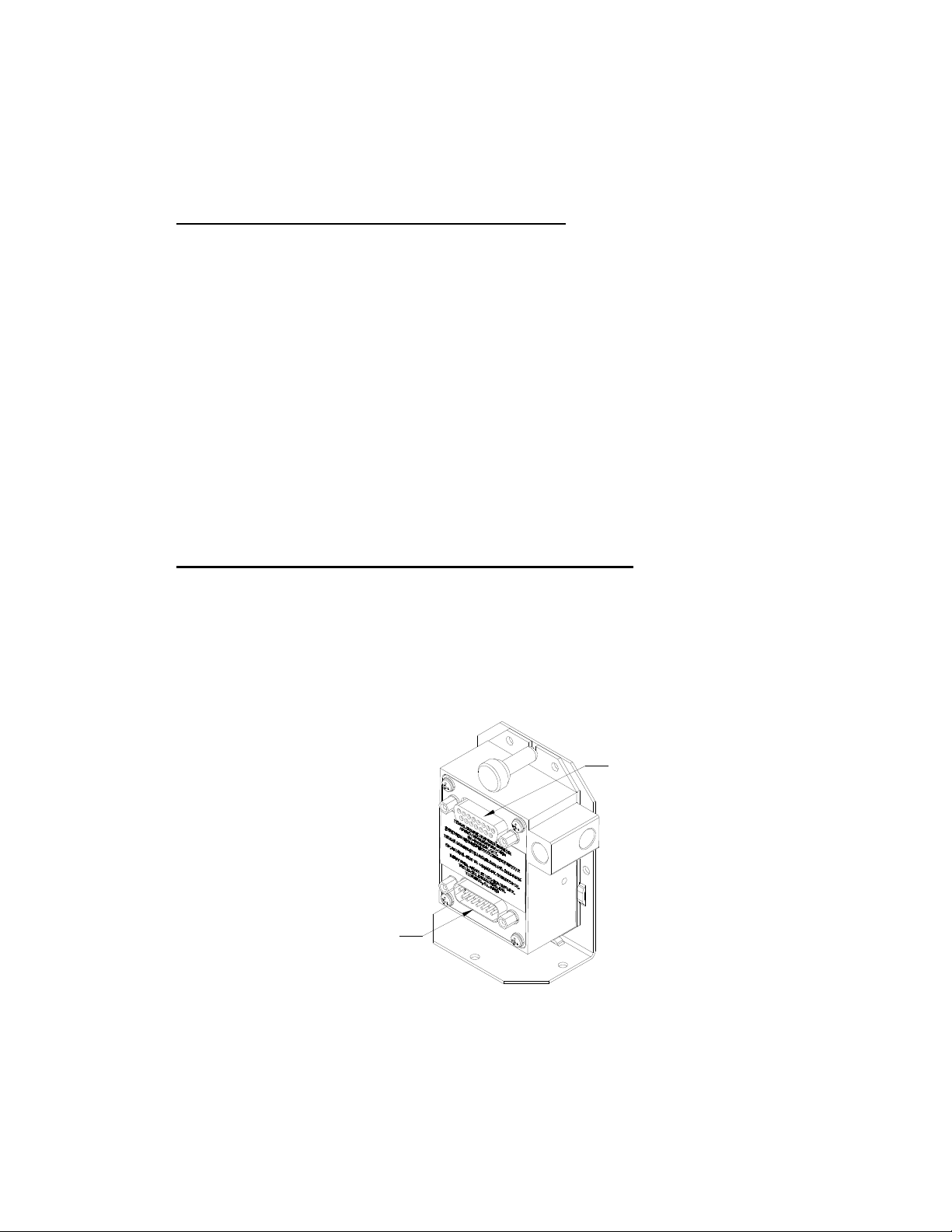
SERI AL DATA
RECEPTACLE DA-15S
PARALLEL DATA AND POWER
CONNECTOR DA-15P
Page 13 of 57

Page 14 of 57
Section 4.0 Calibration and Configuration
4.1 Calibration Overview
Reference: FAR 91.217; FAA Advisory Circular 43-6B
FAR 91.411; FAR 43-Appendix E and F
FAA TSO-C88a; EASA ETSO-C88a SAE AS8003
This procedure will allow adjustment to the calibration curve of the SSD120-(XX)N-RS5 or
SSD120-(XX)NE-RS5 as an aide in matching the digitizer output to a primary flight
altimeter or NIST traceable pressure standard. The maximum allowed error between the
primary flight altimeter and the altitude digitizer is ±125 feet as required by TSO-C88a and
ETSO-C88a. All Trans-Cal digitizers are calibrated to within ±50 feet of a NIST traceable
pressure standard; however, the error allowed on altimeters at higher altitudes could lead
to a combined error in excess of ±125 feet. When the altitude digitizer is installed in an
aircraft for use as the transponder’s source of mode “C” information the digitizer must be
recalibrated for correspondence to the aircraft’s primary flight altimeter, as required by FAR
91.217 and 91.411. Model SSD120-(XX)N-RS5 and SSD120-(XX)NE-RS5 are designed
to be field calibrated to meet this requirement, as per the procedure described in either
§4.4 or §4.8. The correspondence required for altitude digitizers is fully addressed in SAE
Aerospace Standard AS8003 §3.11. The correspondence described by the SAE standard
requires the digitizer to report altitude within ±125 feet of the primary flight altimeter’s
reading when the pressure datum is set to 29.92 In. Hg., (1013 MB) absolute. The SAE
standard also requires a transition accuracy of ±75 feet of the nominal transition point for
that altitude. A transition is defined as the point at which the digitizer changes from one
altitude to the next, either increasing or decreasing altitude. The nominal transition point of
the ICAO code occurs 50 feet prior to the altitude in question. See Figure 1.
There are two different methods used to change the calibration of this device. The
technician need only perform the method that is best suited for the application in question.
There is no need to perform both methods.The digitizer may be adjusted using two
potentiometers, which affect the span and reference of the pressure transducer. This
device may also be adjusted utilizing an externally addressable EEPROM, which is
configured to accept an alternate error curve entered to the digitizer via an IBM compatible
PC.
The Span Adjust calibration (§4.4) is normally used in applications where only a slight
modification is required to bring the altitude digitizer curve up or down.
The Dynamic Calibration procedure (§4.8) is an alternate method used to match the
altitude digitizer to the primary flight altimeter or NIST standard. It assumes the digitizer
and altimeter are connected as shown in the Dynamic Calibration Block Diagram and
the technician may adjust the input pressure to run the digitizer and primary flight altimeter
to the same altitude and then enter this altitude into an IBM compatible computer, which
will transmit the correction to the digitizer’s EEPROM. This calibration procedure differs
from the Span Adjust procedure in that the adjustments are made at every 1000-foot
interval and the Digitizer is adjusted at the 0 foot mark NOT the ICAO data nominal
transition point.

Page 15 of 57
4.2 Required Equipment Span Adjust
(See span adjust block diagram.)
1. Primary Flight Altimeter.
2. +12 or 28VDC power supply.
3. A pitot-static test set, capable of exercising the altimeter and digitizer over a range of –
1000 feet to the maximum altitude of the digitizer.
4. A ramp checker or test set capable of interrogating the transponder. Optional: ATS-400 or
equal device which will allow the display of the 100 foot resolution parallel altitude data.
4.3 Required Equipment Dynamic Calibration
(See dynamic calibration block diagram.)
1. Primary flight altimeter or NIST traceable pressure standard.
2. +12 to 28VDC power supply.
3. IBM compatible computer with an available serial port, OR Trans-Cal Industries ECP-100
Calibration/Programmer.
4. Software requirement: Windows 98®, Windows 2000® or Windows XP® using Hyper
Terminal Ver. 5.0 by Hilgraeve. (Available as a free download at http://www.hilgraeve.com) Or
equal serial data capture software. See §3.3a. (Windows Vista® is not currently supported by
Hyper Terminal.)
5. A pitot-static test set, capable of exercising the altimeter and digitizer over a range of -1000
feet to the maximum altitude of the digitizer.
6. Optional: ATS-400 or equal device which will allow the display of the 100 foot resolution
parallel altitude data.
4.4 Span Adjust Procedure
1. Connect the pitot-static test equipment to the aircraft’s static line, and connect the transponder
test set per the manufacturer’s recommendations. The digitizer’s two altitude adjustment
potentiometers are identified as L and H, representing low and high altitude. The low
adjustment is closest to the edge of the housing, and the high adjustment is closer to the
center of the housing.
(Note: Changing either potentiometer will affect the other. An adjustment made to correct the low
transition point, will move the high transition point, and require an adjustment of the high
potentiometer.)
2. Apply power to the altitude digitizer/transponder.
3. Set the primary flight altimeter barometric pressure adjustment to 29.92 In. Hg. (1013 MB).
4. Interrogate the transponder with the ramp tester, while observing the digitizer ICAO altitude
code, decrease pressure to the point where the altitude code just makes a transition to the
maximum altitude encoded. Verify that the digitizer is within ±125 feet of the primary flight
altimeter’s reading. If not, adjust the high potentiometer until the digitizer transition point is

Page 16 of 57
within ±30 feet of the nominal transition point. (i.e. while ascending, the digitizer should
transition from 29,900 feet to 30,000 feet at 29,950 feet nominally.)
5. Increase pressure until the digitizer’s output just makes the transition from 100 feet to 0 feet.
Verify that the altitude digitizer reports within ±125 feet of the primary flight altimeter. If not,
adjust the low potentiometer until the transition point is within ±30 feet of the nominal transition
point. (i.e. while descending, the digitizer should transition from +100 to 0 feet at +50 feet
nominally.)
6. Repeat steps (4) and (5) until the ±125 foot tolerance is achieved for both the maximum
calibration altitude and the minimum calibration altitude.
7. Exercise the aircraft’s static system over the operating range of the altitude digitizer and, with
increasing and decreasing pressure, verify at a minimum of ten test points that the altitude
digitizer and primary flight altimeter correspond within the ±125 foot tolerance. Lightly tap the
altimeter before each reading to eliminate friction. If correspondence is not achieved at any test
point, the altimeter may require calibration.
8. Verify that the digitizer’s output is disabled when the transponder is not in mode “C”, or when
the “Altitude Disable” switch is in the off position.
CAUTION: Always refer to the altimeter and VSI manufacturer’s data for maximum rate of climb or
descent, and any special test conditions which must be complied with.
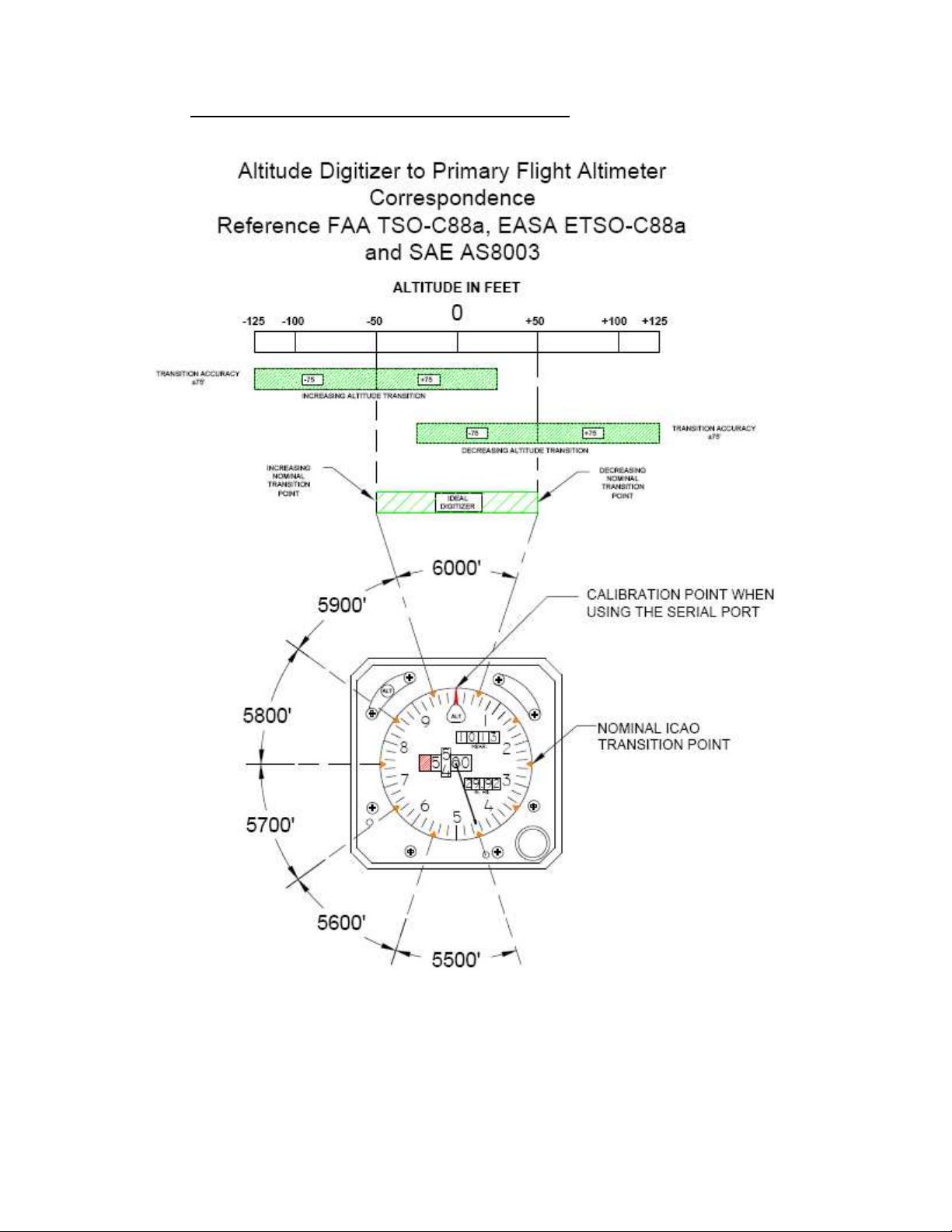
Figure 1 Altitude Digitizer Correspondence
Page 17 of 57

Page 18 of 57
4.5 Dynamic Calibration Adjustment Procedure using the ECP-100
Reference: FAR 91.217; FAA Advisory Circular 43-6B
FAR 91.423; FAR 43-Appendix E and F
FAA TSO-C88a, EASA ETSO-C88a, SAE AS8003
This procedure will allow adjustment to the calibration curve of the SSD120-(XX)N-RS5 or
SSD120-(XX)NE-RS5 using the ECP-100 as an aide in matching the digitizer output to a primary
flight altimeter or NIST traceable pressure standard. This procedure differs significantly from the
Span Adjust Procedure described in §4.4. The Dynamic Calibration Procedure makes
adjustments to the altitude data stored in the digitizer’s EEPROM. The technician may make
adjustments to the digitizer error curve in 1000 foot increments, over the entire operating range
with the single exception of the –1000 foot mark. The technician will make the adjustments at the 0
or whole altitude mark, NOT at the parallel data’s nominal transition point. See Figure 1. The
digitizer will automatically adjust the ICAO parallel altitude data to transition 50 feet prior to the 0
mark. (i.e. the digitizer’s ICAO parallel altitude code will transition from 900 to 1000 feet while the
serial altitude data is transmitting 950 feet.)
1. Connect the digitizer, ECP-100, NIST standard or flight altimeter as shown in the Figure 2
and apply power.
2. Slide the ECP-100 CAL. PROGRAM selector to the leftmost PROGRAM position.
3. Apply power to the altitude digitizer and slide the ECP-100 power switch to the on position.
4. Set the altimeter barometric input to 29.92In.Hg. (1013MB). Adjust the static system
pressure and stabilize at the first altitude to be calibrated. The first possible correction for
Trans-Cal digitizers is at 0 feet. All adjustments to the digitizer calibration curve occur at
1000-foot intervals. Use the ALTITUDE UP and ALTITUDE DOWN buttons to adjust the
ECP-100 to the current pressure altitude prior to pushing the INITIATE PROGRAM
pushbutton.
5. Press the INITIATE PROGRAM pushbutton once. THE ECP-100 will enter a digital
correction into the digitizer’s EEPROM at the current pressure altitude.
6. Adjust the input pressure to the next 1000-foot increment and adjust the ECP-100 to the
next 1000-foot increment and repeat step 5. Continue repeating throughout the operating
range of the altitude digitizer.
7. Exercise the aircraft’s static system over the operating range of the altitude digitizer and,
with increasing and decreasing pressure, verify at a minimum of ten test points that the
altitude digitizer and primary flight altimeter correspond within the ±125 foot tolerance.
Lightly tap the altimeter before each reading to eliminate friction. If correspondence is not
achieved at any test point, the altimeter may require calibration.
8. Verify that the digitizer’s output is disabled when the transponder is not in mode “C”, or
when the “Altitude Disable” switch is in the off position.
NOTE: If an error is entered into the digitizer, adjust the pressure to the correct altitude and re-enter the correction. To
clear ALL the corrections to the digitizer error curve press the ALTITUDE UP PROGRAM pushbutton once. Then
press and hold the ALTITUDE DOWN button for two seconds.
If the digitizer and flight altimeter are within the ±125-foot requirement then no correction is required.
DO NOT adjust the digitizer high and low potentiometers during or after this procedure.

Figure 2 Dynamic Calibration Set-Up Using the ECP-100
Page 19 of 57

4.6 Hyper Terminal Set-Up on the IBM Compatible PC
Boot up the computer and start the serial data capture software such as the Hyper Terminal
program. Hyper Terminal may be located in the Programs section or in the Accessories section
under Communications, and Hyper Terminal will be used for the balance of the examples used in
this manual.
Under the New Connection window:
Choose an icon then select an identifying title such as “Test.”
SelectOK after you have made your choices.
Under the Connect to window:
-Choose Connect Using Com 1 or whatever Com port you have chosen to use.
After your selection click on OK.
Under the Com ? Properties window:
Select the Port Settings tab and set the following:
Bits per second: 9600
Databits: 8
Parity: None
StopBits: 1
FlowControl: None
SelectOK
In the Hyper Terminal window select File then click on Properties.
Under the Com ? Properties window click on the Settings tab.
Set the following:
Function, arrow, ctrl keys to act as Terminal Keys.
Emulation to Auto Detect
UnderASCII Setup
Setthefollowing:
Echo off.
Wrap lines that exceed terminal width.
SelectOK.
The software is now configured for operation.
Note: Past versions (Ver. 5 thru 6) of HyperTerminal have a known issue when communicating with serial
protocols of 7 data bits, 1 stop bit, odd parity. This Windows® program will not correctly auto detect the protocol,
but will display the data when manually configured.
Page 20 of 57
This manual suits for next models
1
Table of contents
Other Trans-Cal Media Converter manuals


