Trans-Cal SSD120 M Series Use and care manual
Trans-Cal Industries, Inc.
Installation and Calibration Manual
(Patent Pending)
Model SSD120-(XX)M
Modular Altitude Encoder / Digitizer Series
TSO-C88a Approved
Trans-Cal Industries, Inc.
Van Nuys Airport
16141 Cohasset Street
Van Nuys, CA 91406-2908
(818) 787-1221 FAX (818) 787-8916
http://www.trans-cal.com
21 June 2005 Document 881600 Revision C
2
This document may not be reproduced, transmitted, or copied in any form without prior
written consent of Trans-Cal Industries. The data contained herein is subject to change
without notice.
Please Note:
It is the responsibility of the installer of this equipment, and those performing
this procedure, within a specific type or class of aircraft, to determine that the
aircraft operating conditions are within TSO standards.
Trans-Cal Industries, Inc. 16141 Cohasset
Street Van Nuys, CA 91406
818/787-1221 (800)423-2913 818/787-
8916FAX www.Trans-Cal.com
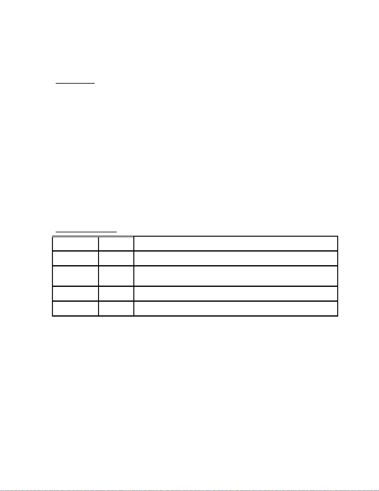
History of Revision
Revision Date Description
07/00 Production release.
A 08/00 Removed protocol jumper info., added prgm. pin Y data. Added baro set pin and
external wire data.
B 09/00 Changed outline drawing to revision C.
C 06/05 Updated document layout, added wiring diagram 101802.dwg

3
Table of Contents
Section 1.0 Introduction...................................................................................................... 4
1.1 Equipment Description ............................................................................................. 4
1.2 General Specifications.............................................................................................. 4
1.2.1 Operating Altitude ............................................................................................. 5
1.2.2 Accuracy............................................................................................................ 5
1.2.3 Serial Port Data Resolution................................................................................ 5
1.2.4 Mechanical Characteristics................................................................................ 5
1.2.5 Environmental.................................................................................................... 5
1.2.6 Over Range ........................................................................................................ 5
1.3 Parallel Altitude Data Port Specifications ................................................................ 6
1.4 Serial Altitude Data Port Specifications................................................................... 6
1.5 Serial Communication Format.................................................................................. 7
1.6 Serial Communication Protocol................................................................................ 7
Section 2.0 Operation.......................................................................................................... 9
2.1 General...................................................................................................................... 9
2.2 Operating Instructions............................................................................................... 9
2.2.1 Parallel Altitude Data......................................................................................... 9
2.2.2 Serial Altitude Data............................................................................................ 9
Section 3.0 Installation and Calibration............................................................................ 10
3.1 Mechanical Installation........................................................................................... 10
3.2 Electrical Installation.............................................................................................. 10
3.2.1 Parallel Altitude Data Connection................................................................... 10
3.2.2 Serial Altitude Data Connection...................................................................... 10
3.3 Serial Data Port Test Equipment............................................................................. 11
3.4 Parallel Data Port Test Equipment.......................................................................... 11
Section 4.0 Configuration and Calibration ....................................................................... 12
4.1 Configuration and Calibration Procedure............................................................... 12
4.2 Required Equipment for Calibration:...................................................................... 13
4.3 Hyper Terminal Software Set-Up on the IBM Compatible PC.............................. 14
4.4 SSD120-(XX)M Serial Port Software Configuration............................................. 15
4.5 SSD120-(XX)M Calibration Adjustment Procedure.............................................. 17
4.6 Configuration and Calibration Command List ....................................................... 20
4.7 Error Correction Table............................................................................................ 21
Encoder/Digitizer / Transponder Interconnections....................................................... 22
26 Pin Connector Assignments..................................................................................... 26
GPS Connection Data................................................................................................... 27
26 Pin Connector Cutout 881667.................................................................................. 30
Wiring Harness Diagram 881668 ................................................................................. 31
Calibration Block Diagram 881669.............................................................................. 32
Outline Drawing Modular Altitude Digitizer SSD120-(XX)M.................................... 33
Wiring Diagram 101802............................................................................................... 34
WARRANTY REGISTRATION ..................................................................................... 36

4
Section 1.0 Introduction
This manual provides detailed installation, calibration and operating instructions for
Trans-Cal Industries’ Modular Altitude Encoder/Digitizer Model SSD120-(XX)M.
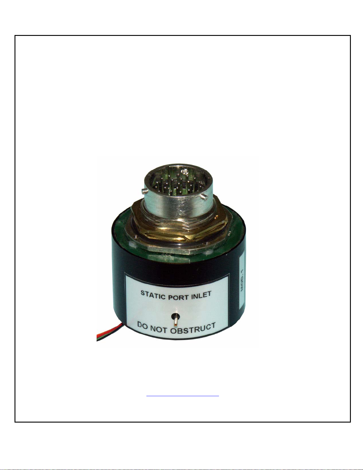
1.1 Equipment Description
Approved under F.A.A. TSO-C88a, the Model SSD120-(XX)M is an all
solid state electronic device which, when installed within a flight altimeter
and connected to the aircraft’s electrical system, converts pressure altitude
information into parallel and serial digital data.
The parallel digital data is set forth in the (ICAO) International Standard
for SSR Pressure Altitude Transmission. In accordance with U.S. National
Standards for Common System Component Characteristics for the I.F.F.
Mark X (SIF)/Air Traffic Control Radar Beacon System SIF/ATCRBS.
The serial altitude data is provided on (2) two asynchronous RS232 output
ports. The serial data protocol is individually selectable for each port (refer
to Table V, and §4.4)
This unit is also designed to be programmed to match the flight altimeter
error curve utilizing an IBM compatible PC with an available serial port.
1.2 General Specifications
Operating voltage: Model SSD120-(XX)M +9 to 30 VDC.
Operating current: Model SSD120-(XX)M 0.1 Amperes Max.
Operating temperature/warm-up time:
Model SSD120-(XX)M: -30° to +70°C No warm-up time required.
Storage temperature all models (non-operating): -55° to +85°C.
Weight: 3.82 oz. (108.2 grams)

5
1.2.1 Operating Altitude
Model SSD120-50M -1000 to +50,000 feet.
Model SSD120-62M -1000 to +62,000 feet.
Model SSD120-65M -1000 to +65,000 feet.
Model SSD120-80M -1000 to +80,000 feet.
1.2.2 Accuracy
Accuracy throughout operating temperature range -30° to +70°C.
-1000 to +42,000 feet ±50 feet.
+42,100 to maximum altitude ±75 feet.
1.2.3 Serial Port Data Resolution
The resolution of the serial port altitude data is selectable in 100
foot or 10 foot increments. The default resolution of the altitude
digitizer serial data is 100 feet. To enable 10 foot resolution
configure the SSD120-(XX)M via software see §4.4.
1.2.4 Mechanical Characteristics
Model Number Dimensions Weight
All models. See outline drawing. 3.8 oz. (107.648g)
1.2.5 Environmental
All Model SSD120-(XX)M series of altitude encoder/digitizer
have been designed and tested to meet the requirements of TSO-
C88a, in accordance with RTCA Document DO160b, dated July
1984 (specifics provided upon request).
1.2.6 Over Range
The SSD120-(XX)M series of altitude encoder/digitizer will not be
damaged when operated beyond its specified maximum altitude
and may be exposed to a pressure equivalent to 100,000 feet, or
over pressured to 18 psi max.

6
1.3 Parallel Altitude Data Port Specifications
Code Format:
In accordance with the U.S. National Standard for Common
System Component Characteristics for the I.F.F. Mark X (SIF) Air
Traffic Control Radar Beacon System, SIF/ATCRBS.
Driver Description:
The parallel altitude data output is provided by the “uncommitted”
collectors of a transistor array and must be “pulled-up” through a
resistive load by the transponder.
Pull-Up Voltage: +3 to 50VDC.
Maximum Sink Current: 50 milliamperes.
Maximum Cable Length: 4000 feet.(1219 meters)
Input Signal Requirement: Pin A (strobe or signal common) must be
either rounded or connected to the
transponder.
1.4 Serial Altitude Data Port Specifications
Electrical Format: conforming to the TIA/EIA RS232E standard.
Logic levels: ‘0’, +9 volts. Logic ‘1’, -9 volts.
Driver output maximum voltage: ±25 VDC.
Driver load impedance: 3KStyp.
One receiver allowed per serial port.
Maximum cable length: 50 feet. (15 Meters)
Code format: ASCII.
Communication system: simplex (talk only).
Transmission Method: asynchronous.
Transmission rate: selectable, 1200 bps to 9600 bps.
Update rate: 10/sec.

7
1.5 Serial Communication Format
Model SSD120-(XX)M and carries out serial communication
asynchronously with the “Start/Stop” system. This system puts a start bit
at the head of a character, and then in turn adds data bits, a parity bit, and a
stop bit. The specifics of the protocol are determined by user selection, see
§4.4, and Table V.
1.6 Serial Communication Protocol
The serial data protocol is user selectable via software see §4.4. If the
installation calls for two separate protocols to be transmitted on the serial
data ports the second protocol may be software assigned. The following
list of protocols is referred to in §4.4.
Protocol 1 which is compatible with UPS Aviation Technologies’ Apollo
(IIMorrow) Navigation devices. At a baud rate of 1200 bps the encoder
sends a seventeen byte message beginning with # AL, then a space
followed by five altitude bytes ; the letter "T" and the number "25"; two
checksum bytes and a carriage return.
An example of a serial message for UPS AT Apollo devices:
Message: Definition:
#AL +00800T+25D8r Altitude 800 feet
Protocol 2 is compatible with some navigation devices manufactured by
Trimble and Garmin. At a baud rate of 9600 bps the encoder sends a ten
byte message. The message begins with ALT followed by a space and five
altitude bytes; concluding with a carriage return. Examples of serial
messages for Trimble or Garmin devices:
Message: Definition:
ALT 10500 r Altitude 10,500 feet

8
1.6 Serial Communication Protocol (continued)
Protocol 3 is compatible with some navigation devices manufactured by
Northstar and Garmin. At a baud rate of 2400 bps the encoder sends a 10
byte message. The message begins with ALT followed by a space and five
altitude bytes; concluding with a carriage return. Examples of serial
messages for these devices:
Message: Definition:
ALT 02500 r Altitude 2500 feet
Protocol 4 is compatible with some navigation devices manufactured by
Magellan. At a baud rate of 1200 bps the encoder sends a seventeen byte
message beginning with $MGL, followed by a +/- sign and five altitude
digits, then T+25, a checksum and concludes with a carriage return.
Examples of serial messages for Magellan devices:
Message Definition:
$MGL+02500T+25D6 r Altitude 2500 feet.
Protocol 5 is compatible with some navigation devices manufactured by
ARNAV Systems. At a baud rate of 9600 bps the encoder sends a twenty
two byte message beginning with $PASHS, followed by ALT; a +/- sign
and five altitude digits, then a* as delimiter, a checksum and concludes
with a carriage return/line feed. Examples of serial messages forARNAV
devices:
Message Definition:
$PASHS,ALT,+00033*1Brs Altitude 33 meters.

9
Section 2.0 Operation
2.1 General
The SSD120-(XX)M series of altitude encoder/digitizer’s are designed to
be mounted within the body of a flight altimeter operated up to 80,000
MSL. The encoder/digitizer is fully automatic in operation. The parallel
data output is controlled by the transponder while the serial data is
transmitted asynchronously.
2.2 Operating Instructions
2.2.1 Parallel Altitude Data
Place the transponder in Mode ‘C’, altitude reporting mode, and
apply power to the transponder and the encoder/digitizer. In some
installations, the encoder/digitizer will be automatically supplied
power when the transponder is energized; in others, power to the
encoder/digitizer is provided directly from the avionics buss,
follow the power-up procedures recommended by the transponder
manufacturer.
In some installations the transponder controls the encoder/digitizer
by enabling and disabling its outputs. In other installations, the
encoder/digitizer’s output is not controlled by the transponder and
is continuously enabled, (encoder/digitizer pin A is grounded.)
2.2.2 Serial Altitude Data
The serial data communication is fully automatic and transmission
begins immediately upon power up to the encoder/digitizer. The
serial communication is not affected by the strobe function on the
parallel data.

10
Section 3.0 Installation and Calibration
3.1 Mechanical Installation
The SSD120-(XX)M series altitude encoder/digitizer may be mounted in
any attitude within the body of the altimeter, but should be mounted to
insure no interference with the altimeter mechanism, and no obstruction of
the SSD120-(XX)M static pressure inlet. The mounting position should
insure that the 26 pin mating connector does not interfere with the
altimeter static port connection or other electrical or mechanical
connections required for the altimeter’s operation.
Manufacture an opening in the altimeter case per the outline drawing for
the Connector Panel Cutout 881667. Be sure to provide a flat surface to
which the connector O-Ring can seal. Secure the encoder/digitizer to the
altimeter case using the 1c-18 nut provided. Refer to the outline drawing
for mechanical dimensions and the sample installation diagram.
3.2 Electrical Installation
The encoder/digitizer is designed to operate with a +9 to +28VDC power
source. This voltage can be A+ switched power provided by the
transponder or can be provided by the avionics buss, protected with the
appropriate fuse or circuit breaker.
3.2.1 Parallel Altitude Data Connection
The outline drawing provides electrical connector pin/function
data. Use this information when connecting the encoder/digitizer to
the transponder. In some installations where older transponders are
in use, the transponder may not provide an “altitude disable”
function. In this case a panel mounted switch may be required.
3.2.2 Serial Altitude Data Connection
Connect the TxD (transmit data) pin X (TxD1) or pin U (TxD2)
from the connector to the receive data RxD port on the GPS or
other navigation device. See connection Table V as well as the
GPS Connection Data. Be sure to connect a ground from the
encoder/digitizer to the receiving GPS unit to ensure good data
transmission. Shielded cable is recommended for both serial and
parallel data wiring assemblies.

11
3.3 Serial Data Port Test Equipment
The output of the serial port may, or may not be displayed by the GPS or
other device receiving serial data. There are several ways to test the output
of the serial port:
A. Connect to an open serial port on a personal computer
using serial data capture software such as
PROCOMM™ , VERSATERM™, SOFTWARE
WEDGE™, TERMINAL (Windows® 3.x) or
HYPERTERMINAL (Windows® 95 & 98).
B. Use a dedicated serial data test box such as BLACK
BOX™ RS232 Monitor.
C. Test for serial output using an oscilloscope to view the 9
VDC square wave, transmitted once a second.
3.4 Parallel Data Port Test Equipment
The output of the parallel port may be displayed on any number of ramp
test sets capable of interrogating the transponder and displaying the
altitude code from the encoder/digitizer. Or the Trans-Cal ATS-200 test
set may be used to display the encoder/digitizer output.

12
Section 4.0 Configuration and Calibration
4.1 Configuration and Calibration Procedure
Overview:
This procedure will allow configuration of the serial ports on the
SSD120-(XX)M to transmit the desired protocol, format and
altitude data resolution.
This procedure will also allow adjustment to the calibration curve
of the SSD120-(XX)M to match the encoder/digitizer output to a
flight altimeter or NIST traceable pressure standard. The maximum
allowed error between the primary flight altimeter and the altitude
digitizer is ±125 feet as required by TSO-C88a. All SSD120-
(XX)M digitizers are calibrated to NIST traceable pressure
standards; however, the error allowed on altimeters at altitudes
above 30,000 feet, can lead to a combined error in excess of ±125
feet between the two instruments. The SSD120-(XX)M utilizes an
externally addressable EEPROM which is configured to accept an
alternate error table communicated to the encoder/digitizer via an
IBM compatible PC.
This procedure assumes the SSD120-(XX)M is installed within an
altimeter referenced to 29.92 In.Hg.(1013.25MB) The technician
must be capable of adjusting the input pressure to run the
encoder/digitizer and altimeter to a stable pressure altitude, and
then enter this altitude into an IBM compatible computer which
will transmit the correction to the digitizer’s error table.

13
4.2 Required Equipment for Calibration:
(See Calibration Block Diagram 881669.)
1. SSD120-(XX)M installed within a flight altimeter.
2. +12 to 28VDC power supply.
3. IBM compatible computer with an available serial port.
Software requirement: Windows 98® using Hyper Terminal Ver. 5.0
by Hilgraeve.
(Available as a free download at http://www.hilgraeve.com)(Software
Note: The
Hyper Terminal program which is shipped with Windows 98® will
not function
correctly. You must download version 5.0 or better to use this
calibration program.)
4. Digitizer/PC interface cable. (See wiring harness diagram or order
881668 from
Trans-Cal Industries.)
5. Vacuum/pressure source and control capable of exercising the
digitizer/altimeter, pressure standard over the digitizer’s operating
range. (Optional: ATS-200 or equal device which will allow the
display of the parallel 100 foot altitude data.)

14
4.3 Hyper Terminal Software Set-Up on the IBM Compatible PC
Boot up the computer and start the Hyper Terminal program. Hyper
Terminal may be located in the Programs Section or in the Accessories
Section under Communications .
Under the New Connection window. (Identifies the new connection.) -
Choose an icon then select an identifying title such as “Test.” Select OK
after you have made your choices.
Under the Connect to window (Selects the Com port to use.) -Choose
Connect Using Com 1 or whatever Com port you have chosen to use.
After your selection click on OK.
Under the Com ? Properties, (Sets communication properties.) Under the
Port Settings tab, set the following:
Bits per second: 9600
Data bits: 8
Parity: None
Stop Bits: 1
Flow Control: None
Select OK
In the Hyper Terminal window select File then click on Properties.
Under the Com ? Properties window click on the Settings tab. Set the
following:
Function, arrow, ctrl keys to act as Terminal Keys. Emulation to
Auto Detect
Under ASCII Setup Set the following:
Echo off.
Wrap lines that exceed terminal
width.
Select OK.
The software is now configured for operation.

15
4.4 SSD120-(XX)M Serial Port Software Configuration
This device incorporates two separate RS232E compatible outputs which may be
configured via software to transmit 2 different altitude data protocols
simultaneously.
1. Construct a wiring harness per the Wiring Harness Diagram 881668.
(This harness may be ordered directly from Trans-Cal Industries.
Please specify 9 pin or 25 pin connector.)
2. Connect the digitizer to an IBM compatible computer running
Hyperterminal as described in § 4.3 and as shown in the Calibration
Block Diagram 881669. Assign the serial port protocols as follows:

16
Apply power to the digitizer and after the data appears on the PC screen type the
following:
Type <enter> The Digitizer will return “?> current altitude”
Type ADJ <enter> Access the digitizer adjustment program.
The Digitizer will return A=
Type P <enter> To identify the current serial port settings.
(a) The first digit represents the serial altitude data resolution.
0 = Use D-Sub connector protocol hardware jumpers.
1 = 100 foot resolution on TxD1 and TxD2.
2 = 10 foot resolution on TxD1 and TxD2.
(b) The second digit represents the protocol selection for TxD1.
0 = Use D-Sub connector protocol hardware jumpers.
1 = UPS Aviation Technologies. 1200 bps.
2 = Trimble/Garmin. 9600bps.
3 = Northstar. 2400bps.
4 = Magellan. 1200bps.
5 = ARNAV. 9600bps.
(c) The third digit represents the protocol selection for TxD2.
0 = Use D-Sub connector protocol hardware jumpers.
1 = UPS Aviation Technologies. 1200 bps.
2 = Trimble/Garmin. 9600bps.
3 = Northstar. 2400bps.
4 = Magellan. 1200bps.
5 = ARNAV 9600bps.
Example: Type P212<enter> Defined as 10 foot resolution on TxD1 and TxD2.
UPS Aviation Technologies protocol transmitted
on TxD1. Trimble/Garmin protocol transmitted on
TxD2.
Type Q twice to exit the adjustment mode.
The Interface Adapter responds with a three-digit number as follows:
a b c
Serial Altitude Data Resolution TxD2 Protocol
TxD1 Protocol

17
4.5 SSD120-(XX)M Calibration Adjustment Procedure
This procedure is used to match the encoder/digitizer output to the flight
altimeter.
1. Construct a wiring harness per the Wiring Harness Diagram 881668.
(This harness may be ordered directly from Trans-Cal Industries. Part
Number 881668 please specify 9 pin or 25 pin PC connector.)
2. Connect the digitizer, computer and altimeter as shown in the
Calibration Block Diagram 881669, and energize. Set the altimeter
barometric reference to 29.92In.Hg. 1013.25MB.
3. Open the Hyper Terminal program as described in § 4.3.
4. The digitizer output should now be displayed on the PC screen with 10
footresolution.
(You may use the Hyper Terminal “Clear Screen” function to remove
any extra characters that may be cluttering the screen. Click on Edit then
click on Clear Screen.)
Note: Backspace does not function in Hyper Terminal. If a typing error
occurs, hit <enter> and begin again.
5. Change the input pressure to -1000 feet and begin to compare the
altitude digitizeroutput, as displayed on the computer, to the altimeter
reading at every 1000 foot mark. When the digitizer output begins to
differ from the altimeter by more than ±30 feet begin to change the
digitizer error curve. (§ 4.7 provides a table to give the technician a
record of changes required and implemented.)
(Note: no digitizer correction is possible at the -1000 foot mark.)
The following procedure allows changes to the error curve of the digitizer.
6. Connect the encoder/digitizer as shown in the Calibration Block
Diagram 881669.

18
CAUTION: Always refer to the altimeter manufacturer’s data for maximum rate of climb
or descent and any special test conditions which must be complied with.
Adjust the input pressure until the altimeter is exactly reading a 1000 footmark. Note the
difference between the digitizer and the altimeter. For example:
Adjust the input pressure until the altimeter is reading
10,000 feet.
In this case the altimeter reads 20,000 feet and the
encoder/digitizer
reads 20,080.
Type “ADJ<enter>” the computer should now display
“A=”
Type “S20 <enter>”
(S20 represents Save 20,000feet)
4.5 SSD120-(XX)M Calibration Adjustment Procedure (continued)
The digitizer will now output 20,000 based on the altimeter reading. And the PC will
display the altitude at which the digitizer will make this change. In the example above
the PC would display >20000.
Proceed to the next 1000 foot mark and repeat the procedure as in step 3above until the
entire operating range of the altimeter encoder/digitizer is complete.
(Note: If no correction is required at an altitude simply do not enter a
correction.)

19
After completing the above procedure you may look at the corrections entered into the
error table. Type “D<enter>” to dump the error data and read the current error curve on
the PC screen. The following error table should appear:
00= 000 01= 000 02= 000 03= 000 04= 000 05= 000
06= 000 07= 000 08= 000 09= 000 10=-080 11= 000
12= 000 13= 000 14= 000 15= 000 16= 000 17= 000
18= 000 19= 000 20= -080 21= 000 22= 000 23= 000
24= 000 25= 000 26= 000 27= 000 28= 000 29= 000
30= 000 31= 000 32= 000 33= 000 34= 000 35= 000
36= 000 37= 000 38= 000 39= 000 40= 000 41= 000
42= 000 43= 000 44= 000 45= 000 46= 000 47= 000
48= 000 49= 000 50= 000 51= 000 52= 000 53= 000
54= 000 55= 000 56= 000 57= 000 58= 000 59= 000
60= 000 61= 000 62= 000 63= 000 64= 000 65= 000
66= 000 67= 000 68= 000 69= 000 70= 000 71= 000
72= 000 73= 000 74= 000 75= 000 76= 000 77= 000
78= 000 79= 000 80= 000 81= 000 82= 000 83= 000
84= 000 85= 000 86= 000 87= 000 88= 000 89= 000
>current altitude
The first two digits represent altitude x1000 feet and the last three digits after the equal
sign represent the amount of error introduced at the altitude in feet.
Type Qtwice to exit the ADJ mode.

20
4.6 Configuration and Calibration Command List
Following is a list of commands which will operate in this Calibration mode.
Top Level Menu
ADJ <enter> Enter adjustment mode.
Q Quit command. Returns to normal operation.
Sub-Menu
CLR <enter> Clear command clears error table data.
D <enter> Dump to list all error table data.
P<enter> Port status command, displays the current
port status. See § 4.4.
Pabc<enter> Port command, sets the serial port
resolution and protocol. See §4.4.
Q Quit command. Returns to top level menu.
Saa<enter> Save to error table, 1000 foot altitude
(aa) mark at current input pressure.
NOTES:
1. Backspace does not function. If a typing error occurs hit <enter> and begin again.
2. A maximum error of ±499 feet may be introduced at any one altitude.
3. CLR clears all error data in the EEPROM.
Table of contents
Other Trans-Cal Media Converter manuals


