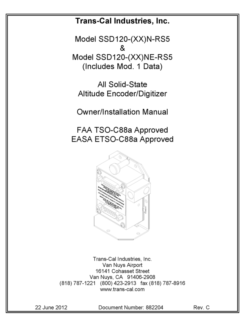
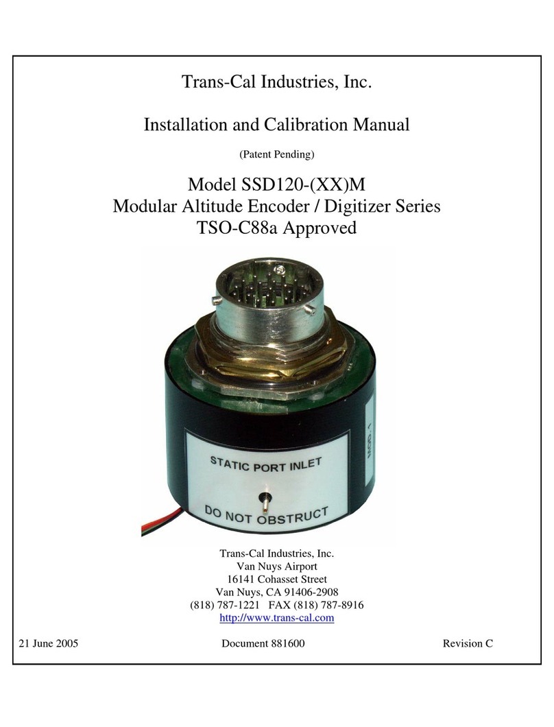
Trans-Cal SSD120-A-RS Series Quick start guide

Trans-Cal Industries, Inc.
Model SSD120-(XX)A-RS
&
Model SSD120-(XX)AE-RS
All Solid State
Altitude Encoder/Digitizer
Owner/Installation Manual
T.S.O. C88a Approved
Trans-Cal Industries, Inc.
Van Nuys Airport
16141 Cohasset Street
Van Nuys, CA 91406-2908
(818)787-1221 * (800)423-2913 * (818)787-8916FAX
www.trans-cal.com
30 August 2004 Document Number: 930006 Revision: C

-2-
This document may not be reproduced, transmitted, or copied in any form without the prior
written consent of Trans-Cal Industries, Inc. The data contained herein is subject to change
without notice.
Please Note:
It is the responsibility of the installer of this equipment, within a specific type or class of
aircraft, to determine that the aircraft operating conditions are within TSO standards.
Trans-Cal Industries, Inc.
16141 Cohasset Street
Van Nuys, CA 91406
818/787-1221
800/423-2913
FAX 818/787-8916
www.trans-cal.com
History of Revision
Revision
Date
Description
--
07/98
Production release.
A
10/99
Program Update Info.
B
03/31
Chngd. current pg. 1.
C
08/04
Updated manual.

-3-
Table of Contents
Section 1.0 Introduction.................................................................................................................4
1.1 Scope....................................................................................................................................4
1.2 Equipment Description ........................................................................................................4
1.3 General Specifications .........................................................................................................4
1.3.1 Operating Altitude: .......................................................................................................5
1.3.2 Accuracy: ......................................................................................................................5
1.3.3 Serial Port Altitude Data Resolution: ...........................................................................5
1.3.4 Mechanical Characteristics:..........................................................................................5
1.3.5 Environmental:..............................................................................................................5
1.3.6 Over Range: ..................................................................................................................5
1.4 Parallel Altitude Data Port Specifications: ..........................................................................6
1.5 Serial Port Specifications RS232 (TxD1 and TxD2):..........................................................6
1.6 Serial Port Specifications RS485.........................................................................................7
1.7 Serial Communication Format:............................................................................................7
1.8 Serial Communication Protocol :.........................................................................................8
Section 2.0 Operation ....................................................................................................................9
2.1 General:................................................................................................................................9
2.2 Operating Instructions: ........................................................................................................9
Section 3.0 Installation and Calibration: .....................................................................................10
3.1 Mechanical Installation......................................................................................................10
3.2 Electrical Installation:........................................................................................................10
3.3 Serial Altitude Data Port Test Equipment: ........................................................................11
3.4 Parallel Altitude Data Port Test Equipment ......................................................................11
Section 4.0 Calibration and Configuration ..................................................................................12
4.1 Calibration Overview:........................................................................................................12
4.2 Required Equipment Span Adjust: ....................................................................................12
4.3 Required Equipment Dynamic Calibration........................................................................13
4.4 Span Adjust Procedure.......................................................................................................14
4.5 Hyper Terminal Set-Up on the IBM Compatible PC: .......................................................15
4.6 Serial Port Software Configuration....................................................................................16
4.7 Dynamic Calibration Adjustment Procedure:....................................................................18
4.8 Configuration and Calibration Command List ..................................................................21
4.9 Error Correction Table.......................................................................................................22
Digitizer / Transponder Interconnections ....................................................................................23
GPS Connection Data ..................................................................................................................28
UPS Aviation Technologies (IIMorrow) .....................................................................................28
Narco AT-50 and AT-50A Installation........................................................................................31
Wiring Harness Diagram Part Number 881404...........................................................................32
Span Adjust Block Diagram ........................................................................................................33
Dynamic Calibration Block Diagram ..........................................................................................34
Temperature vs. Warm-up Time..................................................................................................35
Outline Drawing ..........................................................................................................................36
WARRANTY REGISTRATION ................................................................................................39

-4-
Section 1.0 Introduction
1.1 Scope
This manual provides detailed installation, calibration and operating instructions for Trans-Cal
Industries= Model SSD120-(XX)A-RS and SSD120-(XX)AE-RS1series of altitude encoder /
digitizer.
1.2 Equipment Description
Approved under F.A.A. TSO-C88a, the Model SSD120-(XX)A-RS and SSD120-
(XX)AE-RS is an all solid state electronic device which when connected to an
aircraft static and electrical system, converts pressure altitude information into
parallel and serial digital data.
The parallel altitude data protocol is set forth in the (ICAO) International
Standard for SSR Pressure Altitude Transmission. In accordance with U.S.
National Standards for Common System Component Characteristics for the I.F.F.
Mark X (SIF)/Air Traffic Control Radar Beacon System SIF/ATCRBS.
The serial altitude data protocol has selectable resolution (refer to Tables V & VI
and '4.6 ) and is provided on two (2) RS232 outputs (TxD1 and TxD2) and one
(1) RS485 output which may be used to provide pressure altitude data to GPS or
other on board navigation devices. The RS485 data will utilize the same data
protocol and format as assigned to TxD1.
1.3 General Specifications
Operating Voltage: Model SSD120-(XX)A-RS +12 to 30 VDC.
Model SSD120-(XX)AE-RS 2+12 to 30 VDC.
Operating Current all models: 0.55 Amps. (550MA)
Operating Temperature:
Model SSD120-(XX)A-RS -20Eto +70EC.
Model SSD120-(XX)AE-RS -55Eto +70EC.
Storage Temperature (non-operating) all models: -65EC to +85EC.
Warm-up time: 30 second self-test, see Figure 2.
Weight: 10 oz.
1SSD120-(XX)AE-RS Extended operating temperature range: -55EC to +70EC.
2Longer warm-up times will be experienced when operated at +12 VDC.

-5-
1.3 General Specifications(continued)
1.3.1 Operating Altitude:
Model SSD120-30A( )-RS -1000 to +30,000 feet.
Model SSD120-35A( )-RS -1000 to +35,000 feet.
Model SSD120-42A( )-RS -1000 to +42,000 feet.
1.3.2 Accuracy:
Digitizer accuracy is "50 feet from -1000 to +30,000 feet, and "75 feet
from 30,100 to +42,000 feet, when measured from the altitude transition
points of the digital code and referenced to 29.92 In. Hg. (1013 MB.)
1.3.3 Serial Port Altitude Data Resolution:
The default resolution of the altitude digitizer serial data is 100 feet on
both TxD1 and the RS485 port. To enable 10 foot resolution, connect pin
2 of the 15 pin D-Subminiature connector to ground (see Table V & VI.)
The serial port resolution may also be configured via software, see '4.6.
1.3.4 Mechanical Characteristics:
Model Number Dimensions Weight
Model SSD120-30A( )-RS See Outline Drawing 10 oz.
Model SSD120-35A( )-RS See Outline Drawing 10 oz.
Model SSD120-42A( )-RS See Outline Drawing 10 oz.
1.3.5 Environmental:
All model SSD120-(XX)A( )-RS digitizers have been designed and tested
to meet the requirements of TSO-C88a, in accordance with RTCA
Document DO160b, dated July 1984 (specifics provided upon request).
1.3.6 Over Range:
The SSD120-(XX)A( )-RS series of altitude digitizers will not be
damaged when operated beyond their specified maximum altitude up to
100,000 feet MSL, or over pressured to 18 psi max.

-6-
1.4 Parallel Altitude Data Port Specifications:
Code Format:
In accordance with U.S. National Standard for Common System
Component Characteristics for the IFF Mark X (SIF) Air Traffic
Control Radar Beacon System, SIF/ATCRBS.
Driver Description:
The parallel altitude data output is provided by the
Auncommitted@collectors of a transistor array and must be
Apulled-up@through a resistive load by the transponder.
Pull-Up Voltage: +3 to 50VDC.
Maximum Sink Current: 50 milliamperes.
Maximum Cable Length: 50 feet.(15.24 meters).
Input Signal Requirement: Pin 6 (strobe or signal common) must be either
grounded or connected to the transponder.
1.5 Serial Port Specifications RS232 (TxD1 and TxD2):
Electrical Format: Conforming to the TIA/EIA RS-232E standard.
Logic Levels: A0@, +9 volts. Logic A1@, -9 volts.
Driver Output Maximum Voltage: "25 VDC.
Driver Load Impedance: 3KΩtyp.
The TIA/EIA RS232E standard recommends one receiver per serial port.
Maximum Cable Length: 50 Feet.(15.24 meters)
Code Format: ASCII.
Communication System: Simplex (Talk Only).
Transmission Method: Asynchronous.
Transmission Rate: Selectable, 1200 bps to 9600 bps.
Update Rate: 10/sec.

-7-
1.6 Serial Port Specifications RS485
Electrical Format: conforming to the TIA/EIA RS485A standard.
Logic Levels:
Signal State
Threshold Voltages
(Signal A with respect to signal
B)
0
+1.5 to +6 VDC (Transmitter)
1
-1.5 to -6 VDC (Transmitter)
Note: Some RS485 equipment use A+@ and A-@ connection descriptors.
The A-@ corresponds to AA@ and theA+@ corresponds to AB@.
Driver output maximum voltage: -7 to +12 VDC
Driver load impedance: 54Ωtyp.
Maximum number of receivers on one line: 32.
Maximum cable length: 4000 feet. (1219.2 meters)
Code Format: ASCII.
Communication System: Simplex (Talk Only).
Transmission Method: Asynchronous.
Transmission Rate: Selectable, 1200 bps to 9600 bps.
Update Rate: 10/sec.
1.7 Serial Communication Format:
Model SSD120-(XX)A( )-RS carries out serial communication asynchronously
with the “Start / Stop@system. The specifics of the format, ie. the number of data
bits, baud rate etc., is determined by the protocol selected.

-8-
1.8 Serial Communication Protocol :
Protocol is user selectable by grounding or leaving open pins 2 ,9 or 10 of the 15
pin D-Subminiature connector, or by selecting protocols via software see
'4.6. Hardware jumpers override software settings!
Leaving pin 9 and 10 of the DA-15S connector open results in the default
protocol compatible with UPS Aviation Technologies=(IIMorrow) Navigation
devices. At a baud rate of 1200 bps the Digitizer sends a seventeen byte message
beginning with # AL, then a space followed by five altitude bytes; the letter AT@
and the number A25@; two checksum bytes and a carriage return.
Examples of serial messages for (IIMorrow) devices:
Message: Definition:
#AL+00800T+25D8 rAltitude 800 feet.
Grounding pin 10 of the DA-15S connector results in a protocol compatible
with some navigation devices manufactured by Trimble and Garmin. At a baud
rate of 9600 bps the Digitizer sends a ten byte message. The message begins with
ALT followed by a space and five altitude bytes; concluding with a carriage
return. Examples of serial messages for Trimble or Garmin devices:
Message: Definition:
ALT 99900 rDigitizer disabled.
ALT 10500 rAltitude 10,500 feet.
Grounding pin 9 of the DA-15S connector results in a protocol compatible with
some navigation devices manufactured by Northstar and Garmin. At a baud rate
of 2400 bps the Digitizer sends a 10 byte message. The message begins with ALT
followed by a space and five altitude bytes; concluding with a carriage return.
Examples of serial messages for these devices:
Message Definition:
ALT 02500 rAltitude 2500 feet.
ALT -2500 rDigitizer disabled.
Grounding both pins 9 and 10 of the DA-15S connector results in a protocol
compatible with some navigation devices manufactured by Magellan. At a baud
rate of 1200 bps the Digitizer sends a seventeen byte message beginning with
$MGL, followed by a +/- sign and five altitude digits, then T+25, a checksum and
concludes with a carriage return. Examples of serial messages for Magellan
devices:
Message Definition:
$MGL+02500T+25D6 rAltitude 2500 feet.

-9-
Section 2.0 Operation
2.1 General:
The SSD-120(XX)A( )-RS series of altitude digitizer=s are designed to be
mounted within a pressurized or non-pressurized, but temperature controlled area
within aircraft operating up to 42,000 feet MSL. Usually remotely located, the
digitizer is fully automatic in operation. The parallel data output is controlled by
the transponder while the serial altitude data is transmitted asynchronously.
2.2 Operating Instructions:
Parallel Data:
Place the transponder in mode AC@, altitude reporting mode, and apply
power to the transponder and to the digitizer. In some installations the digitizer
will automatically be supplied power when the transponder is energized; in
others, power to the digitizer may be through a separate circuit breaker. If power
to the digitizer is provided directly from the aircraft=s avionics buss, follow the
power-up procedures recommended by the transponder manufacturer. All parallel
outputs will be pulled low for a 30 second self test at power up, then assume the
value for
the present input pressure. In some installations, the transponder controls the
digitizer by enabling and disabling its outputs. In other installations, the
digitizer=s output is not controlled by the transponder and is continuously enabled,
(Digitizer pin 6 is grounded.)
Serial Data
The serial communication is fully automatic and transmission begins
after the self-test/warm-up is complete. Strobing the parallel data output of the
digitizer will not affect the serial data transmission.

-10-
Section 3.0 Installation and Calibration:
3.1 Mechanical Installation
The SSD120(XX)A( )-RS series of digitizer may be mounted in any
attitude within the internal structure of the aircraft. DO NOT mount the digitizer
in the direct airstream of either hot or cold air ducts. The mounting position
should allow for a short pressure line from the digitizer to the altimeter, access to
the digitizer=s adjustments, and ample room for a service loop for the
interconnecting cabling to the transponder, GPS or other navigation device.
Use #4-40 machine screws, sheet metal screws, or pop rivets to attach the
digitizer or the mounting tray to the airframe. Secure mating connectors to the
digitizer housing using the #4-40 screws provided. Refer to the outline drawing
for mechanical dimensions and the installation block diagram.
3.2 Electrical Installation:
The digitizer is designed to operate with either a 14 or 28 VDC power
source. These voltages can be A+ switched power provided by the transponder or
can be provided by the avionics buss. If using the avionics buss, protect the circuit
with a one amp fuse or circuit breaker.
Parallel Data Connection
The outline drawing provides electrical connector pin/function
information. Use this data when connecting the digitizer to the transponder. In
some installations where older transponders are used, the transponder may not
provide an Aaltitude disable@function. In this case, an instrument panel mounted
switch for this function may be required.
Serial Data Connection
(Table V lists the pin assignments for the serial port connector.)
Connect the TxD1 or TxD2 and/or the RS485 port (transmit data) from
the DA-15S D-Subminiature connector to the RxD (receive data) port on the GPS
or other navigation devices. All grounds on the DA-15S D-subminiature
connector are internally connected to ground and may be used to ground protocol
pins, as well as provide data ground to the receiving GPS or other device. Pin 3
(RxD) of the DA-15S connector is used for calibration only. See Table V for
connector pin assignments and '4.6 for software assigned protocols, and '4.7 for
calibration data. Shielded cable is recommended for both serial and parallel data
wiring harnesses.

-11-
3.3 Serial Altitude Data Port Test Equipment:
The output of the serial port may, or may not be directly displayed by the
GPS or other device receiving the serial data. There are several ways to test the
output of the serial port:
1. Connect to an open serial port on a personal computer using serial data
capture software such as PROCOMMJ, VERSATERMJ, SOFTWARE
WEDGEJ, TERMINAL (Windows73.x) or HYPERTERMINAL
(Windows795 & 98).
2. Use a dedicated serial data test box such as the BLACK BOXJRS232
Monitor.
3. Test for a serial output using an oscilloscope to view the 9 VDC square
wave transmitted about once a second.
4. Consult the factory for RS485 test equipment.
3.4 Parallel Altitude Data Port Test Equipment
The output of the parallel altitude data may be monitored by any number
of transponder ramp test sets which allow display of the altitude digitizer/encoder
code. Alternatively, the Trans-Cal Industries=ATS-200 may be used to display the
parallel data.

-12-
Section 4.0 Calibration and Configuration
4.1 Calibration Overview:
This procedure will allow adjustment to the calibration curve of the
SSD120-(XX)A-RS or SSD120-(XX)AE-RS as an aide in matching the digitizer
output to a primary flight altimeter or NIST traceable pressure standard. The
maximum allowed error between the primary flight altimeter and the altitude
digitizer is "125 feet as required by TSO-C88a. All Trans-Cal digitizers are
calibrated to NIST traceable pressure standards; however, the error allowed on
altimeters at higher altitudes can lead to a combined error in excess of "125 feet.
There are two different methods used to affect the calibration of this
device. The technician need only perform the method which is best suited for the
application in question. There is no need to perform both methods. The digitizer
may be adjusted using the two potentiometers which are the traditional method of
adjusting the span and reference of a solid state digitizer. This device may also be
adjusted utilizing an externally addressable EEPROM which is configured to
accept an alternate error curve entered to the digitizer via an IBM compatible PC.
The Span Adjust calibration ('4.4) is normally used in applications
where the only a slight modification is required to bring the altitude digitizer
curve up or down.
The Dynamic Calibration procedure ('4.7) is another method used to
match the altitude digitizer to the primary flight altimeter. It assumes the digitizer
and altimeter are connected through the static line and the technician may adjust
the input pressure to run the digitizer and primary flight altimeter to the same
altitude and then enter this altitude into an IBM compatible computer which will
transmit the correction to the digitizer=s EEPROM.
4.2 Required Equipment Span Adjust:
(See span adjust block diagram.)
1. Primary Flight Altimeter.
2. +12 to 28VDC power supply.
3. A pitot-static test set, capable of exercising the altimeter and digitizer over a
range of -1000 feet to the maximum altitude of the digitizer.
4. A ramp checker or test set capable of interrogating the transponder.(Optional:
ATS-200 or equal device which will allow the display of the 100 foot
resolution parallel altitude data.)

-13-
4.3 Required Equipment Dynamic Calibration
(See dynamic calibration block diagram.)
1. Primary flight altimeter or NIST traceable pressure standard.
2. +12 to 28VDC power supply.
3. IBM compatible computer with an available serial port.
4. Software requirement: Windows 987using Hyper Terminal Ver. 5.0 by
Hilgraeve. (Available as a free download at http://www.hilgraeve.com)
(Software Note: The Hyper Terminal program which is shipped with
Windows 987will not function correctly. You must download Version 5.0 or
better, to calibrate this device.)
5. A pitot-static test set, capable of exercising the altimeter and digitizer over a
range of -1000 feet to the maximum altitude of the digitizer.
6. Optional: ATS-200 or equal device which will allow the display of the 100
foot resolution parallel altitude data.

-14-
4.4 Span Adjust Procedure
1. Connect the pitot-static test equipment to the aircraft=s static line, and
connect the transponder test set per the manufacturer=s recommendations.
The digitizer=s two altitude adjustment potentiometers are identified as L
and H, representing low and high altitude. The low adjustment is closest to
the edge of the housing, and the high adjustment is closer to the center of
the housing.
2. Apply power to the altitude digitizer/transponder.
3. Set the primary flight altimeter barometric pressure to 29.92 In. Hg. (1013
MB).
4. Interrogate the transponder with the ramp tester, while observing the
altitude code, decrease pressure to the point where the altitude code just
makes a transition to the maximum altitude encoded. Verify that the
digitizer is within "125 feet of the altimeter=s reading. If not, adjust the
high potentiometer until the transition point is within 30 feet of the
altimeter reading.
5. Increase pressure until the digitizer=s output just makes the transition from
0 feet to -100 feet. Verify that the altimeter reads within "125 feet of the
digitizer. If not, adjust the low potentiometer until the transition point is
within 30 feet of the altimeter reading.
6. Repeat steps (4) and (5) until the "125 foot tolerance is achieved for both
the maximum calibration altitude and the minimum calibration altitude.
7. Exercise the aircraft=s static system over the operating range of the altitude
digitizer and, with increasing and decreasing pressure, verify at a
minimum of ten test points that the digitizer and primary flight altimeter
correspond within the "125 foot tolerance. Lightly tap the altimeter before
each reading to eliminate friction. If correspondence is not achieved at any
test point, the altimeter may require calibration.
8. Verify that the digitizer=s output is disabled when the transponder is not in
mode AC@, or when the AAltitude Disable@switch is in the off position.
CAUTION: Always refer to the altimeter and VSI manufacturer=s data for maximum rate
of climb or descent and any special test conditions which must be complied with.

-15-
4.5 Hyper Terminal Set-Up on the IBM Compatible PC:
Boot up the computer and start the Hyper Terminal program. Hyper Terminal
may be located in the Programs section or in the Accessories section under
Communications.
Under the New Connection window. (Identifies the new connection.)
-Choose an icon then select an identifying title such as “Test”.
Select OK after you have made your choices.
Under the Connect to window (Selects the Com port to use.)
-Choose Connect Using Com 1 or whatever Com port you have
chosen to use. After your selection click on OK.
Under the Com ? Properties, (Sets communication properties.)
Under the Port Settings tab, set the following:
Bits per second: 9600
Data bits: 8
Parity: None
Stop Bits: 1
Flow Control: None
Select OK
In the Hyper Terminal window select File then click on Properties.
Under the Com ? Properties window click on the Settings tab.
Set the following:
Function, arrow, ctrl keys to act as Terminal Keys.
Emulation to Auto Detect
Under ASCII Setup
Set the following:
Echo off.
Wrap lines that exceed terminal width.
Select OK.
The software is now configured for operation.

-16-
4.6 Serial Port Software Configuration
This device incorporates two separate RS232E compatible outputs which may be
configured via software to transmit 2 different altitude data protocols simultaneously. Thus
eliminating the need for the hardware jumpers detailed in Tables V and VI. The RS485 output
will repeat the TxD1 protocol and data settings. Hardware jumpers override software settings!
Connect the digitizer to an IBM compatible computer running Hyperterminal as
described in §4.5 and as shown in the Dynamic Calibration Block Diagram. Assign the serial
port protocols as follows:
Apply power to the digitizer and after the 30 second self test time has elapsed data will appear on
the PC screen.
Type <enter> The digitizer will respond with ?>(current altitude).
Type ADJ <enter> Accesses the digitizer adjustment program. The Digitizer responds A=
Type P <enter> To identify the current serial port settings.
The digitizer will respond with a three digit number as follows:
Serial Altitude Data Resolution
TxD1 Protocol
1. The first digit represents the serial altitude data resolution.
0 = Use DA-15S connector protocol hardware jumpers.
1 = 100 foot resolution on TxD1 and RS485 and TxD2 output.
2 = 10 foot resolution on TxD1 and RS485 and TxD2 output.
2. The second digit represents the protocol selection for TxD1 and the RS485 output.
0 = Use DA-15S connector protocol hardware jumpers.
1 = UPS Aviation Technologies. 1200bps.
2 = Trimble/Garmin. 9600bps.
3 = Northstar. 2400bps.
4 = Magellan, 1200bps.
5 = ARNAV, 9600bps.

-17-
3. The third digit represents the protocol selection for TxD2.
0 = Use DA-15S connector protocol hardware jumpers.
1 = UPS Aviation Technologies. 1200bps.
2 = Trimble/Garmin. 9600bps.
3 = Northstar. 2400bps.
4 = Magellan, 1200bps.
Example:
Type P210<enter> Defined as 10 foot resolution on TxD1, TxD2 and RS485. UPS
Aviation Technologies protocol transmitted on TxD1 and RS485.
Trimble/Garmin protocol transmitted on TxD2.

-18-
4.7 Dynamic Calibration Adjustment Procedure:
1. Construct a wiring harness per the wiring harness diagram. (This harness may
beordered directly from Trans-Cal Industries. Please specify 9 pin or 25 pin
connector. Request P/N: 881404.)
2. Connect the digitizer, computer and altimeter as shown in the test set-up
diagram,and energize.
3. Open the Hyper Terminal program as described in §4.5.
4. The digitizer output should now be displayed on the PC screen with 10
footresolution.
(You may use the Hyper Terminal “Clear Screen” function to remove any extra
characters that may be cluttering the screen. Click on Edit then click on Clear
Screen.)
Note: Backspace does not function in Hyper Terminal. If a typing error occurs,
hit <enter> and begin again.
5. Set the altimeter barometric input to 29.92 In. Hg. Change the input pressure
to -1000 feet and begin to compare the altitude digitizer output, as displayed
on the computer, to the altimeter reading at every 1000 foot mark. When the
digitizer output begins to differ from the altimeter by more than ±30 feet
begin to change the digitizer error curve. (§4.9 provides a table to record the
changes implemented.) (Note: no digitizer correction is possible at the -1000
foot mark.).
6. Type <enter> the Digitizer will respond with ?>(current altitude).
7. Type ADJ <enter> The computer will respond with A=.
CAUTION: Always refer to the altimeter and VSI manufacturer’s data for maximum rate
of climb or descent and any special test conditions which must be complied with.

-19-
8. Adjust the input pressure until the altimeter is exactly reading a 1000 foot
mark.Note the difference between the digitizer and the altimeter and adjust
as required.
Example:
The altimeter reads 10,000 and the digitizer reads 10,080.
Type “S10 <enter>”
(S10 represents Set 10,000feet)
The digitizer will now output 10,000 feet based on the current input pressure.
The PC will display the altitude at which the digitizer will make this change.
In the example above the PC would display >10000.
9. Proceed to the next 1000 foot mark and repeat the procedure, as in step 8
above,until the entire operating range of the digitizer is completed.
(Note: If no correction is required at an altitude simply do not enter a
correction. The
technician does not have to enter 000.).
(Note: If no correction is required at an altitude simply do not enter a correction. The
technician does not have to enter 000.)

-20-
4.7 Dynamic Calibration Adjustment Procedure(continued)
You may quit the adjustment program at any time by typing “Q” twice, the
digitizer output will then be displayed on the PC screen.
10. After completing the above procedure you may examine the corrections
enteredinto the EEPROM. Type “D<enter>” to dump the EEPROM data and
read the current error curve on the PC screen. The following table should
appear:
00= 000 01= 000 02= 000 03= 000 04= 000 05= 000
06= 000 07= 000 08= 000 09= 000 10=-080 11= 000
12= 000 13= 000 14= 000 15= 000 16= 000 17= 000
18= 000 19= 000 20= 000 21= 000 22= 000 23= 000
24= 000 25= 000 26= 000 27= 000 28= 000 29= 000
30= 000 31= 000 32= 000 33= 000 34= 000 35= 000
36= 000 37= 000 38= 000 39= 000 40= 000 41= 000
42= 000 43= 000 44= 000 45= 000
90= 000 91= 000 92= 000 93= 000 94= 000 95= 000
96= 000 97= 000 98= 000 99= 000 >current altitude
The first two digits represent altitude x1000 feet and the last three digits after the equal sign
represent the amount of error introduced at the altitude in feet.
Note: 1.) Fields 90=000 through 99=000 contain TCI calibration data and are not user
accessible.
This manual suits for next models
1
Table of contents
Other Trans-Cal Media Converter manuals
