Transcell Technology TI-700 User manual

MODEL
TI-700
Digital Weight Indicator
(with wireless weighing capability)
User Manual
Revision 3.0 July 31, 2017

1
Table of Contents
OVERVIEW ............................................................................................................................. 3
Scope of TI-700 ................................................................................................................... 3
BASIC OPERATION ............................................................................................................... 4
Getting Started – Cabled Systems...................................................................................... 4
Getting Started – Wireless Systems ................................................................................... 4
Operation – TI-700 .............................................................................................................. 4
Operation – TI-500 RFTM ................................................................................................... 4
Replacing the batteries – TI-500 RFTM .............................................................................. 5
Optional Rechargeable battery information ........................................................................ 5
Balance of this page intentionally left blank ........................................................................ 6
DISPLAY & KEYPAD DETAILS ............................................................................................. 7
ADVANCED OPERATION...................................................................................................... 9
Hold operation: .................................................................................................................... 9
NET Weighing ..................................................................................................................... 9
Piece Counting .................................................................................................................. 10
Peak Hold Mode ................................................................................................................ 10
Accumulation (Totaling) .................................................................................................... 11
Printer ................................................................................................................................ 11
Adjusting the Time and Date on the Printout .................................................................... 12
Checkweigher.................................................................................................................... 13
ERROR MESSAGES ............................................................................................................ 15
SPECIFICATIONS ................................................................................................................ 16
TROUBLESHOOTING .......................................................................................................... 17

2
©Transcell Technology, Inc. 2016-2017. All rights reserved.
The information contained herein is the property of Transcell Technology and is supplied without liability for errors or
omissions. No part may be reproduced or used except as authorized by contract or other written permission. The copy-
right and the foregoing restriction on reproduction and use extend to all media in which the information may be embod-
ied.
Contents subject to change without notice.
THIS EQUIPMENT CONTAINS NO USER SERVICEABLE COMPONENTS.
- Servicing of the equipment must only be carried out by trained and authorized
personnel.
- Use only the AC adapter supplied with the scale. Other adapters may cause dam-
age.
Routine maintenance
- Harsh abrasives, solvents, scouring cleaners and alkaline cleaning solutions
should not be used; especially on the display window.
- The outside of the product may be wiped down with a clean cloth, moistened with
water containing a small amount of soap.
This manual covers the following products:
Model Display Enclosure Power Source
TI-700 LCD ABS
90
-
308 VAC, 50/60 Hz
TI-500 RFTM-B1 None ABS 4-14 VDC
TI-500 RFTM-B1E None ABS 4-14 VDC
3
OVERVIEW
Scope of TI-700
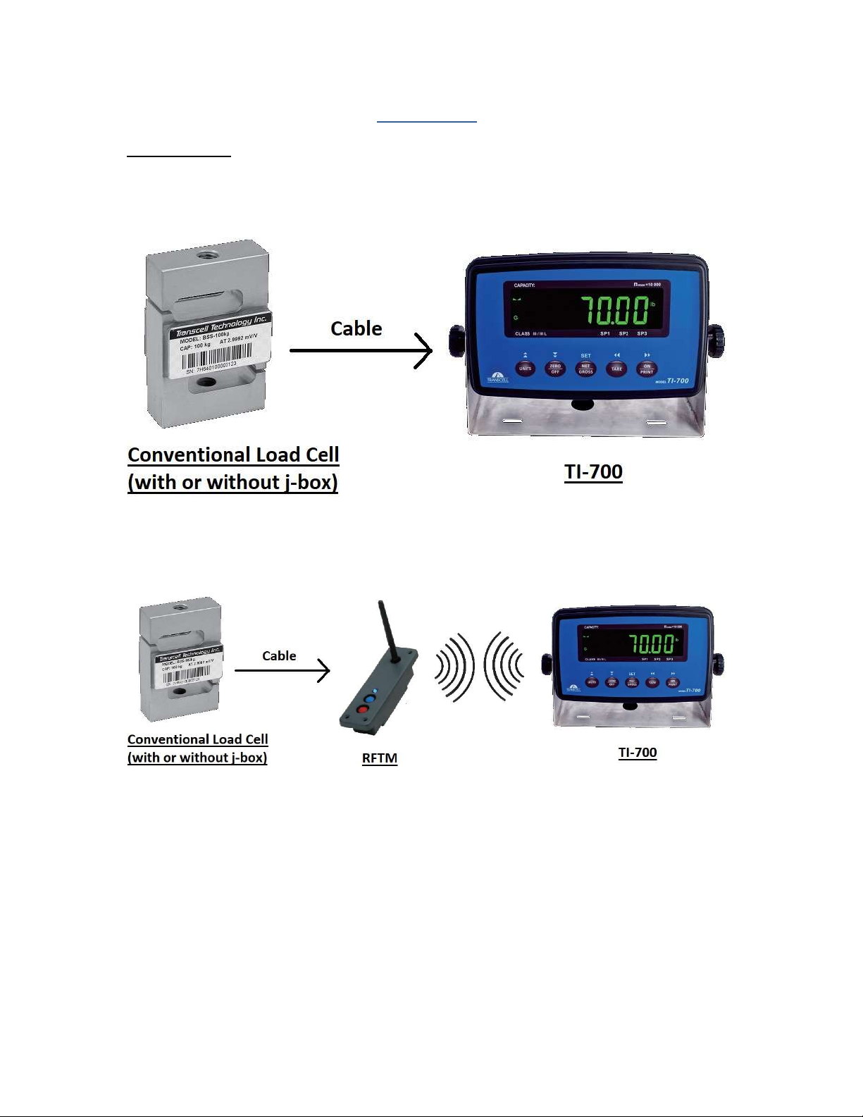
Out of the box, the TI-700 indicator operates as a basic, cabled digital weight indicator. The load
cell(s) and/or j-box is connected to the indicator’s internal A/D convertor. This configuration is
depicted in the following diagram:
When sold with an external TI-500 RFTM (Radio Frequency Transceiver Module) and an op-
tional wireless radio, your TI-700 indicator is transformed from “wired” to cable-free. This config-
uration is depicted in the following diagram:
Our products currently use reliable and popular Bluetooth® wireless technology.
This manual covers operation and troubleshooting. For installation, configuration and calibration
of the RF indicators please refer to the separate installer’s guide.
4
BASIC OPERATION
Getting Started – Cabled Systems
1. Press and hold the ON/PRINT key on the digital indicator unit for two seconds.
After a brief initialization period, the scale will revert to a zero (“0”) weight display.
Your scale is now ready for operation!
Getting Started – Wireless Systems
1. Switch on the TI-500RFTM weighing module(s) by pressing the BLUE button once. The
blue LED will turn solid for a few seconds and then start to flash.
2. Next press and hold the ON/PRINT key on the digital indicator unit for two seconds.
After a brief initialization period, the scale will revert to a zero (“0”) weight display.
Your wireless scale is now ready for operation!
Operation – TI-700
Before weighing it is necessary to check if the scale is unloaded and indicating zero weight in
the desired unit of measure, for example lb for pounds.
If the indicator is not displaying the desired unit of measure, press the UNITS key repeatedly un-
til it is indicated, e.g. lb for pounds, kg for kilograms, etc.
The indicator features an automatic zero correction meaning that small deviations will be zeroed
automatically. If the indicator does not automatically determine the zero point, please press the
ZERO/OFF key once briefly.
Operation – TI-500 RFTM
The TI-500 RFTM contains two buttons and one LED.
The BLUE button is used to power up the RF weighing module
The RED button is used to immediately power down the RF weighing module
The TI-500 RFTM has several operating modes to save battery life and also to alert the user
when it’s time to replace the batteries. You can determine the operating mode by observing the
blinking behavior of the blue LED:
LED Functionality
–
Blinking interval
During Power-up (Initialization) ON for 5 seconds
FULL BATTERY Blink interval
Working Mode 1.5 seconds
Sleep Mode (power savings) 4 seconds
LOW BATTERY Blink interval
Working Mode 10 seconds Double Flash
Sleep Mode 10 seconds Double Flash
Please replace the batteries when the blink interval is 10 seconds!

5
NOTE 1: TI-500 RFTM will shut down completely within two hours of a lost connection with the
indicator.
NOTE: 2: TI-500 RFTM will only enter sleep mode when the TI-700 indicator is OFF.
When shipped from the factory, the TI-700 digital indicator is configured to automatically switch
off after 5 minutes if not in use.
Replacing the batteries – TI-500 RFTM
An optional cylindrical battery holder is available which requires 4 “C” cell alkaline batteries.
1. Turn the TI-500 RFTM OFF (Press the RED button)
2. Locate the metal battery cylinder
3. Unscrew either end cap to reveal batteries
4. Exchange the batteries – be careful to note polarity
5. Replace the end cap
6. Re-install the metal battery cylinder
Optional Rechargeable battery information
The TI-700 may contain an optional rechargeable battery which is internal to the unit. Before us-
ing the indicator for the first time, please charge the battery overnight.
The indicator’s battery should operate for about 85 hours if left on continuously. The display unit
is configured to power down after 5 minutes of inactivity but this parameter can be changed thru
the A1-10 menu setting.
The battery can be charged while ON or OFF and the indicator can be operated while it’s charg-
ing unless the state of charge is very low.
WHEN TO CHARGE THE INTERNAL BATTERY
The best time to charge the Lithium Ion battery is any time the indicator is not in use. You need
not wait for the Low Battery Indication – in fact it’s best that you don’t. Charging the battery
when not in use keeps the battery “fresh” and is the recommended way to manage it.
When the battery needs to be charged, the Low Battery Indicator will start blinking in the lower
left-hand corner of the display. The indicator may be used for an additional 2 minutes before it
automatically powers down. It is imperative that you charge the battery at this time to avoid
permanent damage.
6
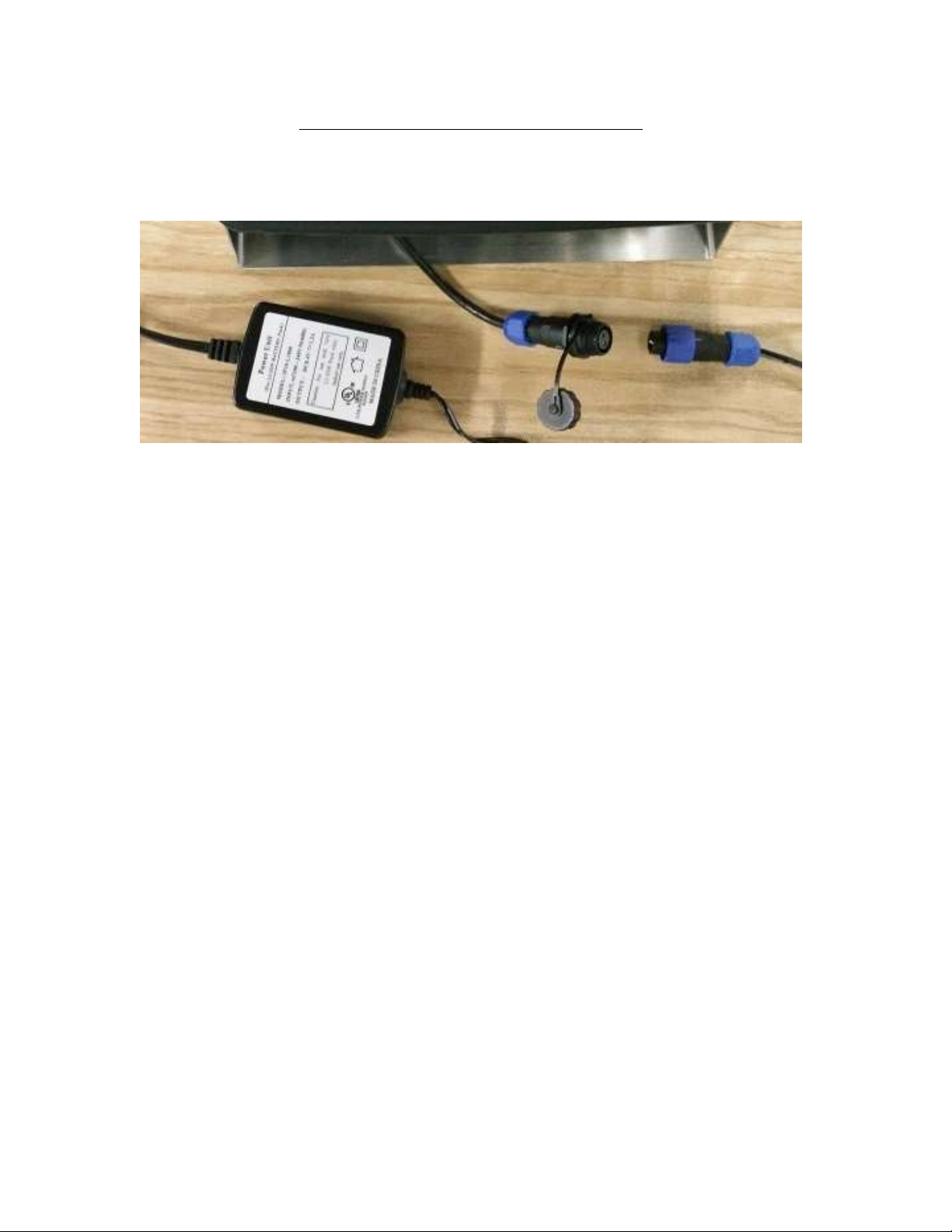
HOW TO CHARGE THE INTERNAL BATTERY
This version ships with a pre-installed power connector and an external battery charger. Simply
link the two up, and plug the battery charger into a suitable AC wall outlet. Note that the external
battery charger is rated for IP54 only.
Balance of this page intentionally left blank
7
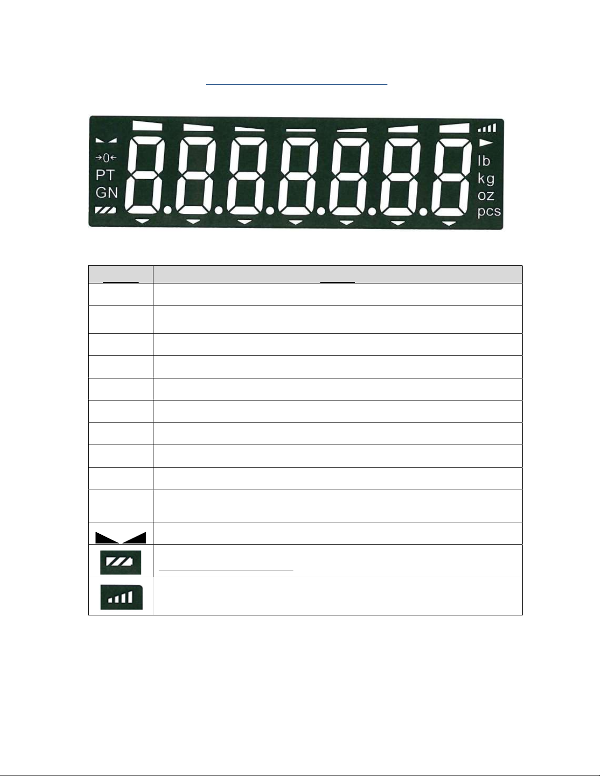
DISPLAY & KEYPAD DETAILS
This model utilizes a 7-digit reverse LCD (Liquid Crystal Display) with adjustable LED backlight.
The Table below summarizes the display annunciators:
Symbol
Display
0 Indicates that the scale is on Zero.
N Indicates that the indicator is displaying net weight (Gross weight minus Tare weigh).
G
Indicates that the indicator is displaying gross weight
T Indicates that a push-button tare weight has been established in the system
P
Indicates that the indicator is in PEAK HOLD mode
lb Indicates that the unit of the displayed weight is in pounds
kg Indicates that the unit of the displayed weight is in kilograms
g Indicates that the unit of the displayed weight is in grams
oz Indicates that the unit of the displayed weight is in ounces
pcs Indicates that the scale is in piece count mode and is displaying the current number of pieces
on the platform
This light is on whenever the scale is at rest (stable reading).
Indicates approximate battery charge remaining. When blinking, indicates that the battery
needs to be recharged or replaced soon.
Indicates wireless signal strength

8
The capacitive touch keypad is composed of a total of five (5) function keys.
Keypad Functions
Units
This key toggles the indicator between lb and kg.
Zero/Off This key sets the indicator to display zero weight provided the following conditions
are met:
1. The indicator is displaying Gross weight.
2. The scale is not in motion.
3. The scale is not in overload (see error codes).
Press and hold for five seconds to shut the unit OFF.
Net/Gross This key toggles the indicator between Gross weight and Net weight - but only if a
Tare weight has been established first
Tare This key is used to establish a Tare weight provided the following conditions are
met:
1. The indicator is displaying a Gross weight above zero.
2. The scale is not in motion.
3. The scale is not in overload (see error codes).
If a tare weight has already been established, this key cancels the current tare
weight.
On/Print Press and hold for two seconds to turn the unit ON. When the unit is on, this key
is used to send weight information out to the serial port provided the following con-
ditions are met:
1. The scale is not in motion.
2. The scale is not in overload (see error codes).
SET &
arrows
Utilized in the various configuration menus (see installer guide for more infor-
mation)

9
ADVANCED OPERATION
Hold operation:
This mode of operation is enabled by setting F30 to “5” in the Setup Menu (see separate in-
staller’s guide for more information). This mode captures the weight of an unstable load, e.g.
livestock, by freezing the weight on the display. Use the Motion Band setting (F5) and the Per-
centage Hold setting (F36) to adjust this mode to your specific application. When the weight has
been locked onto the display, two arrows beneath the weight display will be turned ON.
There are several specific hold modes, which are selected thru the F35 setting.
AUTOMATIC (F35 = 1) – Automatically locks weight on the display when stable. If the weight of
the object on the scale changes by the F36 setting (e.g. 10%) then the sale unlocks the held
reading and relocks onto the new weight. This occurs during both increasing and decreasing
weight values.
MANUAL (F35 = 2) – Press the NET/GROSS key before applying any weight to the scale. After
the load has stabilized, the display will hold the weight reading on the screen until the
NET/GROSS key is pressed again. If the weight of the object on the scale changes by the F36
setting (e.g. 10%) then the sale unlocks the held reading and relocks onto the new weight. This
occurs during increasing weight values only.
PEAK HOLD (F35 = 3) – The display updates as the load increases but not as the load de-
creases. The value shown on the screen is the maximum weight applied to the scale. Press the
UNITS key to toggle between live mode and peak hold mode. The ‘P’ annunciator is used to in-
dicate that you are in Peak Hold mode. When you exit out of peak hold mode, the old peak
value is automatically cleared.
NET Weighing
Gross weight refers to the total weight of a product and its packaging. Conversely, net weight
refers to the weight of the product alone, discounting the weight of its container or packaging;
and tare weight is the weight of the packaging alone.
NOTE: This indicator stores the current tare weight in memory if the indicator is properly pow-
ered OFF. If a tare weight is present at startup, the indicator will revert to NET weighing mode
and apply the stored tare weight.
1. If weighing an item in a container, place the empty container onto the scale’s platter
2. After allowing the weight indication to stabilize, press the TARE key.
The display shows zero weight and the NET annunciator is activated
3. Place the object to be weighed on the scale’s platter and allow the weight indication to
stabilize.
The reading shown is the net value of the applied load
4. If necessary, toggle between the gross weight and the net weight by pressing the
NET/GROSS key
5. Press the TARE key again to clear the tare value and return to gross weighing mode

10
Piece Counting
IMPORTANT NOTE: The piece counting function cannot be used in commercial (NTEP) appli-
cations.
This mode of operation is enabled by setting F30 to “3” in the Setup Menu (see separate in-
staller’s guide for more information). This mode is used to indicate the number of pieces of an
item you have placed on the scale’s platform and is accessed by pressing the UNITS key. To
ensure accuracy, the parts you are counting must be consistent in weight.
The indicator uses the sampling method to determine the average piece weight (APW) of the
items you wish to count. When sampling items, always count the parts in your hand and place
them on the platform all at once. If the APW of the items is too light or the total weight of the
sample is too light, accuracy cannot be guaranteed. You will get an error message, but piece
counting will still be allowed. This indicator does not retain the piece weight when powered
down.
1. If the items you will be counting require a container, you must first tare the container off by
pressing the TARE key.
NOTE: The TARE key is inoperative when in sampling mode.
2. Press the UNITS key until “5 0” is indicated on the display. If the screen does not show “5
0”, press the ZERO key once. The indicator is prompting you to place five identical items on
the platform.
NOTE: If you wish to change the sample number, simply press the UNITS key repeatedly
until the desired sample number appears. Available choices are 5, 10, 20, 50 and 100. If
you continue to push the UNITS key, the indicator will resort back to weighing mode and
you must start again from Step 2.
3. Place the sample items on the platform all at once and allow the weight indication to stabi-
lize. Once this is done, the zero indicated after the sample number will change to a “–“. For
example, “5 –“.
4. Press the NET/GROSS key to take the sample. If the sample size is large enough, the indi-
cator now displays the number of pieces on the platform and the “PCS” annunciator is lit. If
not, the indicator briefly displays “Lo” and automatically increments the sample size. Repeat
Step #4 with the new sample size.
NOTE: If the indicator continues to display “Lo” even after sampling 100 pieces, the unit
weight of the items you wish to count is too light for your scale to process accurately.
5. To exit the piece count mode, press the UNITS key.
NOTE: The APW will NOT remain in scale memory when you exit piece counting mode.
Peak Hold Mode
IMPORTANT NOTE: The peak hold function cannot be used in commercial (NTEP) appli-
cations.
This mode of operation is enabled by setting F30 to “5” in the Setup Menu and F35 to “3” in the
User Menu (see separate installer’s guide for more information). This mode is used to indicate
and hold the peak weight recorded during a specific process. The most common application is
testing the breaking point of a part or assembly. The TI-700 records both positive and negative
peak weights.
1. Push the UNITS key to active peak hold mode; the “P” annunciator turns ON.
2. Apply force to the piece – the display indicates and holds the peak force applied.

11
3. To toggle between positive and negative peak weights, use the NET/GROSS key.
4. To reset both peak values to zero, press the ZERO key.
5. To exit peak hold mode, press the UNITS key again; the “P” annunciator turns OFF.
Accumulation (Totaling)
This mode of operation is enabled by setting F30 to “1” in the Setup Menu (see separate in-
staller’s guide for more information). The mode allows you to add weighments together to obtain
a total weight. When a tare weight is active, the net weight is added automatically.
1. Load the system with the weight that is to be added.
2. Press the ON/PRINT key to add the current load to the weight accumulator.
3. The display briefly shows the message “ADDED” and then automatically returns to the
weighing mode.
4. If a printer is installed, a printout will be made. The gross, net and tare weights are to-
taled.
5. No weight can be recorded twice. The system needs to be returned to the net zero-
range before another weight can be added.
6. The subtotal can be checked by pressing the ON/PRINT key for 3 seconds.
The display shows the net total weight and the number of weightings totaled so far re-
peatedly for 3 seconds.
7. If the PRINT key is pressed briefly during this period, the total is printed (if option is in-
stalled) and reset to 0.
8. If the PRINT key is pressed and held for 3 seconds during this period, the total is reset
but not printed.
9. If no key is pressed during this period, the subtotal stays in memory and the system re-
turns to the weighing mode after 60 seconds.
Printer
If the weighing system has been equipped with a printer, then weighing and time & date data
can be printed.
Here is an example of a possible printout:
ID.NO. 123456
DATE 01/28/11
TIME 10:23 AM
GROSS 1067 lb
TARE 67 lb
NET 1000 lb
PCS 1000
NOTES:
1. Some fields may not appear on your printout, depending upon your configuration
settings
2. The TARE and NET fields are printed only when a tare has been established in the
system.

12
Adjusting the Time and Date on the Printout
Your indicator will keep track of the current time and date for you, which can then be printed on
the print ticket. To adjust the time and date, you must first enter the User Menu Mode.
1. Switch off the RF digital indicator by pressing and holding down the ZERO/OFF key for
about 5 seconds.
2. Press and hold down the ON/PRINT key (about 20 seconds) until the screen shows
“-F-”.
3. Press the ON/PRINT (right) key once. The screen displays “-A-”.
4. Scroll down using the ZERO/OFF (down) key to reach the parameter level. The scale shows
“A1-1”.
5. Move from A1-1 to A1-20 by pressing the TARE (left) key repeatedly until the screen shows
“A1-20”.
6. Once you have arrived at A1-20 press the ZERO/OFF (down) key once. The screen dis-
plays “ho_xx” where ‘xx’ is the current hour, e.g. “15”. One digit will be flashing.
7. Use the four directional keys to adjust the displayed value to the actual hour value. Increase
the flashing digit by pressing the UNITS key. Decrease the flashing digit by pressing the
ZERO/OFF key. Pressing the TARE key or the ON/PRINT key will change the position of
the flashing digit.
8. After entering the exact value, press the NET/GROSS key to save the value. The screen
displays “n¬_xx” where ‘xx’ is the current minute, e.g. “55”. One digit will be flashing.
9. Use the four directional keys to adjust the displayed value to the actual minute value. In-
crease the flashing digit by pressing the UNITS key. Decrease the flashing digit by pressing
the ZERO/OFF key. Pressing the TARE key or the ON/PRINT key will change the position
of the flashing digit.
10. After entering the exact value, press the NET/GROSS key to save the value. The screen
displays “dA_xx” where ‘xx’ is the current day of the month, e.g. “14”. One digit will be flash-
ing.
11. Use the four directional keys to adjust the displayed value to the actual day value. Increase
the flashing digit by pressing the UNITS key. Decrease the flashing digit by pressing the
ZERO/OFF key. Pressing the TARE key or the ON/PRINT key will change the position of
the flashing digit.
12. After entering the exact value, press the NET/GROSS key to save the value. The screen
displays “n¬_xx” where ‘xx’ is the current month of the year, e.g. “02”. One digit will be flash-
ing.
13. Use the four directional keys to adjust the displayed value to the actual month value. In-
crease the flashing digit by pressing the UNITS key. Decrease the flashing digit by pressing
the ZERO/OFF key. Pressing the TARE key or the ON/PRINT key will change the position
of the flashing digit.
14. After entering the exact value, press the NET/GROSS key to save the value. The screen
displays “yE_xx” where ‘xx’ is the current month of the year, e.g. “11”. One digit will be flash-
ing.
15. Use the four directional keys to adjust the displayed value to the actual year value. Increase
the flashing digit by pressing the UNITS key. Decrease the flashing digit by pressing the
ZERO/OFF key. Pressing the TARE key or the ON/PRINT key will change the position of
the flashing digit.

13
16. After entering the exact value, press the NET/GROSS key to save the value and revert back
up to the parameter level, e.g. ”A1-20”.
Checkweigher
NOTE: If you wish to drive a light tree or a set of buzzers/alarms, then this mode requires an op-
tional digital I/O board. Use the A1-25 menu to set the logic of the outputs.
Optional Digital I/O
3 out
1 in
Logic level only (i.e. external relays are required to drive big loads)
This mode of operation is enabled by setting F30 to “6” in the Setup Menu (see separate in-
staller’s guide for more information). The mode allows you to accurately fill a vessel by weight.
For the operator, the only thing to do is to set the Low and High (Min/Max) weight values. This
can be done from the front panel:
High/Low (Min/Max) Set Points
To enter new high/low (min/max) set point weight values:
1. Press the NET/GROSS key.
The display briefly shows “Lo” followed by the current low weight value with one digit
blinking. The pointer for SP1 is lit.
2. Use the four directional keys to adjust the displayed value to the desired low weight
value. Increase the flashing digit by pressing the UNITS key. Decrease the flashing
digit by pressing the ZERO/OFF key. Pressing the TARE key or the ON/PRINT key
will change the position of the flashing digit.
3. After entering the exact value, press the NET/GROSS key to save the value.
The screen displays “SET” and then “Hi” briefly, followed by the current high weight
value with one digit blinking. The pointer for SP3 is lit.
4. Use the four directional keys to adjust the displayed value to the desired high weight
value. Increase the flashing digit by pressing the UNITS key. Decrease the flashing
digit by pressing the ZERO/OFF key. Pressing the TARE key or the ON/PRINT key
will change the position of the flashing digit.
5. After entering the exact value, press the NET/GROSS key to save the value.
The screen displays “SET” briefly. The high/low weight values are activated and the
display returns to the weighing mode.
Balance of page intentionally left blank

14
TI-700 checkweigher operation:
If the displayed weight (net or gross) is less than the Low (Min) value, then:
Digital Output #1 is activated
SP1 light is ON
Backlight colors is BLUE
If the displayed weight (net or gross) is more than the High (Max) value, then:
Digital Output #3 is activated
SP3 light is ON
Backlight colors is RED
If the displayed weight (net or gross) is within the low / high (Max /Min) range, then:
Digital Output #2 is activated
SP2 light is ON
Backlight colors is GREEN

15
ERROR MESSAGES
Indicates that the weighing capacity of the scale
has been exceeded.
Indicates that the weight on the scale is negative.
Press the Zero/Off key.
TI-500 RFTM #1 not found; ensure that it is pow-
ered ON or move it closer to the digital indicator.
WIRELESS SYSTEMS ONLY
NOTE: Dual systems only
TI-500 RFTM #2 not found; ensure that it is pow-
ered ON or move it closer to the digital indicator.
WIRELESS SYSTEMS ONLY
TI-500 RFTM #1 batteries have been depleted and
need to be replaced. WIRELESS SYSTEMS ONLY
TI-500 RFTM #2 batteries have been depleted and
need to be replaced. WIRELESS SYSTEMS ONLY
Both TI-500 RFTM #1 and #2 batteries have been
depleted and need to be replaced. WIRELESS
SYSTEMS ONLY
Battery in TI-700 indicator need to be recharged or
replaced.
Battery in digital indicator need to be recharged or
replaced and TI-500 RFTM #1 batteries need to be
replaced.
Battery in digital indicator need to be recharged or
replaced and TI-500 RFTM #2 batteries need to be
replaced.

16
Battery in digital indicator need to be recharged or
replaced and both TI-500 RFTM batteries need to
be replaced.
Err 24 Value for SP1 is greater than value for SP2.
Err 99 Parameter menus blocked. Toggle calibration
switch back to its original position.
No-ad Weighing platform not detected
SPECIFICATIONS
Digital Indicator Specifications – TI-700
- ABS enclosure rated for IP67
- 1.0”, 7-digit reverse LCD w/LED backlight
- Operating temperature -4°F to 104°F (-20°C to 40°C)
- Internal connection port for optional printer
- Tilt adjustable bracket included
- AC Power: 90-308 VAC, 50/60 Hz
- DC Power: 5-15 VDC
OPTIONAL Bluetooth Specifications (RFTM)
- 2.0, Class I
- Up to 100m unobstructed
- (ISM) band at 2.4 to 2.485 GHz
Optional Digital Indicator Battery – TI-700
- 7.4 volt 3 Ah internal Li-Ion rechargeable battery
- 85+ continuous hours of operation on full charge under typical operating conditions
OPTIONAL TI-500 RFTM Battery Holder
- Holds 1.5-volt x 4 “C” alkaline
- User replaceable
- 130+ continuous hours of operation under typical operating conditions

17
TROUBLESHOOTING
Issue / Recommendation
“Low Battery” icon blinks on the digital readout, then the indicator powers off.
Replace or recharge the batteries.
Weight reads out lower at one end of the weighing platform than the other end.
- Check for any type of mechanical binding or impingement of scale that is displaying the
lower weight
- Check underneath the scale for any obstructions or foreign debris
- Make sure that the scale feet are not screwed in so far as to restrict downward move-
ment of the scale.
- Adjust platform corners using variable trimmer junction box (if supplied)
Indicator displays seven small zeros.
- Scale is overloaded. Remove weight from scale.
- Cut, damaged, loose, pinched cable between indicator and platform or within platform
with multiple load cells (*cabled configuration only)
- Load cell damaged on platform
- Internal fault with indicator; call Transcell Tech Support
Scale turns off on its own.
The indicator has a power conservation feature, set to automatically power off the scale after 30
minutes of non-use. If your needs require a different setting, call Transcell Tech Support or in-
staller.
Display is erratic.
- A battery may be fully depleted. If so, this condition can cause erratic displays. Power
off the indicator and replace or recharge the battery.
- Check underneath the scale for any obstructions or foreign debris
Transcell Tech Support: (847) 419-9180
Limited 12-month Warranty
This product is warranted by Transcell Technology against manufacturing defects in material and
workmanship under normal use for twelve (12) months from the date of purchase. For complete
warranty details and service information, please contact us at the address below.
Transcell Technology, Inc.
975 Deerfield Parkway
Buffalo Grove, IL 60089
Tel (847) 419-9180
Fax (847) 419-1515
Web: www.transcell.com
Table of contents
Other Transcell Technology Accessories manuals

Transcell Technology
Transcell Technology TI-1520 User manual

Transcell Technology
Transcell Technology TI-500E User manual

Transcell Technology
Transcell Technology TI-500 Plus Parts list manual

Transcell Technology
Transcell Technology TI-700K User manual

Transcell Technology
Transcell Technology TI-700K User guide

Transcell Technology
Transcell Technology TI-1200 Series Parts list manual


