Transcell Technology TI-700K User guide

MODEL
TI-700K
Digital Weight Indicator
(with wireless weighing capability)
Installer’s
Manual
Revision 1.7a March 09, 2020

1
©Transcell Technology, Inc. 2016-2020. All rights reserved.
The information contained herein is the property of Transcell Technology and is supplied without liability for errors or
omissions. No part may be reproduced or used except as authorized by contract or other written permission. The copy-
right and the foregoing restriction on reproduction and use extend to all media in which the information may be embod-
ied.
Contents subject to change without notice.
Contents
INSTALLATION & OVERVIEW..................................................................................................... 2
SCOPE OF TI-700K .................................................................................................................. 2
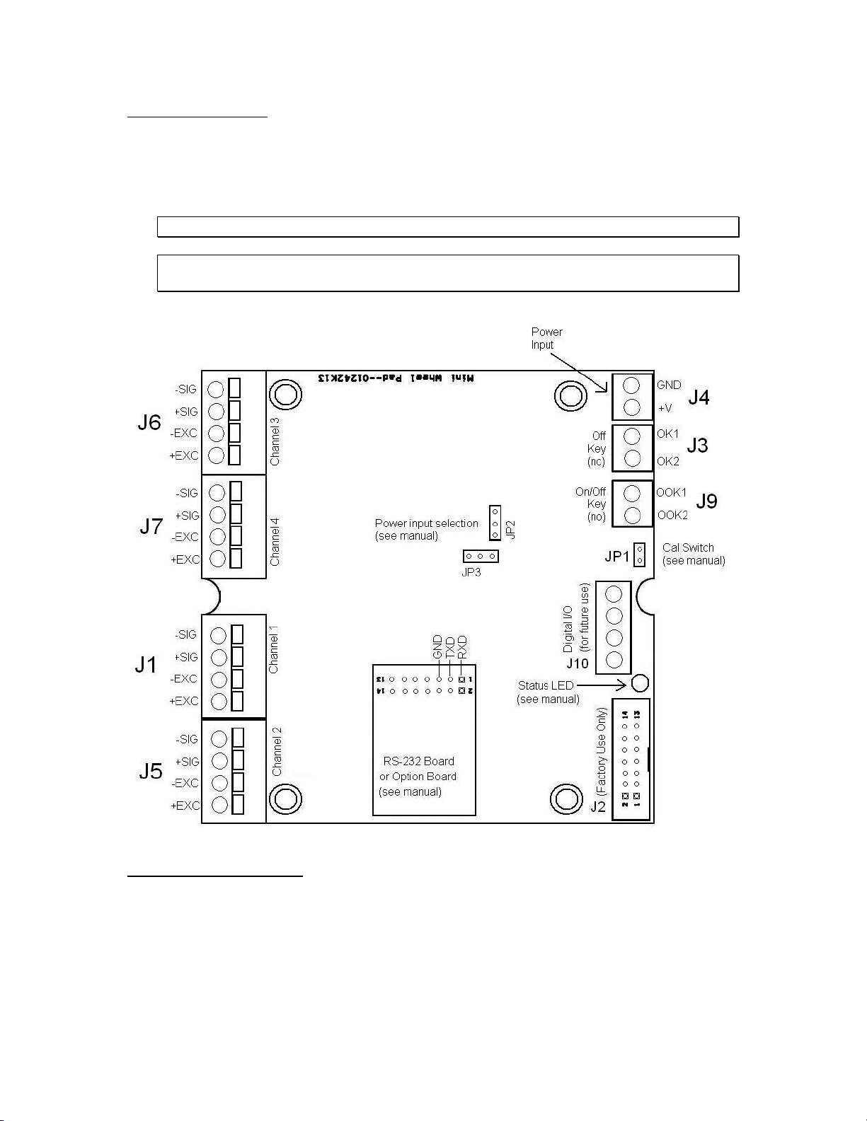
INSTALLATION OF TI-700K DIGITAL INDICATOR ................................................................. 3
RS-232 CONNECTIONS (COM1)............................................................................................. 5
POWER CONNECTIONS (AC VERSION)................................................................................ 5
POWER CONNECTIONS (OPTIONAL RECHARGEABLE BATTERY VERSION).................. 5
USB PORT................................................................................................................................. 6
INSTALLATION OF TI-500 RFTM REMOTE WIRELESS A/D MODULE................................. 6
INSTALLATION OF LCT-1 REMOTE WIRELESS DIGITAL JUNCTION BOX......................... 8
GETTING STARTED –CABLED SYSTEMS ..........................................................................10
GETTING STARTED –WIRELESS SYSTEMS......................................................................10
SYSTEM CONFIGURATION.......................................................................................................11
CONFIGURATION MENUS..................................................................................................... 11
ENTERING THE SETUP (“F”) CONFIGURATION MENU......................................................12
SETUP (“F”) MENU DESCRIPTIONS ..................................................................................... 12
ENTERING THE USER/COM1 (“A1”) MENU.......................................................................... 17
USER/COM1 (“A1”) MENU DESCRIPTIONS ......................................................................... 18
SETTING SYSTEM TIME AND DATE (A1-20) .......................................................................20
DIAGNOSTICS (A1-24)........................................................................................................... 21
ENTERING THE COM2 (“A2”) MENU.....................................................................................22
COM2 (“A2”) MENU DESCRIPTIONS .................................................................................... 22
SCALE SYSTEM CALIBRATION................................................................................................24
CALIBRATION OVERVIEW .................................................................................................... 24
DIGITAL ZERO/SPAN CALIBRATION (F16 AND F17) ..........................................................24
KEY-IN ZERO CALIBRATION VALUE (F19) .......................................................................... 25
KEY-IN SPAN CALIBRATION VALUE (F20) ..........................................................................25
MV/V SPAN CALIBRATION (F52)...........................................................................................26
SERIAL PORT INFO ................................................................................................................... 28
SERIAL PORT MODES........................................................................................................... 28
OUTPUT STRINGS................................................................................................................. 29
“CE” logo here somewhere…

2
INSTALLATION & OVERVIEW
Remember that the installer is ultimately responsible to assure that an installa-
tion will be and remain safe and operable under the specific conditions encoun-
tered.
This manual covers the following products:
Model
Display
Enclosure
Power Source
TI-700K
LCD
ABS
90-308 VAC, 50/60 Hz
TI-500 RFTM-B2
None
ABS
4-14 VDC
TI-500 RFTM-B2E
None
ABS
4-14 VDC
LCT-1
None
ABS
4-14 VDC
A factory installed rechargeable battery option is also available.
Scope of TI-700K
Out of the box, the TI-700K indicator operates as a basic, cabled digital weight indicator. The
load cell(s) and/or j-box is connected to the indicator’s internal A/D convertor. This configuration
is depicted in the following diagram:
When sold as part of a Smarter Weigh™RF Kit, your TI-700K indicator is transformed from
“wired” to cable-free, as depicted in the following diagram:

3
NOTE: A wireless LCT-1 junction box can be substituted for the RFTM in the above diagram.
Our products currently use reliable and popular Bluetooth® wireless technology.
This manual covers installation, configuration and calibration of the RF scale system. For opera-
tion and troubleshooting, please refer to the separate user’s guide.
Installation of TI-700K digital indicator
Find a suitable location for the indicator and use the included bracket to mount the unit to a wall
or table. Use this handy guide for mounting the bracket to a wall or table:
CONNECTIONS
The rear cover must first be removed to make the appropriate connections to the weigh plat-
form, etc. To remove the rear cover, simply remove the screws that secure it to the enclosure
and set aside.
Caution! Disconnect power source from indicator prior to removing rear cover.
Caution! Disconnect leads from rechargeable battery (if installed) to avoid shorts!

4
Load Cell Connections
Connect your shielded load cell cable to terminal block J1 using the table below. All terminals
are labeled for function.
TIP: You should have the color codes handy for your load cell / junction box / weighing platform
before doing so.
Load Cell Terminal Block J1
Marking
Function
Marking
Function
GND
Shield
S-
- Signal
E+
+ Excitation
SE-
- Sense
SE+
+ Sense
E-
- Excitation
S+
+ Signal
NOTE1: Use F11 to configure for 4-wire or 6-wire load cells
NOTE2: Pins 1 and 2 are for DC power input (V+ and V–respectively) …
NOTE3: There are two configurations for J1, as shown above, and differing only in the location
of the load cell shield wire connection (GND)

5
RS-232 Connections (COM1)
The indicator ships with a “piggyback” RS-232 communication board plugged into socket U9
(COM1). This port is configured via the User/COM1 (“A1”) menu.
Connect your RS-232 serial communications cable to said “piggyback” board using the table be-
low. Pin 1 is on the left.
COM1 RS-232 Terminal Block (J6)
Pin No.
Function
1
Receive Data
2
Transmit Data
3
Signal Ground
Power Connections (AC version)
The TI-700K indicator ships with a pre-installed AC line cord. It has been pre-wired to Terminal
Block J1 at the factory. Simply plug the unit into a standard wall outlet.
Power Connections (Optional Rechargeable Battery version)
The TI-700K with rechargeable battery ships with a pre-installed battery charger connector and
an external battery charger. Simply link the two up and plug the external battery charger into a
suitable AC wall outlet.
External Battery Charger

6
To prolong battery life, disconnect the external battery charger from the unit when charg-
ing is complete (Green LED).
Caution: the external battery charger is rated for IP54 only and exposure to water may
void the warranty. Be sure to remove the battery charger from the indicator and apply the cap
to the battery charger connector before washing it down.
USB Port
The external USB port is used for updating of the firmware only. Consult factory for use.
Installation of TI-500 RFTM remote wireless A/D Module
Physical installation
The remote wireless A/D module is designed to fit into a pre-defined opening:
An optional mounting bracket is also available.

7
Electrical Connections
The TI-500 RFTM module requires an external 6VDC power supply. Single channel units re-
quire about 60 mA of current to drive four 350-ohm load cells (20 mA plus 10 mA per load cell).
Dual channel units require about 100 mA of current to drive eight 350-ohm load cells.
The TI-500 RFTM module will operate normally down to approximately 4 VDC whereupon it will
indicate a low battery condition.
The power leads are pre-wired to the inside of the TI-500 RFTM. The red lead goes to the posi-
tive DC terminal while the black lead goes to the negative DC terminal.
The TI-500 RFTM module also has at least one load cell input terminal or wiring harness. Each
terminal or harness can drive up to four 350-ohm load cells. The terminals are spring loaded; to
open, use a small screwdriver to press down on the orange tab. The harnesses should be
spliced to the load cell or j-box using the supplied butt splices.
Load Cell Input Terminal
Marking
Wire Name
Marking
Wire Name
S-
- Signal
E-
- Excitation
S+
+ Signal
E+
+ Excitation
NOTE: On dual RF A/D modules, each load cell terminal is marked 1-4, e.g. L/C3.
Load Cell Input Harness
Wire Color
Wire Name
Wire Color
Wire Name
White
- Signal
Black
- Excitation
Green
+ Signal
Red
+ Excitation

8
Installation of LCT-1 remote wireless digital junction box
Physical installation
Find a suitable location for the digital junction box and use the mounting tabs to mount the unit
to a wall or table. The junction box may be mounted vertically or horizontally. Use this handy
guide for mounting the box to a wall or table:

9
Electrical Connections
The top cover must first be removed to make the appropriate connections to the weigh platform.
To remove the top cover, simply remove the six (6) screws that secure it to the enclosure and
set aside.
Caution! Disconnect power source from junction box prior to removing top cover.
Note: If the optional control panel was ordered, you need not make connections to the
LCT-1 for power supply, serial device or on/off control
Connecting your load cell(s)
The LCT-1 contains four connection terminals on the main board –one for each load cell:
1. LC1: J1
2. LC2: J5
3. LC3: J6
4. LC4: J7

10
Connect your load cell cable (not included) to the appropriate terminal on the main board.
Caution! Strip each load cell wire back 10 mm and tin before inserting into the spring-
loaded terminals.
Load Cell Terminals (J1, J5, J6 and J7)
Label
Function
S-
- Signal
S+
+ Signal
E-
- Excitation
E+
+ Excitation
Caution! If connecting less than four load cells to the LCT-1, then the S+ and S- terminals
must be shunted with a jumper wire on each unused load cell input terminal
Getting Started –Cabled Systems
1. Press and hold the ON key on the digital indicator unit for two seconds.
After a brief initialization period, the scale will revert to a zero (“0”) weight display.
Your digital indicator is now ready for configuration and system calibration.
Getting Started –Wireless Systems
1. Switch on the TI-500 RFTM remote wireless A/D module(s) by pressing the BLUE but-
ton once. The blue LED will turn solid for a few seconds and then start to flash.
2. Next press and hold the ON key on the digital indicator unit for two seconds.
After a brief initialization period, the scale will revert to a zero (“0”) weight display.
Your wireless digital indicator is now ready for configuration and system calibration.

SYSTEM CONFIGURATION
Configuration Menus
The TI-700K digital indicator contains three menus to configure the scale system:
Setup (“F”) Menu –Configures all scale-related parameters including calibration procedures.
User1 (“A1”) Menu –Configures COM1 communication parameters and other misc. parameters, e.g. automatic turn off and hold mode.
User2 (“A2”) Menu –Configures COM2 communication parameters.
The configuration menus are laid out in the following vertical arrangement:
•Top [Menu selection] level
•Parameter level
•Selection level (or function level, e.g. span calibration)
Please review the following chart to get a feel for how to navigate among the various menus and parameters.
Top
Level
-F-
-A1-
-A2-
Parame-
ter
F1
F3
Etc.
A1-1
A1-2
Etc.
A2-1
A2-2
Etc.
Level
Graduations
Zero Track Band
Baud Rate
Data, Parity, Stop Bits
Baud Rate
Data, Parity, Stop
Bits
Selec-
tion
100 to 50000
0, 0.25, 0.5, 1, 3, 5
600, 1200, 2400,
4800, 9600, 19200
8_n_1, 8_n_2, 7_n_1,
7_n_2, 7_E_1, 7_E_2,
7_o_1, 7_o_2
600, 1200, 2400,
4800, 9600, 19200
8_n_1, 8_n_2,
7_n_1, 7_n_2,
7_E_1, 7_E_2,
7_o_1, 7_o_2
Level
NOTE: The -C- menu appears in place of the -B- menu for cabled systems.

Entering the Setup (“F”) Configuration Menu
To access this menu, please follow these directions:
1. Press and hold the MENU/OFF key to switch off the digital indicator.
2. Press and hold the ON key until the digital indicator beeps and starts to boot up.
3. During the countdown phase (“555555, 444444”, etc.) press and hold the MENU/OFF key
until the “Set?” message is displayed.
4. Press the NET/GROSS button while “Set?” is being displayed. The digital indicator displays
“- F –“.
5. Scroll down using the ZERO (down) key to reach the parameter level. The scale shows “F
1”.
6. Move from one “F” menu parameter to the next by using the TARE (left) or PRINT (right) keys.
For example, to go from F1 to F2, press the PRINT key. To go from F2 back to F1, press the
TARE key.
7. Once you have arrived at the proper “F” menu parameter, e.g. ”F1”, press the
ZERO (down) key once to arrive at the selection level. The scale displays the current param-
eter setting.
8. If there is a selection list, scroll thru the available parameter settings, use the TARE (left) or
PRINT (right) keys. Otherwise, use the arrow keys to adjust the displayed value to the new
value.
9. Once the setting you want is displayed on the screen, press the NET/GROSS (set) key to
save this value and revert up to the parameter level, e.g. ”F 1”.
NOTE: If you see a “CAL-Err” message, the parameter changes were not saved. To allow
changes, you must open the unit and shunt jumper JP1.
Setup (“F”) Menu Descriptions
This section provides more detailed descriptions of the selections found in the Setup Menu Chart.
Factory-set defaults are shown in bold with a checkmark; (√).
CODE/NAME
DESCRIPTION
SELECTION LIST
F1
Graduations
Specifies number of full-scale graduations, i.e. capacity / division.
Value should be consistent with legal regulations and environmental
limits on the useful system resolution. Pressing the ZERO key to scroll
down one level begins the sequence.
Key-in
100 - 100000
10000
F2
Sampling Rate
Sets the sampling rate in Hertz (measurements per second).
NOTE 1: This menu is not applicable to wireless systems
NOTE 2: H2 = Hertz (Hz)
10, 20, 30, 50, 60,
80, 120, 150, 240,
400, 600, 1200
20 H2
F3
Zero Track
Band
Selects the range within which the scale will automatically zero. Note
that the scale must be in standstill to automatically zero. Selections are
in display divisions (d).
0 (Off)
0.5 1
3 5

13
CODE/NAME
DESCRIPTION
SELECTION LIST
F4
Zero Range
Selects the range within which the scale will accept a front panel
ZERO command. Note that the scale must be in standstill to automat-
ically zero. Selections are in display % of full scale. Pressing the
ZERO key to scroll down one level begins the sequence.
100
1.9
2
20
F5
Motion Band
Sets the level at which motion is detected. If motion is not detected,
the scale can process a Print orZero command. Maximum value varies
depending on local regulations. Expressed as scale divisions per sec-
ond (d/s). Pressing the ZERO key to scroll down one level begins the
sequence
Key-in
0.0 –32.0
1.0
F6
Digital Filter
Averages weight readings to produce higher stability. Choose the
speed that works best for your application.
"AUto" = Automatic, FIr = FIR (finite impulse response),
“Avg-xx” = Averaging Filter
Auto Flr
01, 04, 08, 16, 24,
32, 40, 48, 56, 64
F7
Overload Limit
Selects the desired formula which determines the point at which the
indicator shows overload. All selections are based on the primary unit
selected in F8. "FS" = Full scale capacity.
FS
FS + 2%
FS + 5%
FS + 1d
FS + 9d
F8
Calib. Unit
Selects the primary base unit to be used in the calibration process and
the default unit for normal operation.
"1" = primary unit is lb "2" = primary unit is in kg
1 2
F9
Display
Divisions
Determines the desired weight increments. Value should be consistent
with legal requirements.
1
2
5
F10
Decimal Point
Determines location of the decimal point.
0 00
0.0000 0.000
0.00 0.0
F11
No. of L/C
wires
Selects the number of wires on the load cell(s) to be connected to the
indicator. Cabled systems only.
"4" = four wires "6" = six wires (SENSE)
4 6
F12
Enable lb-oz
display
Allows you to enable or disable lb-oz display
"1" = lb-oz is enabled "0" = lb-oz is disabled
0
1
F14
Power-on zero
(IZSM)
Allows you to enable or disable power-on zero. (IZSM); max is 20%
of FS
"1" = IZSM is enabled "0" = IZSM is disabled
0
1
F15
Third unit se-
lection
Allows you to choose (select) the third unit of measure
"0" = third unit disabled "1" = grams (g)
"2" = ounces (oz)
0
1
2
F16
Zero Calibra-
tion
Places indicator into the zero-calibration routine. Scrolling down with
the ZERO key one level begins the procedure.
Press ZERO key
to begin sequence

14
CODE/NAME
DESCRIPTION
SELECTION LIST
F17
Span Calibra-
tion
Places indicator into the span calibration routine. Scrolling down with
the ZERO key one level begins the procedure.
Press ZERO key
to begin sequence
F18
View Calibra-
tion
Actuates the function that allows you to view both the zero and span
calibration value. The values displayed in this function are valid only
after Calibration (F16 & F17) has been successfully completed. Scroll-
ing down with the ZERO key one level begins the procedure.
Press ZERO key
to begin sequence
F19
Key-in Zero
Allows you to key-in known zero calibration value in case of memory
loss in the field. Scrolling down with the ZERO key one level begins
the procedure.
Press ZERO key
to begin sequence
F20
Key-in Span
Allows you to key-in a known span calibration value in case ofmemory
loss in the field. Scrolling down with the ZERO key one level begins
the procedure.
Press ZERO key
to begin sequence
F21
Factory Reset
This sub-menu will reset all parameters in the “F” and “A” menu to the
default settings. It will not overwrite any previously saved calibration
data. USE WITH CAUTION!
Press the ZERO
key twice to exe-
cute
F23
Fine Tune
4-20 mA
Actuates the function that allows you to fine-tune the optional
4-20 mA analog output. Pressing the ZERO key to scroll down one
level begins the sequence.
Press the ZERO
key to begin se-
quence
F24
Analog Output
Function
Selects the OPTIONAL active analog output function.
"oFF" = Off "4-20 nnA " = 4-20 mA "0–10u " = 0–10V
oFF
4-20 nnA
0–10u
F25
Set Point
Function
Selects the number and function of the set points and relay outputs.
See user’s guide for definitions
0 to 10
0
F26
Multi-interval
segments
Selects the number of weighing segments for multi-interval.
"0" = multi-interval is disabled
0
1
2
F27
No. of Scale
Divisions
(WS1)
Selects the number of scale divisions to be used for Weighing Seg-
ment 1 (WS1). Scrolling down with the ZERO key one level begins the
procedure.
Key-in
100 - 50000
1000
F28
No. of Scale
Divisions
(WS2)
Selects the number of scale divisions to be used for Weighing Seg-
ment 2 (WS2). Scrolling down with the ZERO key one level begins the
procedure.
Key-in
100 - 50000
5000
F29
Load Cell Input
Selects the load cell input source.
“AdC” = Internal A/D (cabled),
“1rAdIo” = One external wireless A/D module,
“2rAdIo” = Two external wireless A/D modules
AdC
1rAdIo
2rAdIo

15
CODE/NAME
DESCRIPTION
SELECTION LIST
F30
Special Appli-
cation
Used to select one special application feature, subject to local legal
requirements.
“0” = None (Gross/Net)”, “1” = Accumulation, “2” = Remote Display,
“3” = Piece Count, “5” = Hold, “6” = Checkweigher
0 1
2 3
5 6
F31
Gross Zero
Band
Selects the range within which the scale will automatically clear the
tare and switch to Gross mode. Note that the scale must be in stand-
still. Selections are in display divisions (d). Scrolling down with the
ZERO key one level begins the procedure.
“0” = Disabled
Key-in
0 - 10
0
F32
Center of Zero
Band
Selects the range around gross zero within which the scale will display
the Center of Zero annunciator. Selections are in display divisions (d).
0.25
0.5
F34
Auto Print Min.
Weight
Selects the minimum weight at which the auto print function will work
if enabled. Selections are in display divisions (d). Scrolling down with
the ZERO key one level begins the procedure.
“0” = Disabled
Key-in
0 - 100
1
F35
Hold Mode
This mode of operation is enabled by setting F30 to “5”. This mode
captures the weight of an unstable load, e.g. livestock, by freezing
the weight on the display. Use the Motion Band setting (F5) and the
Percentage Hold setting (F37) to adjust this mode to your specific ap-
plication. When the weight has been locked onto the display, two ar-
rows beneath the weight display will be turned ON.
"0" = Off
AUTOMATIC (F35 = 1) –Automatically locks weight on the display
when stable. If the weight of the object on the scale changes by the
F12 setting (e.g. 10%) then the sale unlocks the held reading and re-
locks onto the new weight. This occurs during both increasing and
decreasing weight values.
MANUAL (F35= 2) –Press the NET/GROSS key before applying any
weight to the scale. After the load has stabilized, the display will hold
the weight reading on the screen until the NET/GROSS key is
pressed again. If the weight of the object on the scale changes by the
F12 setting (e.g. 10%) then the sale unlocks the held reading and re-
locks onto the new weight. This occurs during increasing weight val-
ues only.
PEAK HOLD (F35= 3) –The display updates as the load increases
but not as the load decreases. The value shown on the screen is the
maximum weight applied to the scale. Press the UNITS key to toggle
between live mode and peak hold mode. The ‘P’ annunciator is used
to indicate that you are in Peak Hold mode. When you exit out of
peak hold mode, the old peak value is automatically cleared.
0
1
2
3
F36
Percentage
Hold Weight
Allows you to select the percentage (of the displayed held value) of
weight change before the scale automatically unlocks the held weight
and relocks onto the new weight. If F35 is set to “0”, this function does
nothing.
Key-in
0 –100 %
10

16
CODE/NAME
DESCRIPTION
SELECTION LIST
F37
Min. Hold
Weight
Sets the minimum weight that can be captured and held; expressed
in display divisions (d). If F35 is set to “0”, this function does nothing.
1, 2, 5 , 10, 20,
50, 100, 200, 500,
1000
F50
FIR Filter
Parameters F50-1 to F50-7 are used to configure the FIR (finite im-
pulse response) filter.
F50-1
FIR Window
Sets the Window Function of the FIR filter.
“HAnnInG” = Hanning (Hann), “HA InG” = Hamming,
“blAC_” = Blackman
HAnnInG
HA InG
blAC_
F50-2
FIR Type
Sets the FIR filter type. Choose this one first.
“LPASS” = Low Pass, “HPASS” = High Pass,
“bdPASS” = Band Pass
LPASS
HPASS
bdPASS
F50-3
FIR No. of
Taps
Selects the number of taps (filter depth) of the FIR filter. The larger
the number, the slower the response.
Key-in
1 - 99
29
F50-4
FIR Cutoff Fre-
quency
Sets the cutoff frequency for both Low Pass and High Pass FIR
types. Value must be less than or equal to one-half the F2 (sampling
rate) setting.
Key-in
1 –F2 ÷ 2
5
F50-5
FIR Lower Cut-
off Frequency
Sets the lower cutoff frequency for the Band Pass FIR type. Value
must be less than or equal to one-half the F2 (sampling rate) setting.
Key-in
1 –F2 ÷ 2
1
F50-6
FIR Upper Cut-
off Frequency
Sets the upper cutoff frequency for the Band Pass FIR type. Value
must be greater than F45 setting.
Key-in
1 –F2 ÷ 2
2
F50-7
Post FIR Filter
Sets the post-FIR averaging filter.
“0” = Disabled
0 1
2 3
F51
Auto Digital
Filter
Parameters F51-1 to F51-4 are used to configure the Automatic digi-
tal filter.
F51-1
Auto Digital
Filter - Max
Configures the Automatic digital filter (F6 = AUto). Maximum number
of readings to be averaged. Choose the setting that works best for
your application.
32 , 64, 80,
96, 128
F51-2
Auto Digital
Filter - Min
Configures the Automatic digital filter (F6 = AUto). Minimum number
of readings to be averaged. Choose the setting that works best for
your application.
1 , 8, 16, 24, 32
F51-3
Auto Digital
Filter –Primary
Band
Configures the Automatic digital filter (F6 = AUto). Primary band ex-
pressed in A/D counts. Choose the setting that works best for your
application.
500 , 1000,
2000, 3000, 4000,
5000, 6000, 7000

17
CODE/NAME
DESCRIPTION
SELECTION LIST
F51-4
Auto Digital
Filter –Sec-
ondary Band
Configures the Automatic digital filter (F6 = AUto). Secondary band
expressed in A/D counts. Choose the setting that works best for your
application.
0 , 10, 20, 50,
100, 150, 200,
250, 300
F52
mV/V Calibra-
tion
Parameters F52-1 to F52-6 are used to configure the mV/V calibra-
tion feature.
F52-1
mV/V Calibra-
tion Enable
Enables m/V/V calibration feature.
“0” = Disabled
0 1
F52-2
Load Cell Unit
of Rated Ca-
pacity
Selects unit of rated capacity of the load cell(s) used in the scale sys-
tem.
"1" = pounds (lb) "2" = kilograms (kg)
1 2
F52-3
Load Cell
Rated Capac-
ity
Selects rated capacity of the load cell(s) used in the scale system.
Key-in
100 –100 000
10 000
F52-4
No. of Load
Cells
Selects the number of load cell(s) used in the scale system.
1, 2, 3, 4
F52-5
Load Cell Out-
put at Rated
Capacity
Selects output at rated capacity of the load cell(s) used in the scale
system in mV/V.
Key-in
0.2000 –3.0000
2.0000
F52-6
View Span
Calibration
Value
Actuates the function that allows you to view the calculated span cali-
bration value in ADC counts. Scrolling down with the ZERO key one
level begins the procedure.
Press ZERO key
to begin sequence
Entering the User/COM1 (“A1”) Menu
1. Press and hold the MENU/OFF key to switch off the digital indicator.
2. Press and hold the ON key until the digital indicator beeps and starts to boot up.
3. During the countdown phase (“555555, 444444”, etc.) press and hold the MENU/OFF key
until the “Set?” message is displayed.
4. Press the NET/GROSS button while “Set?” is being displayed. The digital indicator displays
“- F –“.
5. Press the PRINT (right) key once. The screen displays “-A1-”.
6. Scroll down using the ZERO (down) key to reach the parameter level. The digital indicator
shows “A1-1”.
7. Move from one “A1” parameter to the next by using the TARE (left) or PRINT (right) keys. For
example, to go from A1-1 to A1-2, press the PRINT key. To go from A1-2 back to A1-1, press
the TARE key.

18
8. Once you have arrived at the proper “A1” menu parameter, e.g. ”A1-1”, press the
ZERO (down) key once to arrive at the selection level. The scale displays the current param-
eter setting.
9. If there is a selection list, scroll thru the available parameter settings, use the TARE (left) or
PRINT (right) keys. Otherwise, use the arrow keys to adjust the displayed value to the new
value.
10. Once the setting you want is displayed on the screen, press the NET/GROSS (set) key to
save this value and revert up to the parameter level, e.g. ”A1-1”.
User/COM1 (“A1”) Menu Descriptions
This section provides more detailed descriptions of the selections found in the User Menu Chart.
Factory-set defaults are shown in bold with a checkmark; (√).
CODE/NAME
DESCRIPTION
SELECTION LIST
A1-1
Baud Rate
Selects the baud rate for data transmission through the serial port.
1200, 2400, 4800,
9600 , 19200,
38400, 57600,
115200
A1-2
Data Bits,
Parity and
Stop Bits
Selects the number of data bits and parity of serial transmission.
"8 n" = 8 data bits with no parity bit and one stop bit
"7 o" = 7 data bits with odd parity bit and one stop bit
"7 E" = 7 data bits with even parity bit and one stop bit
"7 n" = 7 data bits with no parity bit and two stop bits
8 n
7 o
7 E
7 n
A1-3
Serial Port
Mode
Selects the mode of the serial port: Refer to Appendix B for more in-
formation. "0" = Demand Full Duplex
"1" = Continuous Full Duplex
“2” = Auto Print
“4” = Test and Measurement
0
1
2
4
A1-4
MP-20 Print
Header
Tells MP-20 printer to print the header information. Valid only when
Ax-6 is set to “2” or “4”.
"0" = Do NOT Print Header "1" = Print Header
0
1
A1-5
Units Key
Selects function of the Units key.
"0" = Disabled
"1" = Enabled
0
1
A1-6
Output String
Selects fixed output string for serial port. Refer to Appendix B for de-
tails. Left off here
"0" = String Format 1 (Condec Demand)
"1" = String Format 2 (Condec Continuous)
"2" = Text Print Ticket
“3” = Text Print Ticket with MP-20 Auto Label Feed
0
1
2
3
A1-7
ID Number
Selects the ID number mode.
"0" = Disabled
"1" = Enabled
0
1

19
CODE/NAME
DESCRIPTION
SELECTION LIST
A1-8
Set ID Number
Allows you to key-in the ID number. Pressing the ZERO key to scroll
down one level begins the sequence.
Key-in
0 to 999999
123456
A1-9
Line Feeds
Allows you to key-in the number of line feeds. Pressing the ZERO key
to scroll down one level begins the sequence.
Key-in
0 to 99
8
A1-10
Auto Power Off
Allows you to configure the automatic power off time for the TI-700K
digital indicator. Expressed in minutes of inactivity (keys and weighing
platform). Pressing the ZERO key to scroll down one level begins the
sequence.
Key-in
0 to 30
0 (always on)
A1-11
Backlight
Behavior
Allows you to configure the behavior of the LCD backlight for the
TI-700K digital indicator. "oFF" = Always off
"on" = Always on
“AUto” = Automatic operation
oFF
on
AUto
A1-12-1
Backlight
Color - Normal
Selects the color of the LCD (liquid crystal display) in normal operating
mode. “1” = Green, “2” = Blue, “3” = R + G + B,
“4” = R + G, “5” = R + B, “6” = G + B
1 2
3 4
5 6
A1-12-2
Backlight
Color - Hold
Selects the color of the LCD (liquid crystal display) when the weight is
locked onto the screen in Hold mode.
“1” = Green, “2” = Blue, “3” = R + G + B,
“4” = R + G, “5” = R + B, “6” = G + B
12
3 4
5 6
A1-13
Handshaking
Selects function of the hardware handshaking. (NOTE: Receive pin is
used for handshaking). "0" = Disabled
"1" = Enabled
0
1
A1-18
Date & Time
Print
Selects function of the printed date and time.
"0" = Disabled
"1" = Enabled
0
1
A1-20
Set System
Time & Date
Allows you to set the system time and date. Pressing the ZERO key to
scroll down one level begins the sequence.
Press ZERO key
to begin sequence
A1-23
Audible Key
Feedback
Selects function of the audible key feedback (beeper).
"0" = Disabled
"1" = Enabled
0
1
A1-24
Diagnostics
Used to access the listed test functions (one at a time). Pressing the
ZERO key begins the sequence.
"A1-24-1" = Display segment test, "A1-24-2" = A/D converter test,
“A1-24-5” = Serial Port test (both), “A1-24-6” = Keyboard test
Press ZERO key
to begin sequence
A1-25
Output Logic
Use this menu to assign the active logic level to each of the optional
digital output terminals (OUT1 thru OUT3).
"0" = Low logic, "1" =High logic
0
1
Other manuals for TI-700K
1
This manual suits for next models
1
Table of contents
Other Transcell Technology Accessories manuals

Transcell Technology
Transcell Technology TI-500 Plus Parts list manual

Transcell Technology
Transcell Technology TI-700K User manual

Transcell Technology
Transcell Technology TI-1520 User manual

Transcell Technology
Transcell Technology TI-700 User manual

Transcell Technology
Transcell Technology TI-1200 Series Parts list manual

Transcell Technology
Transcell Technology TI-500E User manual