viii
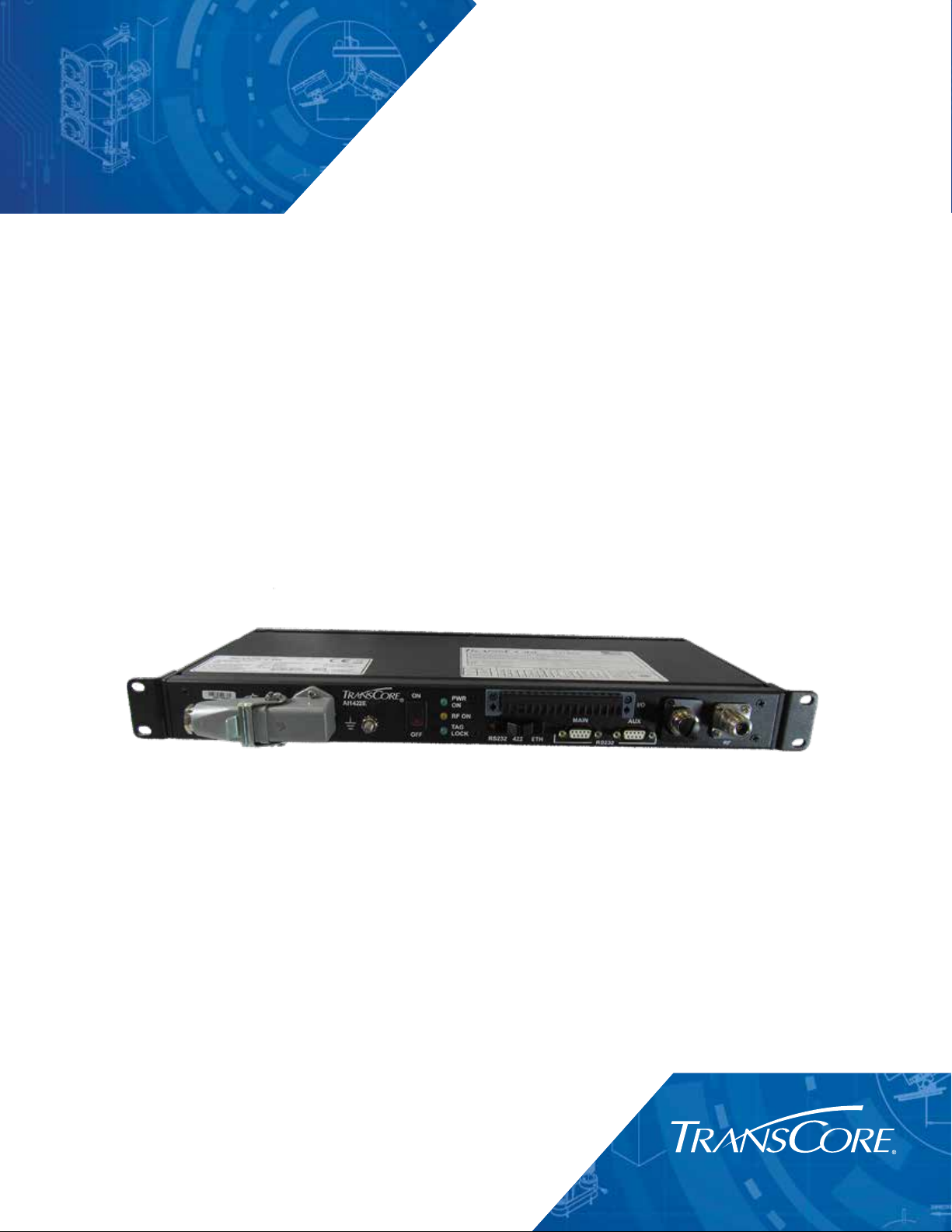
AI1422E Reader User Guide
LIMITES D’EXPOSITION AUX RADIOFRÉQUENCES POUR LE LECTEUR AI1422
UTILISANT UNE ANTENNE EXTERNE SUR LA BANDE
DE FRÉQUENCES DE 902.25 À 903.75 ET DE 910.00 À 921.50 MHZ
Plusieurs organismes (OSHA, FCC, IC) publient des directives environnementales qui recommandent
des limites d’exposition maximale autorisée (normes MPE) ou des niveaux d’exposition «sûrs»
auxquels cet appareil se conforme. Pour faire en sorte que chaque utilisateur final ait connaissance
des directives de sécurité qui le concerne, que ce soit dans son travail (accès contrôlé) ou pour
la population générale/le grand public (accès non contrôlé), TransCore présente les niveaux
recommandés par chaque organisme dans ses recommandations sécuritaires détaillées dans la
dernière section.
OSHA OCCUPATIONAL SAFETY AND HEALTH ADMINISTRATION
Dans le Code des réglementations fédérales (CFR), Titre 29, Partie 1910, Sous-partie G 1910.97,
intitulée «Nonionizing radiation» (Rayonnements non ionisants), l’OSHA (organisme américain)
recommande un plafond d’exposition maximale de 10 milliwatts par centimètre carré (mW/cm2)
pendant une période de 0,1 heure (soit 6 minutes). En utilisant la fréquence de 915 MHz (milieu de
la bande de fréquences de cet appareil) et le gain d’antenne maximal pour lequel cet appareil a
reçu une certification d’utilisation dans une installation finale, la distance minimale sécuritaire est de
20cm (8po).
FCC FEDERAL COMMUNICATION COMMISSION
Dans le Code des réglementations fédérales (CFR), Titre 47, Chapitre I, Sous-chapitre A, Partie 1,
Sous-partie I, Section 1.1310 intitulée «Radiofrequency radiation exposure limits» (Limites d’exposition
aux rayonnements de radiofréquence), la FCC (organisme américain) établit les limites d’exposition
maximale autorisée (normes MPE) comme suit :
Exposition professionnelle/contrôlée
Densité de puissance = fréquence (en MHz)/300 mW/cm2avec une durée moyenne de 6 min.
Exposition de la population générale/non contrôlée
Densité de puissance = fréquence (en MHz)/1500 mW/cm2avec une durée moyenne de 30 min.
En utilisant la fréquence de 915 MHz (milieu de la bande de fréquences de cet appareil) et le gain
d’antenne maximal pour lequel cet appareil a reçu une certification d’utilisation dans une installation
finale, la distance minimale sécuritaire est la suivante : les distances MPE minimales sont de 36cm
(14 po) pour l’environnement professionnel/contrôlé et de 80,5 cm (31,5 po) pour la population
générale/environnement non contrôlé.