TRANSIENT VIY5-125 User manual
VIY5-125
Ground Penetrating Radar
User Manual
Part 1. Equipment

© Transient Technologies LLC 2020
Transient Technologies LLC
ofce 604, 13 Evgena Sverstuka str.
Kyiv 02002, Ukraine
Phone: +380 (44) 240-85-94
E-mail: info@viy.ua
Web-site: www.viy.ua
VIY® – registered trademark of Transient Technologies LLC
All pictures in this User Manual are given for reference purpose only, and may differ from
actual product appearance.
Product design and specication may be changed by manufacturer without notication.

Contents
General information ................................................................................................. 4
VIY5-125. New generation of Ground Penetrating Radars............................................ 4
Application of VIY5-125 GPR.......................................................................................... 4
Package options ............................................................................................................... 4
VIY5-125m Manual version
Antenna + VO-36 odometer + transportation pole .......................................................... 4
List of Equipment and Accessories ................................................................................. 5
Main components description................................................................................. 6
VO-36 Measuring wheel (odometer) ............................................................................... 7
Transportation belt .......................................................................................................... 7
Backpack for GPR accessories and laptop shelf ............................................................ 7
Getting Started.......................................................................................................... 8
Manual version of VIY5-125 GPR .................................................................................... 8
Mounting Transportation pole and Odometer to antenna unit......................................... 8
Push-pull connectors....................................................................................................... 8
Connecting antenna unit to a laptop................................................................................ 10
Mounting the laptop shelf on the operator’s backpack ................................................ 11
GPR parameters setting and GPR calibration ............................................................... 13
GPR battery............................................................................................................... 14
Charging battery of VIY5-125 GPR................................................................................. 14
Battery replacement ........................................................................................................ 14
Specications ........................................................................................................... 16
Limited Warranty ...................................................................................................... 17

4
General information
General information
VIY5-125. New generation of Ground Penetrating Radars.
Ground Penetrating Radar (GPR) is designed for non-destructive scanning and inspecting of different
structures and underground objects.
GPR can be applied by geophysicists, building companies, can be used in different ecological investigations,
utilities condition assessment (including both metallic and non-metallic, plastic, concrete, asbestos pipes).
Also the equipment can be used for searching and mapping of: underground water sources leaks, oil and
other dangerous liquids underground pollutions; ground water level.
VIY5-125 Ground Penetrating Radar (GPR) has Dual Frequency antenna with central frequencies of 125
MHz.
Application of VIY5-125 GPR
• Utilities mapping and detection (pipes, cables);
• Civil engineering surveys (building basements, cellars etc.);
• Search for buried waste products, and graves;
• Mapping and location of near surface voids, karst and other cavities;
• Determination of boundaries of petroleum contamination zones etc.
• Forensic and security investigations.
Package options
Order information
VIY5-125 GPR can be ordered with three different options sets:
1. VIY5-125m Manual version
Antenna + VO-36 odometer + transportation pole
• 125 MHz antenna unit
• Odometer VO-36
• SH5-125 Replaceable bottom protector
• Transportation belt
• DC5-2 Cable (2.5m)
• Charger
• Backpack
• Laptop holder
• User manual
• User manual
9Laptop is not included in any GPR set and should be purchased separately
GPR
series
Manual version
with GPR pole
Central frequencies,
125 MHz
VIY5-125m

5
4
General information
General information
List of Equipment and Accessories
Item View Description
AB5-125 125 MHz frequency antenna unit with digital output, battery on
board. Built-in inclinometers.
Supports optional connection of GPS and measuring wheels.
Laptop holder Laptop holder, designed for fastening the laptop to the operator’s
backpack.
VO-36 VO-36 is a bidirectional odometer (measuring wheel) that measures
traveled distance in both directions. Odometer can be mounted to
an antenna unit and should be electrically connected to the antenna
by special connector.
Compatible with VIY5-125 GPR
SH5-300 Protective bottom cover SH5-300, compatible with AB5-37 antenna
unit.
Backpack The backpack for GPR antenna, accessories, laptop, and Battery
Box.
DC5-2 Cable Cable (2.5 m length) to connect DATA socket on the Handcart or
Battery Box to a laptop.
Charger Charger for lead acid batteries.
Included in all GPR sets.
GPS receiver External GPS receiver.
GPS kit includes:
• GPS receiver
• GPR cable
• GPR adapter (10cm)
Synchro3
Planner
Software package for VIY5 GPR sounding process control, and also
for processing and visualizing GPR data.
Full software set can be downloaded for free here:
http://viy.ua/download/install_VIY_SGPR.zip
6
Main components description
Main components description
GPR consists of antenna unit connected via USB to a computer (laptop). Operator controls antenna unit
through VIY5 software.
Optionally user can use with GPR antenna:
• GPS receiver
Manual version
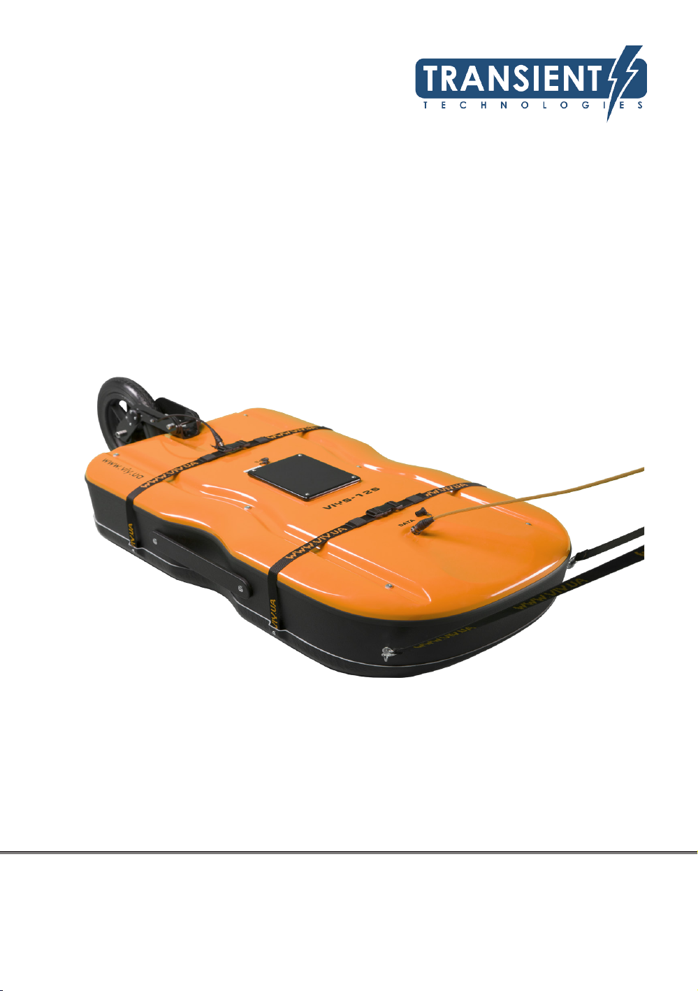
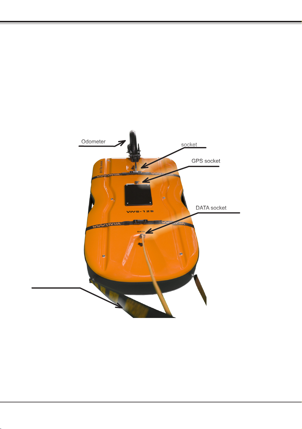
Picture below shows general view of the manual version of VIY5-125 GPR with VO-36 odometer and a
transportation belt.
Laptop can be placed on the laptop shelf that should be fastened to operator’s backpack.
DC5-2 Cable should be connected to DATA socket on the antenna and to USB port of operator’s laptop.
Odometer should be connected to Odometer socket on the antenna unit.
If GPS is present, it should be connected to GPS socket on the antenna unit.
Antenna unit with odometer and
transportation belt
Transportation belt
Odometer
socket
GPS socket
VO-36
Odometer
DATA socket

7
6
Main components description
Main components description
VO-36 Measuring wheel (odometer)
VO-36 is a bidirectional measuring wheel (odometer) that can be mounted on the antenna unit in manual
version of this GPR. It can be mounted to the antenna unit without any extra tools.
Transportation belt
The transportation belt is a special belt that should be xed to the antenna unit to move antenna during data
acquisition process.
Backpack for GPR accessories and laptop shelf
The backpack is included in each GPR set. The laptop shelf is an accessory that should be used as a
support for user’s laptop. The shelf can be fastened to the backpack.
The backpack contains compartments for:
• GPR accessories (cables, charger, transport belt etc.)
• Odometer VO-36
• User’s laptop
• Laptop shelf
Backpack with laptop
Laptop shelf
8
Getting Started
Getting Started
Manual version of VIY5-125 GPR
Mounting Transportation pole and Odometer to antenna unit.
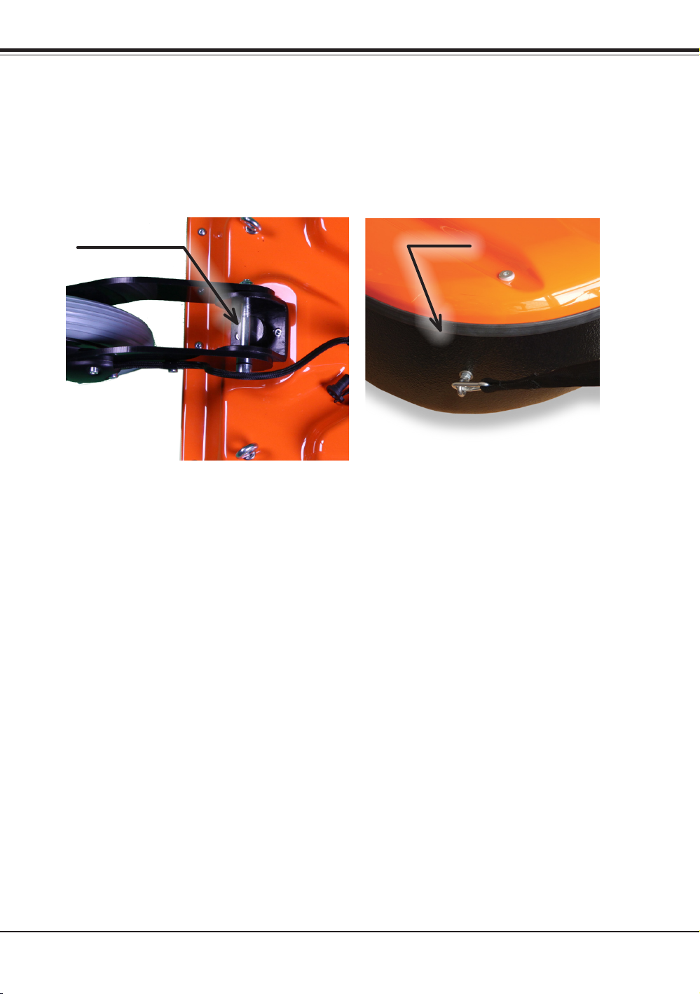
Mount odometer to the antenna unit and screw them manually. Connect the transportation belt to antenna
with carabiners. Connect the cable of odometer to antenna socket.
Odometer screw Carabiner
9
8
Getting Started
Getting Started
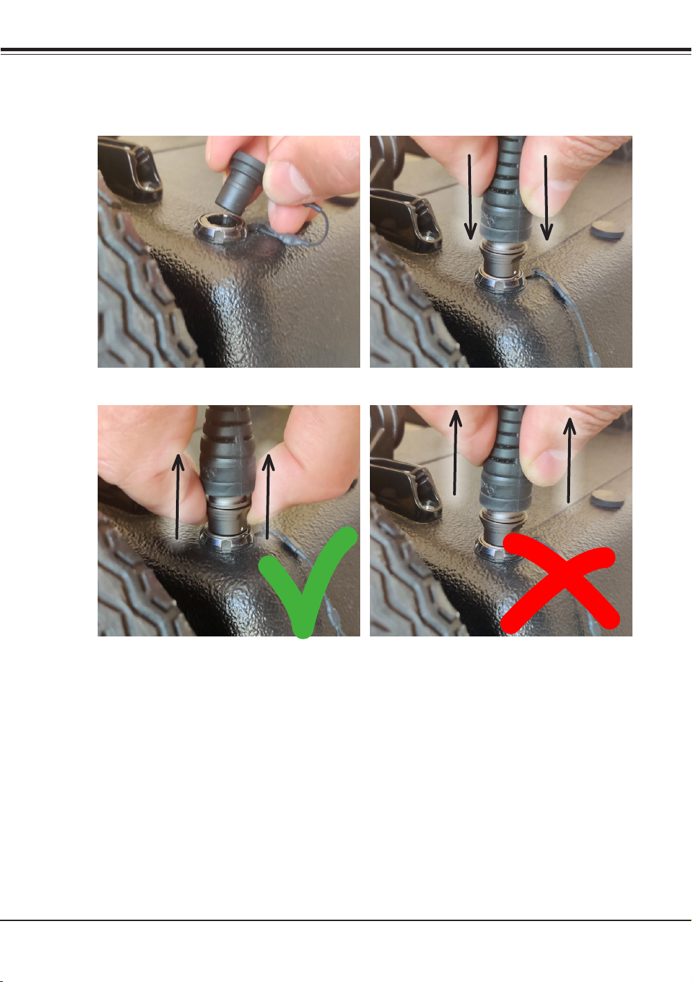
Push-pull connectors.
To connect push-pull connectors you should open cap then match together the white marks on a plug and a
socket correspondingly and then insert the plug by holding its housing.
To disconnect - just pull the plug ring back and disconnect it.
9GPR power supply is turning on when DATA socket is connected to the socket
9Do not pull the cable trying disconnect the plug. It may damage the connectors!

10
Getting Started
Connecting antenna unit to a laptop
Connect DC5-2 Cable (orange cable) to DATA socket on the antenna unit and to USB port of a laptop.

11
10
Getting Started
Getting Started
Mounting the laptop shelf on the operator’s backpack
If GPR is used together with VO-22 odometer, the laptop should be mounted on the special portable shelf
that should be fastened to the operator’s backpack.
To mount the laptop shelf follow the next steps:
• Take the laptop folder out of the backpack.
• Stick the Velcro tape on the top of Handcart shelf and on the laptop bottom in some places (the Velcro
tape is included in GPR set).
• Turn the shelf over and pull out the metallic holders (in direction shown by an arrow below).

12
Getting Started
• Turn the metallic holders 90 degree aside and put them into slots as shown on the picture below.
• Put the backpack on, adjust the backpack side stripes and fasten the backpack belt.
• Fasten operator’s shelf locks to the corresponding locks on the backpack stripes
• Tuck he lower holders of the shelf behind the operator’s backpack belt.
Slots

13
12
Getting Started
Getting Started
• Mount the laptop on the shelf, fastening it on the shelf with Velcro tape.
When the work is nished, fold the shelf in the back order and pack it to the backpack.
GPR parameters setting and GPR calibration
Please read User Manual part 2. Software to nd instructions about setting up all the main GPR
parameters, its calibration and directions of using Synchro and Planner software.
14
GPR battery
GPR battery
Each antenna unit is equipped with the sealed lead acid rechargeable battery (12 V, 7 Ah). The power supply
of the antenna unit prevents the deep discharge of the battery. The battery charge level is indicated in the
Status bar of the Main window of the Synchro3 software the battery.
When the battery voltage is low and close to the critical value, the power supply begins beeping. When the
battery voltage is below the cut-off threshold (10.8V) the power supply will turn the antenna unit off but beep
sound will continue ringing twice per second. That indicates the normal state of GPR and the necessity of
battery charging.
For battery charging use the charger that is included in GPR set.
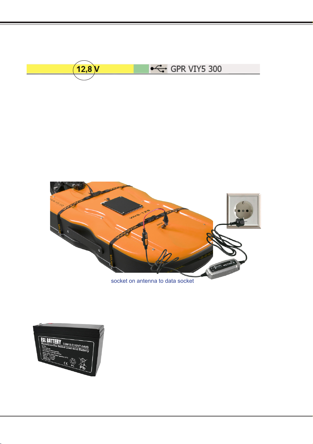
Charging battery of VIY5-125 GPR
For charging the battery of VIY5-125 GPR you should connect the charger plug into DATA socket that is
located on the Handcart (or into DATA socket on a Battery Box if connected), and then plug the charger to
the AC power (220-240V AC, 50-60 Hz).
Charging battery with antenna installed on the Handcart.
The battery is inside the battery compartment in the Handcart:
Charging battery with antenna outside of Handcart.
The battery is in the antenna:
9Connect adapter to the any socket on antenna to data socket
9To get more information please read the charger User manual that is in the charger set.
Battery replacement
All models of GPR use the same standard sealed lead acid rechargeable battery (12 V, 7 Ah).
9To get more information please read the charger User manual that is in the charger set.
To 220-240 AC
If you notice the Charger error light is on during the
charging process, it means that your battery must
be replaced for the new one.

15
14
GPR battery
GPR battery
Replace battery in Antenna Unit
To replace the battery in the Antenna Unit:
• Unscrew four screws on the Battery Box cover
• Use the tool from GPR set
• Take the cover off the battery compartment.
• Take the battery out
• Replace it respecting wires polarity
9Connecting the wires to battery, respect the polarity (red wire - battery positive pad,
blue – negative pad).
• Mount the Battery Box cover back on its place, x it with four screws.
Unscrew four screws

16
Specications
Specications
Model of GPR VIY5-125
Antenna unit, MHz 125
Max sounding depth, meters (depending on soil
properties)
15.0
Survey window, nsec 120, 180, 240, 300 nsec
Spatial resolution, meters, (not worse) <0.9 m
Maximum number of samples per trace 1000
Data acquisition rate, traces per second* up to 150
Dynamic range not less than 135 dB
Interface USB2
Trigger mode single, internal, external
Analogue-to-Digital Converter range 18 bit
Three-dimensional Inclinometer Built-in
Weight, kg 25
Dimensions, mm 1105x580x23
Operating temperature range -20°C to 40°C
Environmental rating IP65**
Continuous operation time not less than 8 hours
* Data acquisition rate depends on samples per trace and trace stacking.
** Optionally can be IP67
All antennas support external GPS that can be directly connected to antenna

17
Limited Warranty
Specications
Limited Warranty
1. Warranty.
Transient Technologies LLC warrants the enclosed hardware products to be free from defects in
material and workmanship for a period of 12 (twelve months) from the date of original retail purchase.
2. Repair Procedures, Exclusive Remedy.
Transient Technologies LLC will, at its option, repair or replace products not conforming to this limited
warranty at no charge. This is the sole and exclusive remedy available for breach of warranty or under
any other legal theory with respect to Transient Technologies LLC product. If you nd a product to
be defective, please contact your authorized Transient Technologies LLC representative or directly
to head ofce of Transient Technologies LLC. When you receive authorization, return the product as
directed, including proof of purchase and date, at your expense and risk. Product repairs not covered by
warranty, and product updates, will be provided at a set rate.
3. Limitations.
This warranty is to be avoided if the product is damaged by importer or abnormal use or by accident,
if the product is altered or modied in any way, or if any attempt is made to repair the product without
authorization from Transient Technologies LLC. It is solely the purchaser’s responsibility to determine
the suitability of these products for each particular application. Transient Technologies LLC products
are in all events not suitable, and are not authorized, for use with systems potentially injurious to life or
health. This warranty is not assignable.
4. No Other Warranties.
EXCEPT AS PROVIDED IN THIS LIMITED WARRANTY. TRANSIENT TECHNOLOGIES HARDWARE
is PROVIDED ‘AS IS’. ALL OTHER WARRANTIES AND REPRESENTATIONS, ORAL OR WRITTEN,
EXPRESS OR IMPLIED, INCLUDING BUT NOT LIMITED TO ANY IMPLIED WARRANTIES OF
MERCHANTABILITY OR FITNESS FOR A PARTICULAR PURPOSE, ARE EXCLUDED AND DO NOT
APPLY, THERE ARE NO WARRANTIES WICH EXTEND BEYOND THE DESCRIPTION OF THE FACE
HEREOF. Except as required by law, no representative, agent, or employee of Transient Technologies
LLC is authorized to make warranties, representations, or obligations inconsistent with or in addition
to those set forth in this limited warranty. TRANSIENT TECHNOLOGIES LLC DOES NOT WARRANT
FOR THE CONTENTS AND SERVICES OF OTHER SITES, WHICH YOU MAY ACCESS FROM
HYPERLINKS ON TRANSIENT TECHNOLOGIES LLC WEBSITES, TRANSIENT TECHNOLOGIES
LLC INSTALLATION CD OR ANY MATERIAL.
5. No Damages.
IN NO EVENT WILL TRANSIENT TECHNOLOGIES LLC BE LIABLE FOR DIRECT, INDIRECT,
SPECIAL, INCIDENTIAL, OR CONSEQUENTIAL, DAMAGES RESULTING FROM ANY BREACH OF
WARRANTY OR UNDER ANY OTHER THEORY, even if advised of the possibility of such damages.
In event Transient Technologies LLC be liable for sums in excess of the purchase price of the product.
Transient Technologies LLC is thus not liable for lost prots or goodwill; downtime; damage or
destruction of any program, data, equipment, or other property; cost of recovering, reprogramming, or
reproducing any program, data, or equipment; personal injury or loss; or any other damages.
6. General.
This agreement is the entire agreement between you and Transient Technologies LLC; supersedes
any prior or different agreements, representations, or proposals; and may be changed only by written
agreement with Transient Technologies LLC . Waiver by any default or breach of this agreement will not
constitute a waiver of any subsequent default or breach of the same or different kind. The invalidity of
any provision of this agreement shall not affect the validity of the other provisions hereof.
Table of contents
Other TRANSIENT Radar manuals


Popular Radar manuals by other brands

ZKTeco
ZKTeco VR10 Pro user manual

Northrop Grumman Sperry Marine
Northrop Grumman Sperry Marine VisionMaster FT user guide

Endress+Hauser
Endress+Hauser Micropilot S FMR540 Safety instructions

Kustom Signals
Kustom Signals Raptor RP-1 Operator's manual

MPH
MPH PYTHON III Operator's manual

Furuno
Furuno FAR-3210 installation manual

Endress+Hauser
Endress+Hauser Micropilot FMR62B PROFINET with Ethernet-APL technical information

Endress+Hauser
Endress+Hauser Levelflex FMP55 PROFIBUS PA Brief operating instructions

Decatur Electronics
Decatur Electronics Railmaster user manual

Axis
Axis D2110-VE installation guide

Kustom Signals
Kustom Signals Talon Radar Operator's manual

OmniPreSense
OmniPreSense OPS243-A user manual


