Transmille 8600 User manual

www. transmille.com
OPERATION MANUAL
TRANSMILLE 8600
FREQUENCY SOURCE /
MEASURE GPS STANDARD

Page 1
www.transmille.com
8600 Operation Manual - V1.0
TRANSMILLE 8600 OPERATION
MANUAL
FREQUENCY SOURCE / MEASURE GPS
STANDARD

Page 2
www.transmille.com
8600 Operation Manual - V1.0
Warranty
Transmille guarantees this product to be free from defects in material and workmanship under
normal user for a period of one (1) year from the date of shipment. This warranty does NOT cover any
required re-calibration/adjustment or standard maintenance actions. This warranty extends only to the
original end purchaser and does not apply to fuses, batteries, external cables or to the product if it has
been modified, misused, altered or has been subjected to mishandling or misuse.
Transmille’s obligation to warranty is limited to repair or replace the product after return to
an authorized Transmille service centre within the warranty period and is subject to Transmille’s
investigation determining that the fault is not caused by misuse, alteration or through mishandling.
If failure occurs, send the product via pre-paid freight, to the service centre as informed by
Transmille with a description of the fault only after receiving confirmation from Transmille. At
Transmille’s option, either repairs will be performed or a replacement unit of similar condition and
age will be provided.
Transmille will return the product to the end customer or local distributor via pre-paid freight
(with exception of any customs clearance fees).
Transmille accept no responsibility for damage during return shipping for warranty service.

Page 3
www.transmille.com
8600 Operation Manual - V1.0
Contents
General Specifications.............4
Declaration Of Conformity........5
8600 Frequency Source / Measure GPS Standard 6
Introduction........................................................6
Main Features....................................................6
Preparing the Unit for Use .......7
Initial Inspection.................................................7
Positioning the Standard....................................7
Positioning the Antenna......................................7
Rear Panel Connections ....................................8
Setting and checking the line voltage .................8
Powering up the Instrument................................9
RS232 Interface.................................................9
USB Interface.....................................................9
Ethernet Interface ..............................................10
GPIB Interface ...................................................10
Front Panel Connections .........11
Output Connectors.............................................11
Input Connectors................................................11
Input Characteristics ..........................................11
Operation ................................12
Front Panel Controls..........................................12
Main Display ......................................................12
Status Display....................................................13
Entering Values..................................................13
GPS Status..............................13
GPS Strength.....................................................13
Time Display ......................................................13
Location.............................................................14
Output Functions.....................14
10 MHz Reference Frequency............................14
Low Frequency Divided Output ..........................15
Low Frequency Variable Output - Square Wave..15
Low Frequency Variable Output - Variable Sine..16
High Frequency Variable Output.........................17
A → B Phase Reference Output .........................17
Input Functions........................18
Gate Settings.....................................................18
Trigger Level......................................................18
Sensitivity ..........................................................18
High Frequency Filter.........................................18
AC / DC Coupling...............................................19
Low Frequency Measurement ............................19
Period Measurement..........................................20
High Frequency Measurement............................20
Remote Commands.................21
Introduction........................................................21
Programming Overview......................................21
Compound Commands.......................................21
Response / Error Codes.....................................22
Frequency Source - 10 MHz Output ...................22
Frequency Source - 1Hz - 5MHz Divided Output 22
Frequency Source - Low Frequency 5V Pk-pk....23
Frequency Source - Low Frequency Sine...........24
Frequency Source - High Frequency..................25
Frequency Source - A-B Relative Phase.............26
Frequency Measurement - Gate Time.................27
Frequency Measurement - Trigger Level ............27
Frequency Measurement - Sensitivity.................27
Frequency Measurement - High Frequency Filter 28
Frequency Measurement - AC / DC Coupling .....28
Frequency Measurement - Low Frequency Input 29
Frequency Measurement - High Frequency Input 29
Frequency Measurement - Period ......................30
Query Current Function......................................30
Query GPS Status..............................................31
Query Number of Satellites ...............................31
Query Latitude and Longitude ............................31
Query Date ........................................................31
Query Time ........................................................32
Theory of Operation.................33
Circuit Description..............................................33
Traceability ........................................................33
Page 4
www.transmille.com
8600 Operation Manual - V1.0
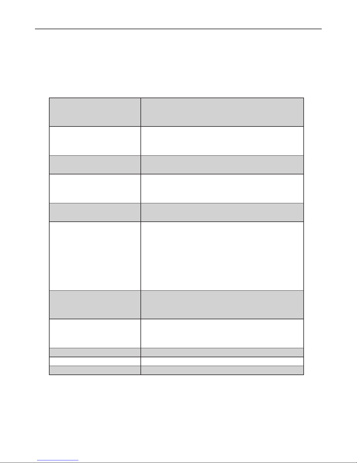
General Specications
Temperature
Performance
Storage : -5℃ to + 60℃
Operation : 0℃ to +50℃
Humidity Performance Storage : <95%, non-condensing
Operation : <80% to 30℃, <70% to 40℃, <40%
to 60℃
Altitude Storage / Transit : 12,000m (40,000ft) Maximum
Operation : 3000m (10,000ft) Maximum
Dimensions Width : 45cm / 17.7 in
Length : 44cm / 17.3 in
Height : 10cm / 3.9 in
Weight 8.5 kg
18.8 lbs
Connectors Front Panel : 5 x BNC
Rear Panel : 3 x BNC
1 x USB Receptacle
1 x GPIB Connector
1 x Female RS232
1 x RJ45 Socket
1 x IEC Mains Inlet
Line Power Line Voltage Selectable : 110V / 230V
Line Frequency : 50 to 60Hz
Line Voltage Variation : -6% + 10%
Display Information Type : VFD
Number of Lines (Main Display ) : 1
Number of Lines (Secondary Display) : 2
Keyboard Rubber Key
Fuses Mains Inlet : 500 mA
Warranty Period 1 Year

Page 5
www.transmille.com
8600 Operation Manual - V1.0
DECLARATION OF CONFORMITY
Manufacturer’s Name: Transmille Ltd.
Manufacturer’s Address: Unit 4, Select Business Centre
Lodge Road
Staplehurst
TN12 0QW
Declares, that the product
Product Name: Frequency Source / Measure GPS Standard
Model Number: 8600
Product Options: This declaration covers all options of the above product(s)
Conforms with the following European Directives:
The product herewith complies with the requirements of the Low Voltage Directive 73/73EEC
and the EMC Directive 89/336/EEC (including 93/68/EEC) and carries the CE Marking accordingly
Conforms with the following product standards:
EMC
EN 61326-1:1997+A1:1998 • EN55011:1991 (Group 1 : Class A)
Standard Limit
IEC 61000-4-2:1995+A1:1998 / EN 61000-4-2:1995 4kV CD, 8kV AD
IEC 61000-4-3:1995 / EN 61000-4-3:1995 3 V/m, 80-1000 MHz
IEC 61000-4-4:1995 / EN 61000-4-4:1995 0.5kV signal lines, 1kV power lines
IEC 61000-4-5:1995 / EN 61000-4-5:1995 0.5kV line-line, 1kV line-ground
IEC 61000-4-6:1996 / EN 61000-4-6:1996 3V, 0.15-80 MHz / cycle, 100%
IEC 61000-4-11:1994 / EN 61000-4-11:1994 Dips: 30% 10ms; 60% 100ms
Interrupt > 95%@5000ms
Date : 02/03/2015
Revision No: 1.00 Director
Declaration Of Conformity

Page 6
www.transmille.com
8600 Operation Manual - V1.0
8600 Frequency Source / Measure GPS Standard
Introduction
The 8600 Frequency Source / Measure GPS Standard has been designed to able to calibrate
all functions of modern hand held and bench frequency counters and signal sources. A high accuracy
precision GPS reference frequency of up to 1 GHz is available, with outputs for A-B phase and
variable levels for confirming trigger levels of modern counter-timer units
In addition, unlike other GPS references, the 8600 also adds the ability to measure frequencies
of up to 1 GHz with high precision, removing the requirement for an additional instrument in your
laboratory. Utilising the latest in GPS reference technology, the 8600 combines both frequency source
and measurement into a single integrated solution.
Dual VFD displays provide the user with a dedicated source/measure readout, with direct
access to detailed settings and satellite Lock/signal information.
Main Features
• Precision 10MHz output synchronised to GPS reference enabling traceable frequency output anywhere
in the world with no requirement for external calibration.
• Digitally divided frequency output from 1 Hz to 5 MHz in 1,2,5 steps internally disciplined to GPS
referenced 10 MHz.
• 5V peak-peak square wave frequency output from 10 Hz to 2 MHz.
• Variable level sinewave output into 1 MΩ (1mV to 5V) or 50Ω (1mV to 2.5V) from 10Hz to 2MHz.
• High Frequency output from 10 MHz to 1.05 GHz internally disciplined to GPS.
• Frequency measurement from 1 Hz to 1 GHz, internally disciplined to GPS.
• A-B output for verifying phase meters with output from 0° to 359° at frequencies from 1 Hz to 50 kHz.
• Dual VFD Screens ensure clear display of measurements, outputs and menu functions.

Page 7
www.transmille.com
8600 Operation Manual - V1.0
Preparing the Unit for Use
Initial Inspection
After shipment the standard should be inspected for any signs of external damage. Should
external damage be found contact the carrier immediately. Do not connect a damaged instrument to
the line power as this may result in internal damage. Please retain the original packaging; this should
be used when returning the standard for service.
Ensure that all external calibration seals are intact and show no sign of tampering.
Positioning the Standard
The standard should be placed where access to both front and rear connections is not hampered.
Transmille advise that at least 5cm clearance is allowed to the rear to allow the passing of power
cables to the input is allowed.
Positioning the Antenna
To operate correctly the 8600 requires a GPS antenna with full view of the sky to achieve a
stable lock with GPS satellites.
A range of antennas with varying cable lengths are available for purchase from Transmille with
magnetic backing to affixing to the exterior of buildings.
Although it may be possible to receive GPS lock with the antenna mounted internally (for
example near a window) Transmille would advise that the antenna is fixed permanently outside to
ensure a stable lock, especially in built up areas.

Page 8
www.transmille.com
8600 Operation Manual - V1.0
Rear Panel Connections
Connections are offered on the rear panel of the 8600 as below
On the rear USB, RS232, RJ45 and GPIB connectors can be used for controlling the instrument
remotely. A BNC connector is provided for the GPS antenna input (labelled), 1PPS output and
dedicated 10 MHz out.
If specified, an option to have 6 additional buffered 10 MHz outputs will be provided each with
independant BNC connectors
Due care should be taken to prevent damage to the internal pins of the BNC connectors by
using only undamaged male BNC cables to connect.
Setting and checking the line voltage
The standard has been designed to work from either 110-120V or 220-240V line supply. The
user should confirm that the correct voltage has been set prior to connecting power to the instrument.
Connecting the instrument to the wrong power supply could cause damage to the instrument. To
change the line voltage, remove the fuse / voltage selector housing from the rear of the unit, rotate
through 180° and replace with he required voltage setting at the bottom of the housing.
The instrument is set for 110V operation when shipped to the USA, for all other regions the
instrument is shipped set to 230V operation.
Page 9
www.transmille.com
8600 Operation Manual - V1.0
Powering up the Instrument
After connecting line power, the instrument can be switched on with the power switch on the
rear of the instrument.
The front panel display will illuminate and the instrument will begin its start up sequence. This
process takes approximately 15 seconds. After powering on, allow the unit to acquire a GPS fix, as
identified on the front panel prior to use.Connecting to a computer
The 8600 is fitted with USB, RS232, GPIB and Ethernet interfaces for connecting to a
computer. For best compatibility with ProCal, Transmille advise that the USB connection is used.
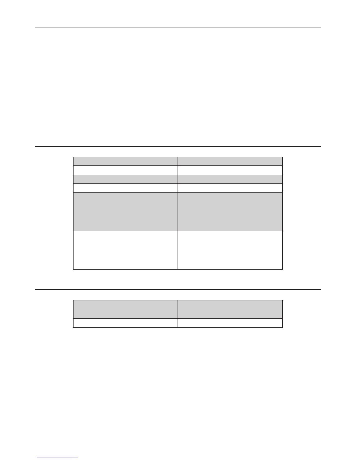
RS232 Interface
Baud Rate 9600
Parity None
Data Bits 8
Stop Bits 1
Cable Type
Male to Female Serial Cable
(9 pin D Type)
Straight through pin
connection (NOT Null Modem)
Software Driver
N/A - If used with
Transmille USB to RS232 adapter
FTDI drivers as provided should be
installed
USB Interface
Cable Type USB ‘A’ Type connector to
USB ‘B’ Connector
Software Driver FTDI USB Driver (supplied)

Page 10
www.transmille.com
8600 Operation Manual - V1.0
Ethernet Interface
Configuration Via optional configuration utility for
computer
Cable Type 100Bast T Ethernet Cable (RJ45)
Software Driver N/A
GPIB Interface
Configuration
Press MENU until GPIB Address : is
displayed
Enter new GPIB Address (Valid
range 0-30)
Press ENTER
Cable Type GPIB Interface Cable
Software Driver National Instruments VISA or
equivalent

Page 11
www.transmille.com
8600 Operation Manual - V1.0
Front Panel Connections
The 8600 features 5 BNC connectors on the front panel for simple connections to frequency
counters and sources. 3 of the BNC connections are used for OUTPUT, 2 of the connectors are used
for INPUT.
Output Connectors
Output connectors are provided for Low Frequency (up to 10 MHz) outputs A and B, and a
dedicated output for the High Frequency (up to 1.05 GHz) output.
Only the active function will have an output present at the terminal, other terminals are
disconnected while not in use.
Low Frequency output A is used for the primary 10 MHz output, Frequency Divider(1,2,5
sequence) and Variable level outputs(5V Square and Variable Sine Wave)
Low Frequency output B is only active when in Phase Offset mode.
Input Connectors
Input connectors are provided for both low frequency input (up to 10 MHz) and high frequency
input (up to 1.05 GHz) via two BNC inputs.
Input Characteristics
The Low Frequency input has an input impedance of 1 MOhm, an input capacitance of 25pF
and has a maximum input of 20V
The High Frequency input has an input impedance of 50 Ohms, with a maximum input of 1V

Page 12
www.transmille.com
8600 Operation Manual - V1.0
Operation
Front Panel Controls
For ease of use, the front panel keyboard is separated into 3 sections. The first is OUTPUT
functions and configuration, the second is MEASUREMENT functions and configuration, and then a
general purpose keyboard for navigation and numerical entry.
The function of each key is described in detail throughout the operation manual. In
summary, the block of 8 buttons on the left of the keyboard select FUNCTIONS, the center keys set
CONFIGURATION or MENU functions and the right hand keys are for numerical entry.
The TOP row of keys in the left hand section control SOURCE functions, the BOTTOM row of
keys in the left hand section control MEASURE functions
To assist the operator, the currently active function is highlighted in GREEN to provide
immediate feedback at a glance.
Main Display
The main display of the 8600 is a bright single line VFD for enhanced readability. This screen
displays either the current OUTPUT or the current MEASUREMENT depending upon the mode.
At the end of the screen there is an indicator to display the current state of the GPS Reference.
If “Int” is displayed this indicates that no fix has been achieved to the GPS system. This is normal for
the first 10 - 20 minutes after installation, however should not appear during normal use.
If “GPS” is displayed at the end of the screen this indicates that a good fix has been achieved
and the 10 MHz reference is currently being disciplined to the GPS system

Page 13
www.transmille.com
8600 Operation Manual - V1.0
Status Display
The smaller status display is used to indicate the function, current status of user configurable
parameters as well as menu functions.
The status display is split across 2 lines. In entry mode the bottom line shows the value that is
being entered
Entering Values
Using the numerical section of the keyboard users can enter parameters for output /
configuration directly into the unit.
After the desired function has been selected, use the numerical keyboard to enter the desired
value. Appropriate units are automatically added.
To enter a multiplier, press the SHIFT key and then press the key with the appropriate
multiplier above the key, for example for kHz press the SHIFT key, followed by 1
Clear, Backspace and decimal place keys have also been included as SHIFT functions.
GPS Status
GPS Strength
To view the current GPS Signal strength and number of satellites currently locked, press the
MENU key once. The following screen will be displayed on the status screen.
Time Display
Pressing the MENU key again will display the current date and time to UTC standards.

Page 14
www.transmille.com
8600 Operation Manual - V1.0
Location
Pressing the MENU key once more will display the current location in the following format :
Latitude: DD°mm.mmm H
Longitude : DDD°mm.mmm H
Where D denotes degrees, m denotes minutes and H is the hemisphere (North, South / East,
West)
Output Functions
10 MHz Reference Frequency
The default start up state for the 8600 is for the 10 MHz reference frequency signal to
be present on the Low Frequency (LF) A terminal. The status display will indicate GPS 10MHz
Reference
This output is disciplined to GPS and requires no calibration to maintain specifications as long
as a GPS lock is achieved.
In this mode the Main Display will indicate 10 MHz, followed by either “Int” or “GPS”. A
display of “GPS” indicates that the unit is currently disciplined to GPS, a display of “Int” means that a
fix has not been achieved.

Page 15
www.transmille.com
8600 Operation Manual - V1.0
Low Frequency Divided Output
Pressing the 1 Hz - 10 MHz key when the unit is in 10MHz Frequency Mode will set the 8600
to Frequency Divider Output Mode. In this mode the output frequency can be varied in steps of 1, 2,
5 from 1 MHz to 5 MHz.
In this mode the Main Display will indicate the current output frequency, followed by either
“Int” or “GPS”. A display of “GPS” indicates that the unit is currently disciplined to GPS, a display of
“Int” means that a fix has not been achieved.
The output is varied using the digital control, rotating clockwise to INCREASE the frequency,
and anti-clockwise to DECREASE the frequency.
Direct digit entry is also possible using the numerical section of the keyboard, followed by
pressing the ENTER key. Entries which are not valid will select the next available frequency (i.e. an
entry of 300 Hz will select the 500 Hz output.
The output for this function appears at the LF Source A Terminal
Low Frequency Variable Output - Square Wave
Pressing the LF Mode key will set the unit to DDS Square Wave Output Mode. In this mode
the frequency can be varied from 10 Hz to 100 kHz in 1 Hz steps. The output is a fixed square wave
with a peak to peak amplitude of 5V into 1 MOhm.
In this mode the Main Display will indicate the current output frequency, followed by either
“Int” or “GPS”. A display of “GPS” indicates that the unit is currently disciplined to GPS, a display
of “Int” means that a fix has not been achieved. The smaller status display will indicate DDS Square
Wave 5V Pk-pk Output Mode
The output is varied using the digital control, rotating clockwise to INCREASE the frequency,
and anti-clockwise to DECREASE the frequency.
Direct digit entry is also possible using the numerical section of the keyboard, followed by
pressing the ENTER key.
The output for this function appears at the LF Source A Terminal

Page 16
www.transmille.com
8600 Operation Manual - V1.0
Low Frequency Variable Output - Variable Sine
Pressing the LF Mode key again will set the unit to DDS Sine Wave Output Mode. In this
mode the frequency can be varied from 10 Hz to 2 MHz in 1 Hz steps. The output is a variable level
sine wave that can be configured for output into either a 1 MOhm input impedance or a 50 Ohm input
impedance.
In this mode the Main Display will indicate the current output frequency, followed by
either “Int” or “GPS”. A display of “GPS” indicates that the unit is currently disciplined to GPS, a
display of “Int” means that a fix has not been achieved. The smaller status display will indicate DDS
Variable Sine and the currently configured output impedance.
The output is varied using the digital control, rotating clockwise to INCREASE the frequency,
and anti-clockwise to DECREASE the frequency.
Direct digit entry is also possible using the numerical section of the keyboard, followed by
pressing the ENTER key.
To vary the level, press the LEVEL key and then observe the current output on the smaller
screen. The default in both output impedance modes is 1V. The output voltage is displayed as the RMS
level. The output can be varied either with the digital control or through direct numerical entry.
Note : Outputs below 0.26V will be displayed in mV, outputs above will be displayed in V.
To change the output impedance, press the SHIFT key followed by the LEVEL key. The status
display will update to indicate either Hi Impd Output or 50Ω Impd Output.
The output for this function appears at the LF Source A Terminal

Page 17
www.transmille.com
8600 Operation Manual - V1.0
High Frequency Variable Output
Pressing the LF Mode key again will set the unit to High Frequency VCO Output Mode. In
this mode the frequency can be varied from 5 MHz to 1.05 GHz in 1 Hz steps. The output is a variable
level sine wave.
In this mode the Main Display will indicate the current output frequency, followed by
either “Int” or “GPS”. A display of “GPS” indicates that the unit is currently disciplined to GPS, a
display of “Int” means that a fix has not been achieved. The smaller status display will indicate High
Frequency VCO Output Mode.
The output is varied using the digital control, rotating clockwise to INCREASE the frequency,
and anti-clockwise to DECREASE the frequency.
Direct digit entry is also possible using the numerical section of the keyboard, followed by
pressing the ENTER key.
To adjust the level, press the LEVEL key and then adjust the level from 0 to 100%. The level
can be adjusted via the digital control or via direct keyboard entry.
The output for this function appears at the HF Source Terminal
A → B Phase Reference Output
Pressing the A→B Ref key will set the unit to Phase Offset Mode. In this mode a phase error
is generated between LF Output A and LF Output B to verify phase measurement functions of timer
counter instruments.
In this mode the Main Display will indicate the current output frequency, followed by either
“Int” or “GPS”. A display of “GPS” indicates that the unit is currently disciplined to GPS, a display
of “Int” means that a fix has not been achieved. The smaller status display will indicate A→B Phase
Output and the current phase error between the two outputs on the second line.
The output frequency can be varied by setting the unit to the Low Frequency Divided output
mode, and then re-selecting A→B Phase Reference Output mode again.
The output is varied using the digital control, rotating clockwise to INCREASE the
phase error and anti-clockwise to DECREASE the phase error.
Direct digit entry is also possible using the numerical section of the keyboard, followed by
pressing the ENTER key.

Page 18
www.transmille.com
8600 Operation Manual - V1.0
Input Functions
In addition to the source functions, the 8600 combines a high resolution frequency counter
that is internally disciplined to GPS reducing the requirement for separate pieces of equipment and
complicated wiring and interconnections.
Gate Settings
The measurement gate allows the user to select the duration of the measurement. Higher gate
times provide more resolution, however measurements will be slower to react to changes in frequency.
The gate time is selectable from 0.1, 1 and 10 seconds by pressing the DIGITS key on the front
panel.
Trigger Level
The trigger level sets a minimum input level at which the counter starts a measurement. For
measurements where there is the potential for distortion setting the trigger level can ensure that only
the peaks are captured and any incorrect counts caused by distortion on the waveform are ignored.
The trigger level is set by pressing the TRIGGER LEVEL key and then adjusting via the digital
control until a stable trigger is achieved.
Sensitivity
The sensitivity mode sets the hysteresis level around the trigger level. When in high sensitivity
mode the hysteresis around the trigger point is widened to enable the counter to trigger off of a wider
range of levels. When in low sensitivity mode the hysteresis around the trigger point is narrowed to
reduce the possibility of false triggering when distorted signals are being measured.
The sensitivity is set between HIGH and LOW by pressing the SENSE HIGH-LOW key. The
current sensitivity is displayed in the status display.
High Frequency Filter
The High Frequency filter assists with noise when measuring frequencies below 400 Hz by
placing a passive low pass filter in the internal signal chain to prevent high frequencies triggering the
counter.
To enable or disable the High Frequency filter press the HF FILTER key. The current filter
state is displayed in the status display as Flt Off or Flt on depending on the present status of the filter.

Page 19
www.transmille.com
8600 Operation Manual - V1.0
AC / DC Coupling
The AC / DC coupling setting enables the removal of the signals DC content (in AC Coupling
mode).
AC Coupling helps to measure high frequency measurements by filtering any DC components
and removing them from the measurement.
Note : Low frequency signals may be filtered if AC coupling is enabled. It is recommended
that the DC Coupled mode is used in conjunction with the High Frequency filter when measuring low
frequency signals.
To switch between AC and DC coupled modes, press the AC/DC COUPLED key. The current
state is displayed in the status display as AC for AC coupled, and DC for DC coupled.
Low Frequency Measurement
Pressing the LF Range key will set the unit to Low Frequency Measurement Mode. In this
mode the instrument measures the frequency of the signal connected to the LF Measure Input. The
maximum input frequency is 10 MHz, and the maximum input is 20 V. The input impedance of this
input is 1 Mohm with a capacitive loading of 25pF
In this mode the Main Display will indicate the current measurement, followed by either “Int”
or “GPS”. A display of “GPS” indicates that the unit is currently disciplined to GPS, a display of “Int”
means that a fix has not been achieved. The smaller status display shows the Gate setting, Trigger
level, Sensitivity, HF Filter state and the current coupling mode.
To set measurement parameters, refer to the previous sections which detail each setting.
Table of contents
Other Transmille Measuring Instrument manuals

Popular Measuring Instrument manuals by other brands


SEP
SEP LEM012SJ user manual

Vortex
Vortex RWG Series user manual

Honeywell
Honeywell QA 10 DN 25 G I instruction manual

Precision Digital Corporation
Precision Digital Corporation Helios PD2-6363 instruction manual

BRONKHORST
BRONKHORST MASS-STREAM D-6200 instruction manual

ALL-TEST PRO
ALL-TEST PRO ATPOL II user manual


