ALL-TEST PRO ATPOL II User manual

1
ALL-TEST PRO, Inc.
PO Box 1139, Old Saybrook,
CT 06745
Tel: 860-399-4222
Fax: 860-399-3180
www.alltestpro.com
Rev for FW 5.3f / SW 3.4F
© 2013 by ALL-TEST Pro, LLC All Rights Reserved
ATPOL II is a registered trademark of ALL-TEST Pro, LLC.
User’s Manual
for
ATPOL II
For Power Quality Operation
TM
For Motor Testing use the
manual named:
ESA 6 User Manual

2
The APOL II is designed to comply with part 15, subpart B, of the FCC Rules for a Class A digital
device.
Model ATPOL II is designed to comply with the requirements of IEC61010-1:2001 for a 600V input
rating measurement category IV, pollution degree II, double insulated electronic device.
Model ATPOL II is manufactured for ALL-TEST Pro, LLC in the U.S.A. The standard warranty period is
12 months from date of purchase unless you have purchased an extended warranty. We encourage
you to advise us of any defects of design or manufacture of any of our products. We are dedicated to
your successful use of the product.
There are no user serviceable parts in your ATPOL II meter. Opening the case voids your
warranty and may result in present or future danger to users of the meter. The rechargeable battery
inside is a custom-designed battery pack that is only to be replaced by authorized ALL-TEST Pro, LLC
(ATP) technical service personnel.
Cleaning is to be done by use of a dry or damp piece of cloth. Grease may be removed by light
application of isopropyl (rubbing) alcohol. Avoid the use of solvents, since they may dissolve or
weaken the plastic enclosure. Do not use water or other conductive liquids since they may pose a
safety risk.
Use of this equipment in a manner not specified by ATP can result in injury and voiding of
warranty.

3
Table of Contents
Introducing ATPOL II..................................................................7
Connecting to ATPOL II..............................................................7
Voltage Test Leads....................................................................................... 7
Current Probes.............................................................................................. 8
Connections to ATPOL II............................................................................. 9
Introduction to Power Delivery Configurations........................................ 11
Connecting to Single-phase Power.......................................................... 12
Connecting to 120 V Outlet Adapter Box................................................. 12
Connecting to Multiple Single-phase Loads............................................ 13
Connecting to Split-Phase (Two Phase) Power ..................................... 13
Connecting to Three-Phase Four-Wire (Wye) Power............................ 13
Connecting to Three-Phase Three-Wire (Delta) Power ........................ 14
Connecting to Three-Phase Four-Wire Delta Power............................. 14
Connecting to Three-Phase Grounded Delta Power............................. 14
Connections Using 2 Current Approach.................................................. 15
Connections To a 3 CT / 3 PT Metering Circuit...................................... 15
Connections To a 2 CT / 2 PT Metering Circuit...................................... 16
Connections To an Open Delta (3CT / 2PT) Metering Circuit.............. 16
Connecting to Line-To-DC (LDC) Converter Accessory ....................... 17
Measuring Multiple Parallel Conductors.................................................. 18
Measuring Currents Below the Range of the Current Probe................ 19
Turning ATPOL II On ................................................................20
Connecting to Power .................................................................................. 20
Turning ATPOL II On.................................................................................. 20
Turning ATPOL II Off.................................................................................. 20
Communicating with ATPOL II.................................................21
Introduction .................................................................................................. 21
Step 1: Connecting to the Meter at the Operating System Level......... 21
Step 2: Connecting to the Meter in PSM (the Application Level)......... 22
Using Removable Memory Cards............................................23
Introduction .................................................................................................. 23
Operation and Limitations.......................................................................... 23
Using the Memory Card Data with PSM.................................................. 24
Verifying Connections Using ATPOL II (SureStartTM).............25
Importance of Verifying Connections and Wiring................................... 25
Identifying the Power System.................................................................... 26
Error Summary............................................................................................ 26
Identifying Errors......................................................................................... 27
Checking out Connections using PSM....................................29
Checking Voltage Levels –Using PSM................................................... 29
Check Voltage Phase Sequence –Using PSM...................................... 30
Checking Current Levels –Using PSM ................................................... 30
Checking I Phase Sequence –Using PSM............................................. 30
Checking Phase Lag Angle –Using PSM............................................... 31

4
Measurement Types .................................................................32
Voltage Measurements .............................................................................. 32
Voltage Measurements in ATPOL II......................................................... 33
Voltage Measurements in PSM ................................................................ 34
Current Measurements ............................................................................. 35
Current Measurements in ATPOL II......................................................... 36
Current Measurements in PSM................................................................. 36
Imbalance Measurements ......................................................................... 37
Imbalance Measurements in PSM............................................................ 38
Power Measurements................................................................................. 38
Power Measurements in ATPOL II........................................................... 39
Power Measurements in PSM................................................................... 39
Power Factor Measurements.................................................................... 40
True Power Factor Measurements in ATPOL II ..................................... 41
Displacement P.F. and Phase Measurements in ATPOL II.................. 42
Power Factor and Phase Measurements in PSM.................................. 43
Energy Measurements............................................................................... 43
Energy Measurements in ATPOL II.......................................................... 44
Energy Measurements in PSM ................................................................. 44
Cost Measurements.................................................................................... 45
Cost Measurements in ATPOL II.............................................................. 45
Cost Measurements in PSM...................................................................... 46
Demand Period Measurements................................................................ 46
Demand Period Measurements in ATPOL II........................................... 46
Demand Period Measurements in PSM .................................................. 47
Frequency Measurements......................................................................... 47
Frequency Measurements in ATPOL II ................................................... 47
Frequency Measurements in PSM........................................................... 48
Duty Cycle / Power Cycle Measurements............................................... 48
Duty Cycle / Power Cycle Measurements in ATPOL II ......................... 49
Time and Capacity Measurements........................................................... 49
Time and Capacity Measurements in ATPOL II..................................... 50
Time and Capacity Measurements in PSM............................................. 51
Harmonic Measurements........................................................................... 51
Harmonic Measurements in ATPOL II..................................................... 52
Harmonic Measurements in PSM............................................................. 53
Swells (Surges) and Inrush Measurements............................................ 53
Dips (Sags) Measurement......................................................................... 53
High-Speed Transient Measurements..................................................... 54
Measurement Modes ................................................................55
Introducing Measurement Modes............................................................. 55
Phase-Neutral vs Phase-Phase vs 2 Current Mode.............................. 55
Changing the Voltage Measurement Mode in ATPOL II....................... 56
Changing the Voltage Measurement Mode in PSM............................... 56
50/60/400Hz vs DC vs Variable Frequency............................................ 57
Changing the Frequency Measurement Mode in ATPOL II.................. 58
Changing the Frequency Measurement Mode in PSM ......................... 58
Always Positive Power versus Negative Power Allowed ...................... 58
Changing the Power Measurement Mode in ATPOL II......................... 59
Changing the Power Measurement Mode in PSM................................. 59
Defining Inputs............................................................................................. 59
Changing Input Ratios in ATPOL II .......................................................... 60
Changing Input Ratios in PSM.................................................................. 60

5
Voltage & Current Waveforms .................................................62
Introduction .................................................................................................. 62
Saving Consumption Waveforms ............................................................. 62
Receiving Stored Consumption Waveforms ........................................... 63
Viewing Consumption Waveforms............................................................ 64
Monitoring Power Consumption..............................................67
Introduction .................................................................................................. 67
Basic Consumption Data Logging............................................................ 68
Receiving Consumption Data Log from ATPOL II.................................. 69
Viewing Consumption Logs....................................................................... 70
Custom Consumption Data Logging.......................................71
Introduction .................................................................................................. 71
Starting Data Logging................................................................................. 71
Stopping Data Logging............................................................................... 71
Setting the Consumption Logging Period................................................ 72
Setting Measurement Types ..................................................................... 72
Setting Measurement Modes .................................................................... 74
Saving and Retrieving Data Setups to File or ATPOL II in PSM ......... 74
Loading Data Setups from the Memory Card (SD Card) ...................... 74
Saving Data Setups to the Memory Card (SD Card)............................. 74
Restoring the Default Setup ...................................................................... 75
Monitoring Swell/Dip/Inrush.....................................................75
Introduction .................................................................................................. 75
Swell/Dip Event Log.................................................................................... 76
Swell/Dip RMS Graph Log......................................................................... 77
Swell/Dip Event Waveforms...................................................................... 78
Setting the Swell/Dip Trigger Thresholds in ATPOL II........................... 78
Setting the Swell/Dip Trigger Thresholds in PSM.................................. 79
Receiving Swell/Dip Data from ATPOL II................................................ 80
Viewing Swell/Dip Event Data................................................................... 80
Monitoring High-Speed Transient Events...............................81
Introduction .................................................................................................. 81
Transient Event Log.................................................................................... 82
Transient Event Waveforms...................................................................... 82
Setting the Transient Trigger Thresholds in ATPOL II........................... 82
Setting the Transient Trigger Thresholds in PSM.................................. 83
Receiving Transient Data from ATPOL II................................................ 84
Viewing Transient Event Data................................................................... 85
Allocating Memory within ATPOL II.........................................86
Report Generator Software......................................................87
Introduction .................................................................................................. 87
Generating a Report................................................................................... 87
Viewing a Report......................................................................................... 88
Other Functions of ATPOL II....................................................90
Calibrating ATPOL II................................................................................... 90
Setup Functions .......................................................................................... 90
Administrative Functions............................................................................ 91

6
Other Functions within PSM ....................................................93
Introduction .................................................................................................. 93
Remote Control of ATPOL II...................................................................... 93
Locating and Installing Software and Firmware...................................... 93
Setting up Administrative Features of ATPOL II via PSM..................... 94
Setting Operational Features of PSM...................................................... 94
Putting it all Together (Monitoring for the First Time)............94
Working with Graphs and Waveforms.....................................97
General......................................................................................................... 97
Reading Graphs and Waveforms ............................................................. 98
Zooming and Panning ................................................................................ 99
Troubleshooting & Frequently Asked Questions (FAQ) ......101
Advanced Motor Diagnostics Option ....................................103
Introduction ................................................................................................ 103
Capturing On-Line Motor Data................................................................ 103
Frequency Analysis Option....................................................105
Overview of the Keypad Functions .......................................105
Compatibility Guide........................ Error! Bookmark not defined.
Specifications*........................................................................107

7
Introducing ATPOL II
Congratulations on your decision to buy an ATPOL II. You have just purchased one of the smallest and
yet most powerful instruments for measuring and analyzing electric power that exists.
The ATPOL II is a complete solution for the measurement and analysis of all aspects of power:
High-speed transient analysis
Swell/Dip analysis
Harmonics analysis
Demand analysis
Data logging
Automated report writing
Wiring and system analysis
If you are looking for a simple yet powerful tool that can be easily and reliably installed and operated,
one that provides for comprehensive data analysis, you've found your tool of first choice.
Whether your interest is in
The quality of incoming power,
Managing power consumption, or
Maintaining and comparing equipment
ATPOL II puts all the power in the palm of your hand!
*Note: Throughout this manual, whenever we refer to an individual key of the keypad, we print the
name on the key enclosed by square brackets. For example, the “Volt” key is referred to as [Volt].
Connecting to ATPOL II
Voltage Test Leads
A Deluxe Voltage Probe set consisting of four leads is included with each ATPOL II. Each of the
voltage test leads is 6 feet (2 meters) long, with safety banana jacks at one end and safety plunger
clamps at the other end. Each is labeled at both ends as the V1, V2, V3, or VNtest lead. Optional
safety plunger clamps have telescoping jaws that you can actuate while keeping your fingers three
inches away from the actual metallic contact. Regular test probes have conventional alligator jaw
attachments that require your fingers to be within one inch of the metallic contact. Also, the method of
attaching alligator jaws to a test lead can allow a gap in the insulation between the lead and where they
join. This is where your thumb and finger are pressing while you actuate it.
For these reasons, to avoid unnecessary risk of shock, regular voltage test leads should
not be connected to or disconnected from live circuits and should definitely not be connected
to or disconnected from voltages above 120 Vrms.

8
Another word of caution: Whenever connecting to a live circuit, remember that the jaws of
a voltage test lead are much wider when they are open than when they are closed. The potential
to short or flash across two adjacent terminals or wires is a constant danger when connecting
to a live circuit. Depending on the current capacity of the circuit being shorted, arc flash and a
deadly explosion of molten material can result!
Once they are securely connected, the deluxe voltage leads are safe for steady voltages of the 600
Vrms rating of ATPOL II. The clamps of the deluxe voltage leads are rated for 1000V working voltage,
measurement category III. This is equivalent to measurement category IV for a working voltage of
600V, the rating of the ATPOL II.
ATP also sells a fused voltage lead set (order DFV). The safety advantage of fused leads is that if a
short occurs through the insulation of a lead to ground, the fuse in the handle should quickly blow out,
preventing the lead from vaporizing in an explosion of molten metal. The safety disadvantage of fused
leads occurs when the fuse is blown or is removed. The user will measure 0 volts on a live circuit and
may be tempted to lower his safety awareness, possibly resulting in shock or damage. The DFV
probes are rated for 1000V, measurement category III.
Current Probes
ATP provides a variety of probes for your use. They offer different measurement ranges, different sizes
and physical characteristics, and the ability to measure different types of current.
Probes such as the AT6001 are excellent choices to use with ATPOL II because they support all the
accuracy specifications of the product. For instance, the AT6001 has an accuracy of 0.5% whereas
many probes on the market have an accuracy of 2-3%. Also, the AT6001 maintains its accuracy for
frequencies up to 20,000 Hz. With our spectrum analyzer option (order FAO) it can be used to
measure frequencies up to 100,000 Hz riding on the power line. This allows accurate current and
power readings of distorted waveforms, accurate readings of harmonics, and the measurement of
current transients that other probes would not even detect.
Phase shift is also an important probe characteristic. The AT6001 has less than 1/2 degree of phase
shift across the frequency range when measuring currents above 50 amps and just 1.5 degrees at 5
amps. This means that instantaneous measurements of power are highly accurate, regardless of the
waveform shape. The phase shift characteristics of most other probes on the market are not this good.
This results in erroneous power and cost measurements and distorted waveforms. Please Note: To
diminish phase shift when measuring small currents, it is advisable to clamp onto multiple "turns" of the
same conductor in order to increase the effective current being sensed.
The AT6003 offers two advantages over the AT6001, but these advantages come at a cost. Its
advantages are that the AT6003 is a very small size (5.25 2.00 1.35 inches) and second, it offers
much greater sensitivity since it reads currents from 20 milliamps to 5 amps (as compared to the
AT6001 measuring 1 - 1,000 amps). The tradeoff is accuracy. The probe has a basic accuracy of 2%
and its phase shift varies by frequency and by amplitude. All told, you can expect to measure current to
a nominal 2.25% accuracy and power and cost to a nominal 3% accuracy using the AT6003 probe.
The AT6002 probe is the same compact size as the AT6003. The AT6002 measures from 0.1 to 100
amps at 2% accuracy. It is a good choice over the AT6001 if you wish to lock ATPOL II, its leads, and
current probes inside a power panel that you are monitoring. It is also a good choice when small size is

9
important while measuring currents above 5 amps. The AT6002 is a popular choice for a second set of
probes.
For very large currents and large bus bars, we offer the AT6012. The AT6012 is a "flex" type probe. It
consists of a flexible tube about 0.4 inches in diameter and 24 inches long (a 36 inch version is also
available). The ends of this tube snap together around a conductor to sense the current. Flex probes
are very handy when space is tight, when multiple cables must be clamped around, or when a bus bar
is present. They are also lighter than clamp-on probes. The flexible tube creates a circle with an inside
diameter of 7 inches. This circle can be deformed into various shapes to accomplish your
measurement goals. The basic accuracy of the flex probe is good, measuring from 1 to 6000 amps
(across two ranges) within 1% accuracy. However, readings can vary as much as 2% depending on
the position of the flex probe while connected. Position the flexible portion of the probe around the
conductor so that the cable from the probe drops straight down and the place where the ends snap
together is at a right angle with the conductor and not touching it. The frequency response of flex
probes is very good, but phase shift increases with frequency. Our AT6012 is powered by the meter,
so no batteries are required.
You must use added caution when connecting an AT6012 series current probe around
exposed conductors and bus bars since you must pull the tube around the conductor and thus
get your hands and arms closer to it than when using HA series clamp-on type current probes.
Wise practice dictates that you use high insulation protection on hands and forearms in these
circumstances or deactivate the circuit.
The AT6000 probe is used for AC current measurements from 5 to 400 amps and DC measurements
from 5 to 600 amps. It offers accuracy of 2% 1 amp from 5 - 400 amps and 3% accuracy for DC from
400-600 amps. This probe relies on Hall Effect technology and its output varies slightly over time.
Therefore, a zero level adjustment is provided on the probe's handle for initial zeroing before each
measurement session. The probe can clamp around one cable up to 1.18 inch diameter or two cables
of up to 0.95" diameter. Unlike other manufacturers’ DC probes, ours do not require batteries for them
to run.
New probes and adapters are introduced regularly, so if you have a special need, give us a call.
Please Note: Always inspect the metal surfaces of clamp-on probes before use. Clean them
with a rag or sand them with fine sand paper and then slightly oil the surface. Any dirt or rust
will affect the accuracy of the measurements!
Connections to ATPOL II
Voltage test leads plug into the top end of ATPOL II. Each test lead of the Deluxe Voltage Test Lead
set is labeled (VN, V1, V2, or V3) and each jack is similarly labeled (VN, V1, V2, or V3).
Note: The VNtest lead is a different color from the other leads (black). Similarly, the VN
jack on ATPOL II is a different color from the other ones (black). Connecting anything other
than neutral or ground to the VNjack can jeopardize your safety, the functioning of the unit, and
the accuracy of the unit.

10
Current probes plug into the top end of ATPOL II, just above the voltage inputs. Each current probe is
labeled (I1, I2, I3, or IN) and each jack is similarly labeled (I1, I2, I3, or IN). When plugging a current
probe into ATPOL II, the flat side of the plug should be facing upwards so the label is readable. This
will align it properly for plugging into the ATPOL II case.
Clamp-on probes have a correct orientation in which to attach them. On most probes' head, there will
be an arrow pointing in the direction of the conductor being measured. When clamped onto I1, I2, I3, or
IN, the arrow should point along the conductor from the power source towards the load. If the current
probe is connected backwards, its waveform will appear upside-down when you upload waveforms, it
may be slightly less accurate in its current readings, and, most importantly, if you operate in
positive/negative power measurement mode, power readings will be disastrously wrong.

11
Introduction to Power Delivery Configurations
Figure 1 presents most common power delivery
configurations. ATPOL II is able to measure voltage,
current, power, power factor, and more for all of these
systems. Figure 1A presents the normal single-phase and
split-phase service as found in a residential service. In
North America, V1N and V2N are 120V and are 180
degrees out of phase with each other. When heavier
loads are encountered, V12 (240V) is used by delivering
both hot voltages to the load. Neutral provides the current
return path. If the load is balanced, there will be relatively
little neutral current. Refer to figures 2, 3, 4, and 5for
various ways to connect to single-phase and split-phase
power service.
Figure 1B presents normal three-phase “wye” power
service. Voltages are usually measured from phase-to-
neutral. Neutral provides the current return path. If the
load is balanced, there will be relatively little neutral
current. Refer to figure 6 for how to connect to a three-
phase wye power service.
Figure 1C presents normal three-phase delta service. Voltages are usually measured from phase-to-
phase. In North America, service is usually supplied as 120V, 240V, 480V, 600V, 4160V, or 12,500V.
In most of the world, phase-to-phase service is usually supplied as 381V, 5,716V, or 11,431V. ATP
has voltage probes for direct connect to all of these services. Refer to figure 7 for how to connect to a
delta power service. When there is no access to measuring one of the currents, figure 8 presents the 2
current approach for measuring power. This approach is also useful for measurement of an open delta
circuit as described in Connections to an Open Delta Circuit (2PT/3CT) figure 10. Although phase-to-
phase is the normal voltage measurement mode for this service, ATPOL II can be set to phase-to-
neutral (even though the neutral is not connected). In this case, the measured voltages will be phase-
to-metering-neutral (such as V1N V1N = 277V for a 480V service) and all other measurements will also
be correct.
Figure 1D presents three-phase four-wire delta service. In this configuration, a neutral is supplied from
a point midway between two phases. This is handy when 240V delta is supplied. V2N and V3N supply
conventional 120V single-phase power and V1N provides 208V, if needed. In this configuration,
depending on what you are measuring, you may choose to measure in phase-to-phase mode or in
phase-to-neutral mode.
Figure 1E presents grounded delta service. This configuration is actually not very common. It can be
attractive to use if an electrically isolated three-wire delta service is available and there is a need to
provide the power a long distance away at a private facility (such as a saw mill). By grounding one of
the phases at the source, the cost of supplying one of the phases to the remote site is saved. A motor
at that site would be connected to phase 1, phase 2, and earth ground. There is increased danger in
this configuration over normal isolated delta service since the reference to ground is intentionally an
excellent conductive path. Nevertheless, ATPOL II will provide the desired measurements in this
configuration.

12
Connecting to Single-phase Power
Figure 2 presents the basic connections to a single-phase system.
Be sure to follow the safety warnings of the previous
sections before making the connections.
Clamp your phase 1 current probe onto the "Hot" wire. Make a
metallic connection to neutral with the VNvoltage lead. Similarly
connect the V1lead to "Hot". Since voltage now comes into ATPOL
II on V1and current is sensed by I1, the power and power factor for
this single-phase system will be available as phase 1 power and
phase 1 power factor.
Caution: Until you are certain that your voltage
connections to ATPOL II are correct, disconnect any current
probes. This is because ATPOL II and all of its connections
float at the potential of VN. If VNis "hot", there may be a breakdown through the insulation of
any attached probes.
Helpful Hint: How to Identify the "Neutral" lead.
Normal single-phase wiring follows the convention of "neutral" is the white wire, "hot" is the black wire,
"hot2" is the red wire, and "ground" is the green wire. If the wiring and your connections to ATPOL II
are as shown in figure 2, V1N will be some relatively large number like 120 volts and V3N will be a small
voltage like 3 volts. If you then reverse the ground and neutral leads, V1N will now read slightly less,
like 117 volts. If "hot" and "neutral" are reversed, then V3N will become a large number, like 117 volts.
Connecting to 120 V Outlet Adapter Box
The 120 V Outlet Adapter Box accessory offers a safe, convenient, and accurate way to monitor
voltage in a commercial setting or to evaluate power usage of appliances.
Figure 3 presents the connections to the Adapter Box. Simply plug the
adapter box into a wall socket and then attach the voltage and current
leads into ATPOL II. Each lead is labeled to eliminate errors in
connections.
Note: Make sure that the hot and neutral wiring being
measured is not reversed. If so, ATPOL II and its attachments will
"float" at 120 V.
Note: The 120 V Outlet Adapter Box is rated for continuous
duty of up to 15 Arms. Do not exceed this continuous load.
To evaluate the power usage of an appliance, simply plug the appliance
into the top of the 120 V Outlet Adapter Box after the other connections
have been made and verified. Even without an appliance plugged in,
the adapter box offers a convenient means of checking for transients or analyzing the harmonic content
of the incoming voltage.
ATPOL II
ATPOL II
13
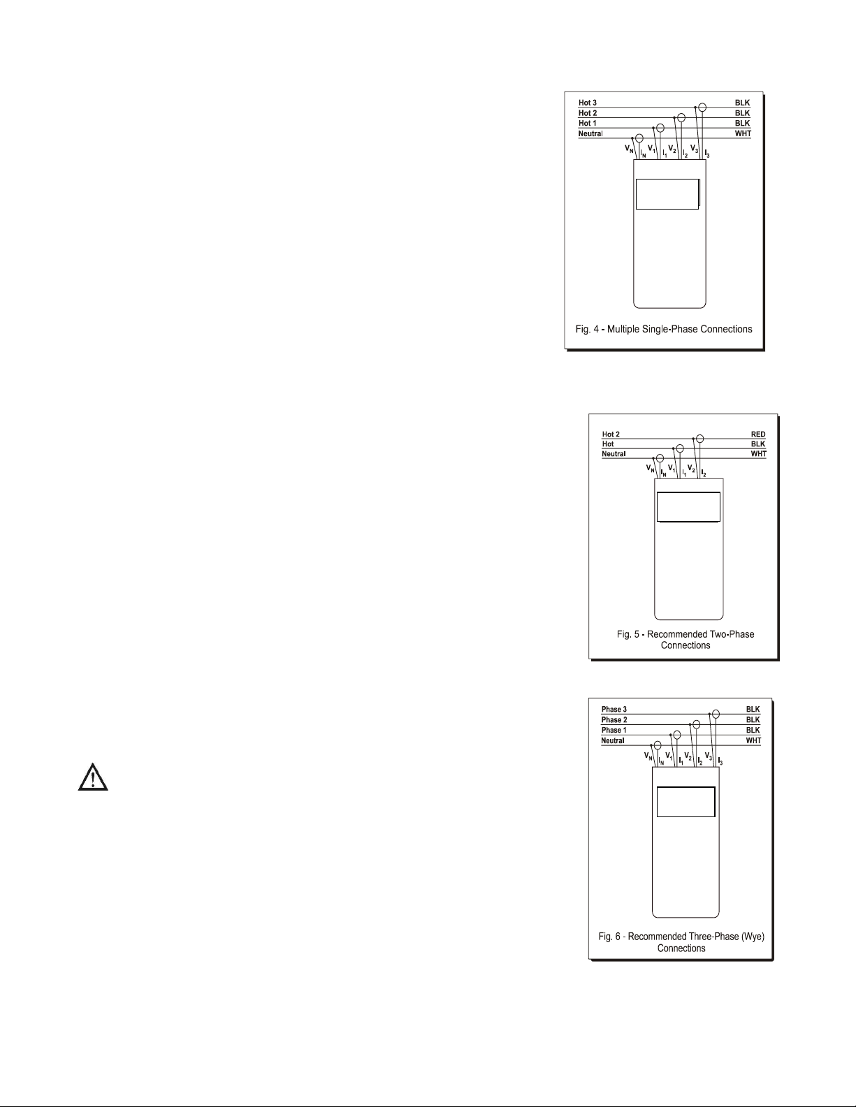
Connecting to Multiple Single-phase Loads
Figure 4 presents a means to monitor 3 single-phase loads
simultaneously. The loads must all share the same neutral voltage
connection. If the loads run off the same line voltage, connect V1, V2,
and V3to the same "hot" wire. I1, I2, and I3serve the 3 loads. This
approach can also be used to evaluate the current of a 4th load, but
the power used by that load will not be calculated.
In this configuration, the voltage, current, and power of each load can
be displayed directly or graphed on your PC using our PSM software.
Connecting to Split-Phase (Two Phase) Power
Fig 5 shows the recommended connections to a split-phase system as found in commercial and
residential facilities, when measuring the supply to two single phase loads. There are two "Hot" wires
180 degrees out of phase with each other and sharing the same neutral.
Appliances such as ovens that require 240V will span across both hot
wires. When evaluating the power for a load spanning the two phases,
remove the VNvoltage lead since it may affect the power factor readings
of each phase.
In this configuration, a reading of V1N is of hot-neutral and V2N is hot2-
neutral. INdoes not need to be connected and VNshould not be
connected when the load spans the two phases. The power associated
with one hot is measured as phase 1, the power of the other hot is
measured as phase 2. In phase-neutral measurement mode, the voltage
readings will be from hot-to-neutral. If you change the measurement
mode to phase-phase, V12 will be the hot-to-hot voltage that serves the
high power appliance.
Connecting to Three-Phase Four-Wire (Wye) Power
Figure 6 presents the recommended connections to a three-phase
system with voltages referenced to neutral, a "phase-neutral" or “three-
phase four-wire wye” configuration.
Be sure to follow the safety warnings of the previous sections
before making the connections.
Although the current of each phase is carried by neutral, neutral current
is generally relatively small since the currents of the 3 phases largely
cancel each other in the neutral leg. In a perfectly balanced system the
current in neutral would be zero.
In a wye system, each phase is essentially independent of each other.
For this reason, the power factor of each phase has direct meaning, but
the total power factor is less meaningful. Most commercial wiring and
newer industrial wiring is in this wye configuration.
ATPOL II
ATPOL II
ATPOL II
14
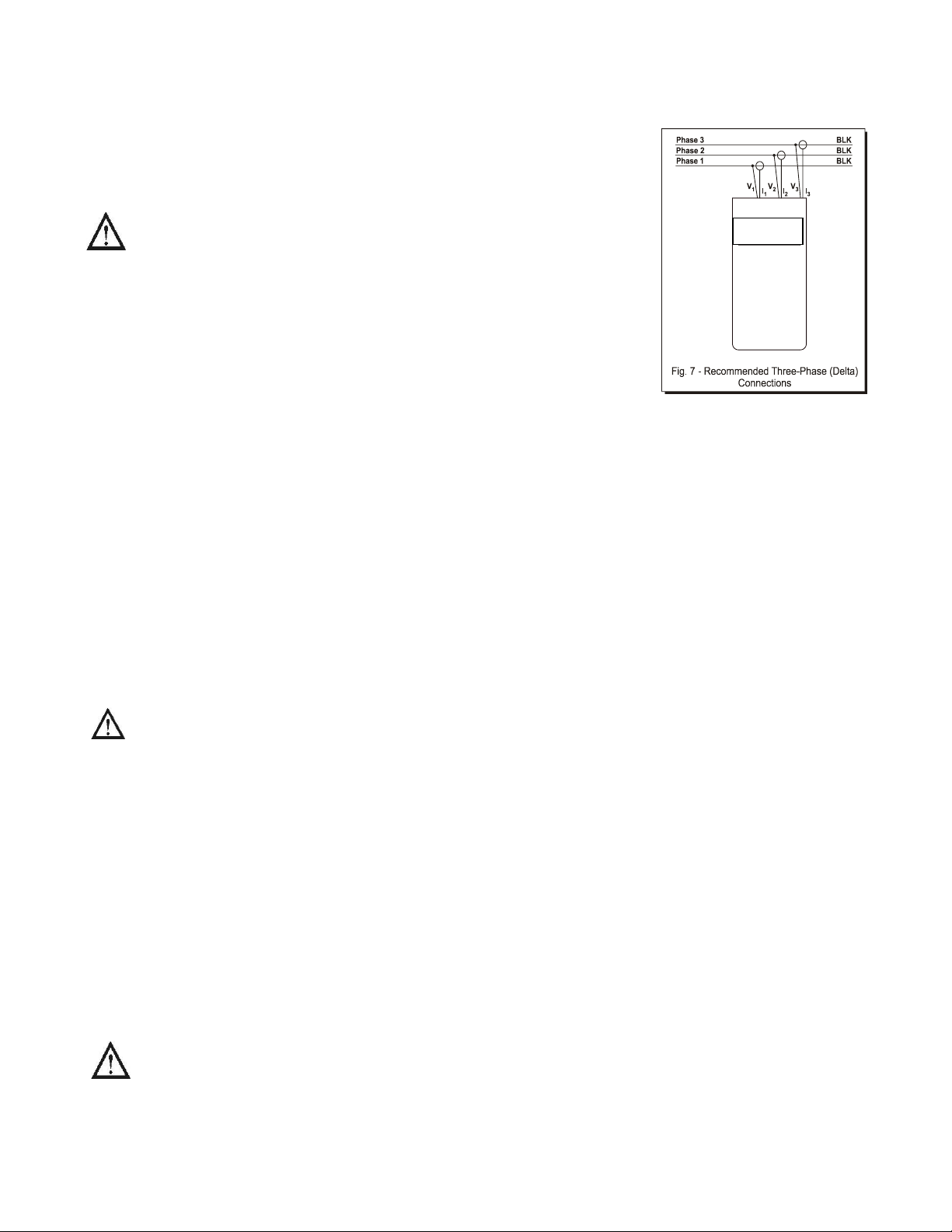
Connecting to Three-Phase Three-Wire (Delta) Power
Figure 7 presents the recommended connections to a three-phase system
with voltages referenced to each other instead of to neutral. This is a
"delta", "phase-phase", or “three-phase three-wire” configuration.
Be sure to follow the safety warnings of the previous sections
before making the connections.
Please Note: Do not connect the VNinput to anything when
measuring in phase-phase measurement mode. This may affect the
measurements associated with individual phases.
In a delta configuration, current flowing in each phase is due to the
interaction of 2 different voltages. For instance I1current is the resultant
of V12 and V31. Normally, there is no way to determine what portion of the current is due to which
voltage. For this reason, only the total power and total power factor have definite meaning in a delta
system. However, comparing the power factors of each phase can be valuable for spotting a
connection problem or problem with the load.
Delta power is common in motors and older industrial sites.
A variation of delta is “four-wire” (or “center-tapped”) delta (see figure 1D). In this configuration, if the
main interest is in measuring phase-neutral voltage, then connect the neutral voltage to the neutral
input for more accurate voltage readings
Connecting to Three-Phase Four-Wire Delta Power
Figure 6 presents the recommended connections to a three-phase delta system where a neutral is
provided from the center of one of the phases.
Be sure to follow the safety warnings of the previous sections before making the
connections.
This type of system allows delivery of both three-phase and single-phase power. The three-phase
power is typically 240V for running motors. The dual single-phase power is typically 120V for running
lights and small equipment, from one power service. It also provides 208V. Depending on what you
intend to monitor, it may be appropriate to set ATPOL II in phase-phase voltage measurement mode (to
monitor three-phase loads or to look at total power) or in phase-neutral voltage measurement mode (to
monitor single phase loads). Although the selection of voltage measurement mode affects what voltage
levels are displayed and recorded (phase-phase versus phase-neutral), it does not affect the power and
power factor calculations.
Connecting to Three-Phase Grounded Delta Power
Figure 7 presents the recommended connections to a three-phase system with one phase tied to
ground. No connection is made to the neutral input. One of the phases originates from ground.
Be sure to follow the safety warnings of the previous sections before making the
connections.
ATPOL II

15
Connections Using 2 Current Approach
In the previous sections, the approach used to measure power has been
based on determining the power of each phase and then summing them
to get the total power. The 2 current approach (figure 8) allows you to
determine the total power from measuring only 2 of the 3 currents and
combining them with the 3 voltages of the three-phase circuit. The
disadvantage of this approach is that you cannot determine the power,
power factor, or VA of each individual phase and, of course, you cannot
record the current of one of the active phases.
A necessary use for this type of connection is to measure utility power
where only two metering CTs and three PTs are provided. After hooking
up to the CTs and PTs, you enter the input ratios into ATPOL II (see the
Setting Input Ratios section) in order to record the correct values (the
values on the primary side of the transformers).
A different motivation for using this type of connection is to save time and money. By only connecting
to 2 of the 3 currents, a small amount of time can be saved. The frugal user appreciates this approach
because he can save the cost of one current probe when buying a system in order to measure total
power. Another motivation occurs in situations where one of the phases cannot be measured due to
accessibility.
This approach is also called the “2 wattmeter approach” because it mimics how two single-phase
wattmeters can be used to measure total three-phase power. The equation that it depends on is:
( ) ( )
total ab a cb c
W V I V I
. This equation is true regardless of the harmonic content of the
voltages and currents present. A few words of caution are required, however. First, a volt-ohmmeter
cannot be used for this calculation. That is because the equation depends on the instantaneous
products of voltage and current. That is normally quite different from the product of the RMS voltage
and RMS current. Second, a single-phase wattmeter should not be used for this calculation since
conditions normally change second by second and hence adding the watts of two different setups will,
at best, give a “feel” for the correct true power. Lastly, it is more important to make the connections
correctly in this approach since an error will not be obvious and there is no way of recovering to an
educated guess of the correct power reading.
Refer to the Phase-Neutral vs. Phase-Phase vs. 2 Current Mode section for how to operate the unit in 2
current probe mode.
Connections To a 3 CT / 3 PT Metering Circuit
Sometimes it is helpful to monitor a load indirectly, by connecting ATPOL II to a metering circuit in front
of the load. A few circumstances where this is the case:
the CTs (current transformers) and PTs (potential transformers) of the metering circuit are readily
accessible for connecting to, whereas the actual load carrying cables are not
the conductors carrying the load are physically too large for your current probes to fit around them
the load current is too large to be read by the current probes you have
the voltage delivered to the load exceeds the 600V insulation limit of the current probes
the voltage delivered to the load exceeds the 600Vrms rating of ATPOL II and you do not have
other high voltage probes.
ATPOL II

16
A typical metering circuit showing ATPOL II connected is shown in figure 9.
This circuit has three CTs and, if higher voltage is present, may have three
PTs. It is typical for metering a three-phase four-wire wye type service. The
currents flowing to the load are considered the “primary currents”. Those
currents are “stepped down”by each CT to a “secondary current” according
to the ratio of the CT printed on its rating plate. A typical value would be
600:5 (120:1). The output of each CT must have some burden across it for
the secondary current to flow. The current probes of ATPOL II are clamped
around the secondary of each CT. Make sure to use current probes that are
suited for accurate measurement in the 0-5 amp range. The AT6003 is best
for this. The AT6001 or AT6002 may be acceptable, depending on the
current level.
Once the current probes are attached, it is best to set the input ratios for each
of the current probes (see the Setting Input Ratios section). This will allow
the displayed values and logged values to reflect the primary current level
instead of the secondary current level. This in turn allows accurate power and cost readings without
having to multiply the results times some ratio. Remember that these ratios are reset to 1:1 whenever
ATPOL II is turned off.
Similarly, the PTs take a primary voltage and step it down to a secondary value. If the primary voltage
is below 600Vrms, you will not need to hook up to the PTs (in fact, there will probably be none present).
The ratio of the stepping down of the voltage will be printed on the rating plate of the PT. Typically this
would be 2400:120 (20:1). As with the CTs, this ratio should be entered into ATPOL II (see the Setting
Input Ratios section) to simplify interpreting the results.
Connections To a 2 CT / 2 PT Metering Circuit
Figure 10 shows recommended connections to a metering circuit with only 2
CTs or 2 PTs. This type of metering circuit may be preferable when cost is an
issue (less instrument transformers are used) or when metering a delta service
with no reference to neutral. The discussion of the previous section
(Connections To a 3 CT / 3 PT Metering Circuit) applies to this circuit as well,
with one important exception. If you clamp onto the CTs, rather than clamping
onto each of the primary currents directly, ATPOL II must be operating in the 2
Current Probe mode of operation (see the Phase-Neutral vs. Phase-Phase vs. 2
Current Mode section).
Connections To an Open Delta (3CT / 2PT) Metering Circuit
In the open delta configuration, two PTs and 3 CTs are available. Make the
voltage connections as shown in figure 10 of the Connections to a 2CT / 2PT
Metering Circuit section. For current connections, connect the phase 1 and phase 3 probes as shown
in figure 10 and attach the phase 2 current probe to the phase 2 CT. You will not need to operate in the
2 Current Probe mode of power measurement since there are 3 currents being monitored.
ATPOL II
ATPOL II

17
Connecting to Line-To-DC (LDC) Converter Accessory
The Line-To-DC Converter accessory converts the voltage that is being
monitored into DC voltage to run and charge ATPOL II. The applications of
this option are:
Electrical room monitoring where a 120V outlet jack is not available for
your charger
Monitoring where an extension cord from a 120V outlet jack would be a
safety hazard
Monitoring on a rooftop, power pole, or power pad
Reliable charging for the meter when there is concern that an available
120V outlet jack may be switched off by other personnel
Simplified monitoring connections (no need to think about powering
ATPOL II when installed inside a CASW weather-resistant case.
Figure 11 shows the correct method of connecting the LDC to ATPOL II. The LDC comes with two long
red input leads that end with a stackable safety banana plugs. These stackable plugs are to be
inserted directly into two of the inputs of ATPOL II. If you are monitoring power without a neutral, we
recommend plugging them into the V1and V2inputs. If an external neutral is present, we recommend
plugging them into the V1and VNinputs. In any case, there needs to be a potential between them of at
least 100 Vrms and no more than 500 Vrms from 50 Hz or 60 Hz power.
The LDC also comes with in-line fuse assemblies plugged into the stackable plugs. These red
assemblies contain 1000V fuses. They provide protection if a short should occur in the LDC. The two
voltage leads that would normally be plugged into ATPOL II are plugged into the loose ends of the in-
line fuses. At this point, ATPOL II is ready to measure voltages as usual and the LDC is connected in
parallel to two of the inputs of ATPOL II. You may wish to remove the in-line fuse assemblies, plug
your voltage leads directly into the stackable plugs, and plug the in-line fuse assemblies between the
loose ends of the voltage leads and the voltage clips. This provides a connection that is electrically
equivalent to the normal connection, but the fuses are physically as close to the power source as
possible. The advantage of this approach is that if one of the voltage leads gets shorted to ground
(perhaps from being cut by a panel door), a fuse quickly blows, providing added protection.
Note: Do not use the LDC without the in-line fuses being connected between it and the
power source. The fuses are the only circuit protection for the LDC.
When the input side of the LDC is fully connected properly, plug the long DC output plug into the DC
input jack of ATPOL II. The red charging indicator near the jack will light up if everything is operating
and connected properly.
Note: If a fuse is burned out or missing, it will appear that there is no voltage at the
source. Verify that the fuses are working properly before assuming that the source is dead.
Injury may occur if you wrongly assume that the source is deactivated.
ATPOL II

18
Measuring Multiple Parallel Conductors
A common problem with measuring large currents arises when the current
of each phase is carried by several parallel conductors. For instance the
phase 1 current may be carried in 4 parallel conductors, as are phases 2
and 3, resulting in 12 conductors to measure. In this case, the work-
around is to clamp onto just one of the conductors of each phase and
enter an input ratio to record the correct total current of each phase. A
fast way of doing this is to enter an input ratio of 4 : 1 for each phase in
the example of 4 parallel conductors. This may offer adequate accuracy
for your needs. However, experience shows that although the current in
each conductor of the same phase is similar in size, they are typically
NOT identical.
Overcoming the problem of unequal currents in parallel cables takes a few
steps to do it accurately.
1. Put a different probe on each conductor of a given phase and then viewing the currents of each
probe simultaneously (see the Checking Current Levels –Using Checkout Connections section).
2. Start monitoring for 10 seconds or so and then stop monitoring (see the Starting Data Logging and
Stopping Data Logging sections).
3. Press the [Current] key and then the [More] key four times to view the average current for phase 1
(which is actually just one of the conductors of one of the phases). Write it down.
4. Press the [Current] key and then the [More] key four times again to view the average current for
phase 2. Write it down.
5. Repeat these actions in order to get the average current of each of the conductors for the same
time period.
6. Find the total of the average currents of each of the conductors of the same phase.
7. Divide the total of the average currents into the average current of conductor you wish to connect to
during the actual monitoring session. This yields the portion of the total current that flows through
the conductor that will be measured.
8. Set the input ratio of the phase being measured to the number determined in the previous step. For
instance if the total of the average currents was 1000 amps and the average current of the probe on
the conductor you wish to use during the actual monitoring session had an average of 26 amps,
then enter an input ratio for that phase of 0.26 : 1.
9. Perform steps 1 through 8 for each phase.
10. Now connect each probe to the chosen conductor of each phase and begin monitoring. All the
readings and logged values will be substantially correct.

19
Measuring Currents Below the Range of the Current Probe
A problem with measuring smaller currents arises when the current to be measured is below the range
of the current probe. In such cases, the current may not be read or the reading may be inaccurate. In
addition, any waveforms that are captured will have excessive noise on them.
If you are using a flexible current probe, you can simply wrap it around the conductor twice in order to
double the magnetic field strength. This can get it in the measurement range and it boosts the signal to
noise ratio. If you use this method, set the input ratio for the current probe to 1 : 2 (see the Changing
Input Ratios in ATPOL II section).
If the current to be measured is small, it may be acceptable to open the circuit
and insert an extra length of wire that is wound up into a coil of 10 turns.
Clamping your current probe around this extension coil will boost the signal
strength 10 times and allow accurate reading of small currents. If you use this
method, set the input ratio for the current probe to 1 : 10 (or however many
turns there are in the coil).

20
Turning ATPOL II On
Connecting to Power
Although ATPOL II comes with Li-ion rechargeable batteries, those batteries are intended to keep
ATPOL II functioning during limited power failures and to allow quick measurements without the bother
of always having to find a 120 Vrms source. When fully charged, the batteries can power the unit for up
to 12 hours.
For longer usage and to recharge the batteries, your unit has been supplied with a wall-mount power
supply. To use this power supply, simply plug it into any 120 Vrms source (use the AT6200-115
charger for 120Vrms and the AT6200-230 for 220V) and then plug its barrel-type plug into the 12 VDC
input jack on the right side of ATPOL II. If charging voltage is available, an LED indicating light will
immediately shine through the hole located to the right of the input power jack. Allow 4 hours to fully
charge the unit.
If you wish to operate ATPOL II without being tethered to a power outlet, the Line-to-DC converter
accessory offers the ability to power an ATPOL II directly off the line voltage being monitored. It works
with 50 Hz and 60 Hz power, operating off 100 to 480 Vrms input, single-phase or three-phase. All this
versatility is obtained without setting switches or changing connections.
If you need to operate the Line-to-DC converter off of 600V phase-to-phase service, connect one
input to a hot phase and the other input to neutral.
The internal batteries are automatically charged when the wall-mount supply is connected to the unit (or
when ATPOL II is connected to the Line-to-DC converter accessory).
The internal batteries are not to be replaced by the user. Only batteries provided by ATP are to be used
in ATPOL II.
Turning ATPOL II On
Simply press the green on/off button at the lower right of the keypad on the front panel and ATPOL II
will be operating (pressing the button again, turns the unit off). The message that the meter is
performing a system test will appear for a few seconds and then the greeting will appear. You can
change this greeting at any time by following the directions in the administrative functions that are
accessed by pressing the [Admin] key. Please note that turning ATPOL II on does not automatically
start monitoring and logging. Refer to the Putting it all Together (Monitoring for the First Time) section
for how to start monitoring and logging.
Turning ATPOL II Off
To turn ATPOL II off, simply press the green on/off button at the lower right of the keypad on the front
panel. This provides a graceful software/firmware shutdown. If pressing the button briefly does not
turn the meter off, press the on/off button down and hold it down for 3 seconds to force a hardware
shutdown. If this is a recurring problem, contact support@alltestpro.com.
Table of contents
Other ALL-TEST PRO Measuring Instrument manuals

 instruction manual")


