Stack TPMS Lite User manual

TPMS Lite Installation Guide ST542119-002
TPMS Lite
Installation Guide
Sensor Installation
Antenna Installation
Configuration Software
Display Gauge
CAN Message Formats
Troubleshooting

TPMS Lite Installation Guide ST542119-002
2
This page intentionally left blank.

TPMS Lite Installation Guide ST542119-002
3
1. TPMS Lite Sensor Installation
_________________________________________________________
Tools Required
The following tools will be required for the fitting process:
Torx (R) T20 Screwdriver /Torque driver (RS 662-608, DemonTweeks BIKTORXKEY)
4Nm Torque screwdriver ¼” Drive (e.g. Teng Tools 1492SD)
11mm x 50mm Socket (e.g. Teng Tools M140611-C)
Parts Description
TPMS Fitting Kit
A: Self Locking Torx Screw
B: Sensor
C: Valve
D: Spacer Ring
E: Collar Nut
F: Valve Cap
G: Installation Bar
TPMS Lite Installation Guide ST542119-002
4
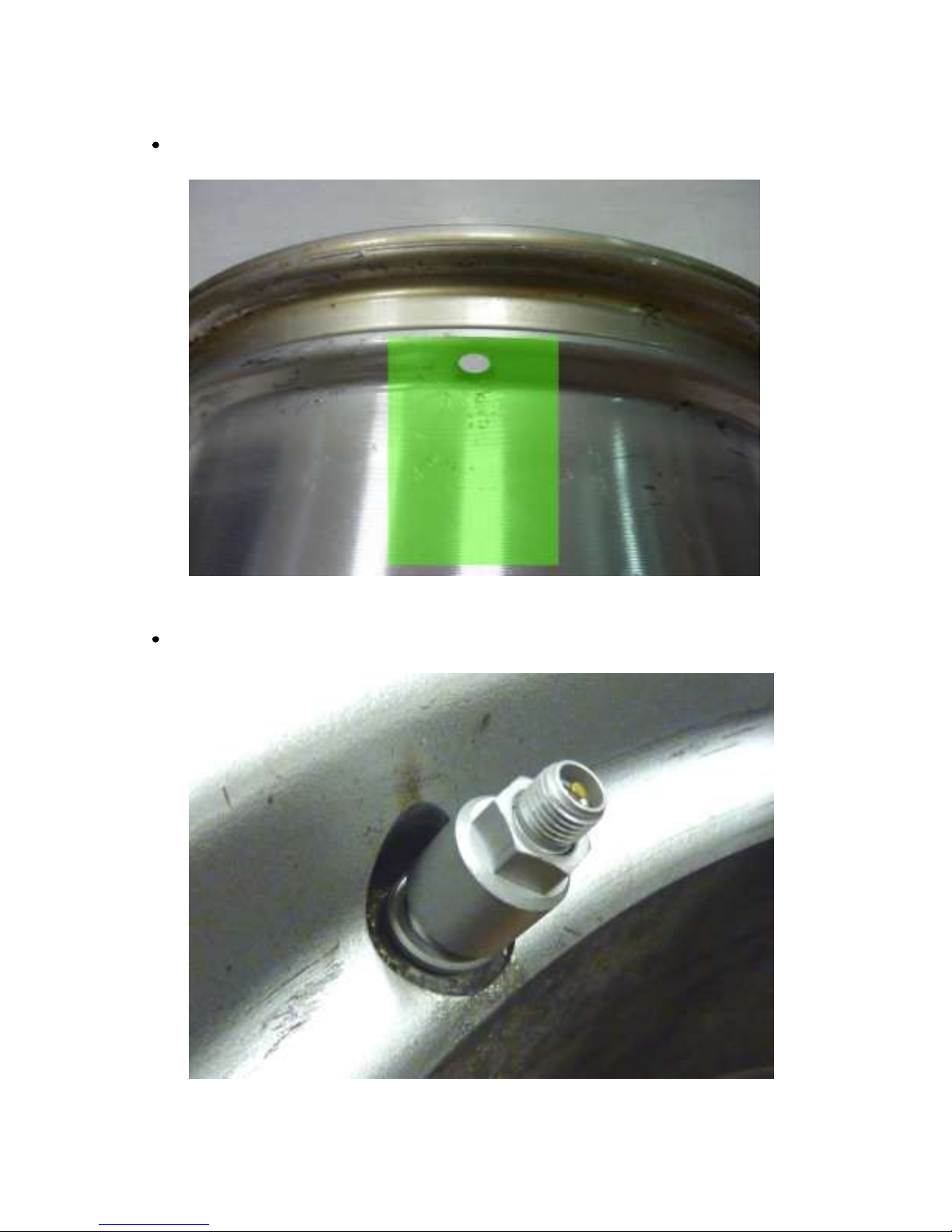
Valve Fitting
Ensure the wheel rim is cleaned and degreased around the valve and wheel well (Green area).
Insert valve into wheel rim. Fit the spacer ring (D) and then the collar nut (E) finger tight.
TPMS Lite Installation Guide ST542119-002
5
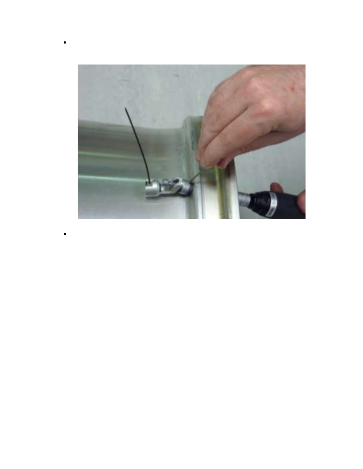
Insert the installation bar (G) into the valve body and tighten the collar nut (E) to a torque of
4Nm +/-0.5Nm
Press the sensor down into the wheel well so that base of the sensor is touching the rim.
NOTE: The base of the sensor must make contact with the wheel rim.
NOTE: The sensor antenna must point away from the centre of the wheel.

TPMS Lite Installation Guide ST542119-002
6
Tighten the Torx screw (A) to 4Nm +/- 0.5N
Once tightened check the sensor is still in contact with the rim.

TPMS Lite Installation Guide ST542119-002
7
The sensor is now fitted correctly to the rim and ready for the tyre mounting.
NOTE: It is recommended to fit some identifying mark on the outside of the tyre to indicate
the rim is fitted with a TPMS sensor. This will alert tyre fitters to the fact there is a sensor
fitted and extra care should be taken when mounting/dismounting the tyres.
TPMS Lite Installation Guide ST542119-002
8
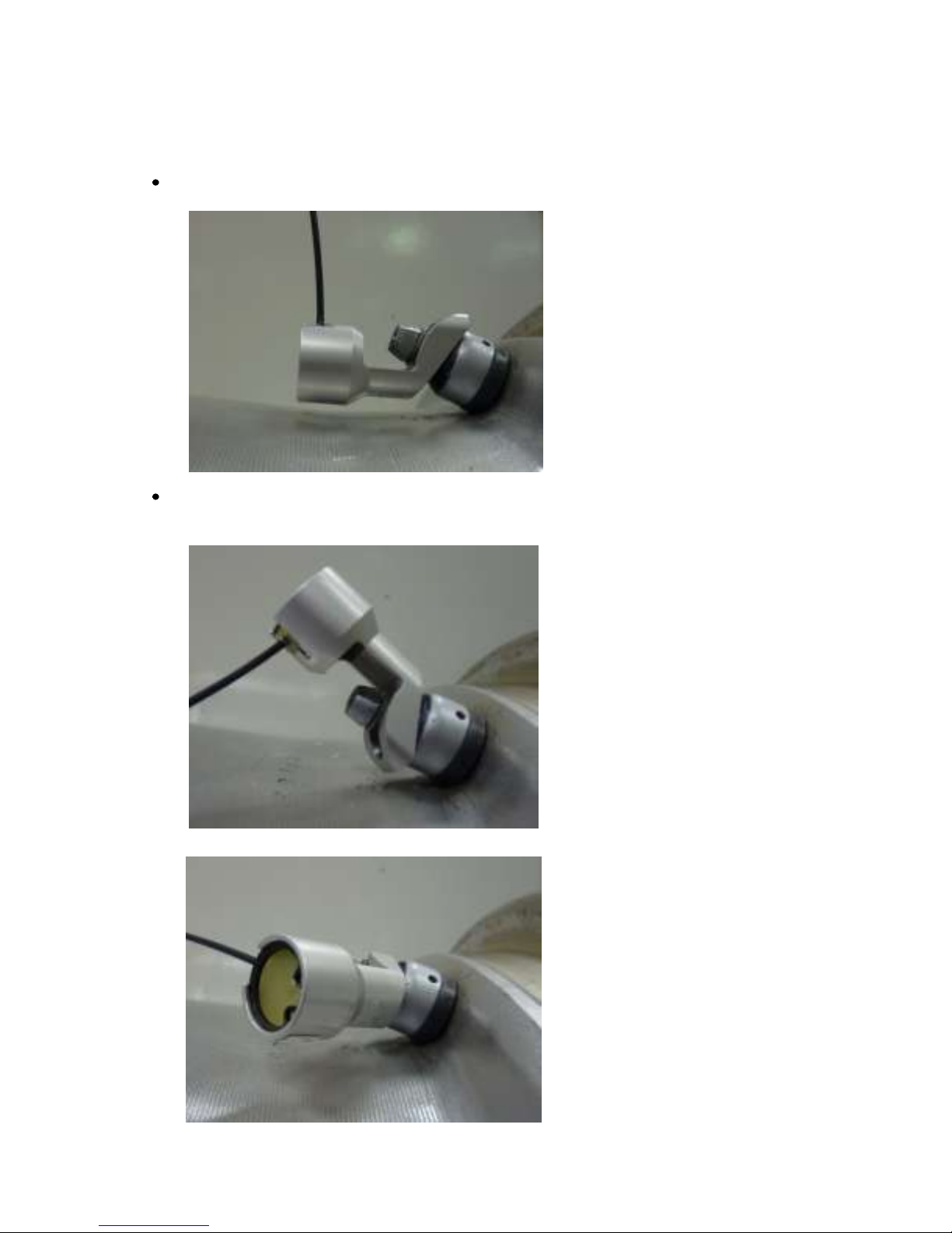
Incorrect Fitting Examples
The following are examples of bad fitment that will degrade the performance of the system:
Sensor not in contact with rim.
X
Sensor antenna pointing away from wheel centre and sensor base not
touching rim.
X
X

TPMS Lite Installation Guide ST542119-002
9
2. TPMS Lite Antenna Installation
_________________________________________________________
Introduction
This chapter will describe the fitting of the TPMS Dual-Band Antennas to a vehicle. Please ensure you
read this guide carefully to obtain the best performance out of the system.
Antenna Details
The Stack TPMS antenna is an advanced Dual-Band Antenna (DBA). For optimum system performance,
care should be taken to fit the antennas according to the guidelines in this document. The system
performance can be impaired with poor antenna placement.
The antenna picks up 2 signals. The first is the SAW (433 MHz). This is the signal used to measure
pressure and temperature. The second signal is the RFID or Sensor ID (868 MHz). This is used to pick up
the sensor serial number and the calibration details. Both signals are required for successful operation of
the TPMS system.
Antenna Placement
The goal of choosing an antenna position is to achieve the strongest signal strength for both SAW and
RFID over the widest wheel rotation. There will be some points of wheel rotation where a signal will not
be strong enough to take a measurement. These are generally called NULLS. It is common to have 3 nulls
per rotation of the wheel for the SAW signal.
The antenna must be placed as close as possible to the wheel.
The antenna front “box” must be directly in line with the tyre sidewall

TPMS Lite Installation Guide ST542119-002
10
The antenna must be mounted radially from the centre of the tyre.
The Ground plane can point towards or away from the centre of the wheel.
The antenna can be mounted behind NON conductive panels (Kevlar, GRP)
In a typical installation you will achieve 90-120deg of RFID coverage and 270 degrees of SAW coverage. It
is important to optimise the RFID coverage to maximise the area at which the RFID can be read over.
Typically the RFID cannot be read outside the area shown above. This should not be a concern when
finding an antenna position as long as you have the coverage shown above.
It is important to get to as close to 120deg of rotational coverage as possible for optimum system
operation.
For ease of installation we recommend you use the Monitor mode in the TPMS configuration software.
This can be found on the Monitor tab of the configuration software. Selecting simple monitoring mode
will allow you to see the following information.

TPMS Lite Installation Guide ST542119-002
11
The SAW_Strength and RFID_Strength indicators can be used to tune the antenna position.
Antenna Placement
The antenna installation is normally done in several parts. The first is to choose an initial location for the
antenna based on the above guidelines and measure the signal strength during a complete wheel
rotation. This will give a baseline to work from. Then the process is repeated with a new antenna
position. Each time the goal is to increase the wheel rotation coverage or signal strength.
Note: Please ensure that the antenna is secured onto the car with Velcro/dual lock when taking
measurements. Holding the antenna can lead to signal variations.
NOTE: It is strongly recommended that you spend the time at this stage to find the optimum antenna
position as it will significantly reduce the potential for problems later on.
TPMS Lite Installation Guide ST542119-002
12
Antenna Placement Restrictions
If you have to mount the antenna to a conductive surface (metal, carbon) then you MUST
space it off the surface by 10mm. Dual lock is ideal for this.
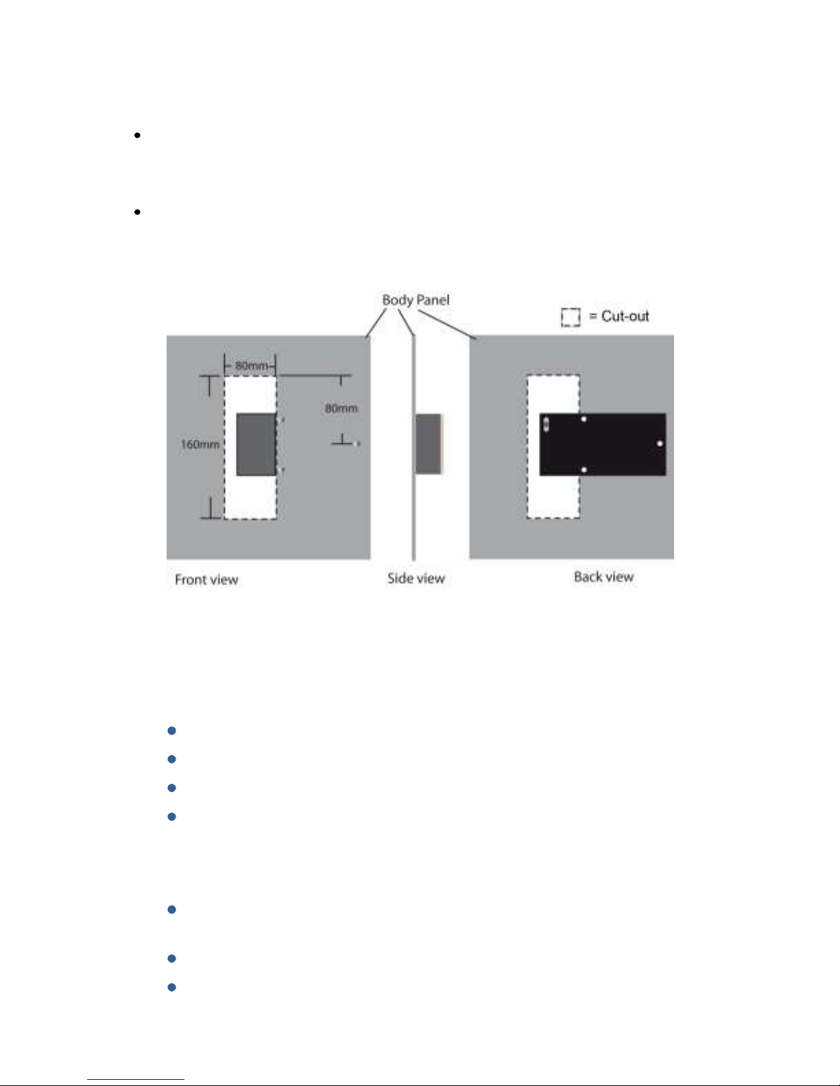
Should you have to mount the antenna behind a conduction surface then please ensure that
you cut a window for the antenna that is the same as the dimensions below. This is essential
for the correct operation of the antenna.
Antenna Do’s and Don’ts
Do
Ensure the antenna is mounted following the guidelines in this manual
Take the time to ensure the antenna placement and tuning is as good as possible
Make sure the RFID signal can be read over at least 90deg of wheel rotation
Ensure the SAW signal is as strong as possible throughout the whole wheel rotation
Don’t
Mount the antenna behind a conductive panel (Carbon, Metal) without first making the
hole as above in the panel
Don’t hold the antenna when performing the installation. Use dual lock
Don’t cut or modify the ground plane of the antenna. This is crucial for correct
operation.
TPMS Lite Installation Guide ST542119-002
13
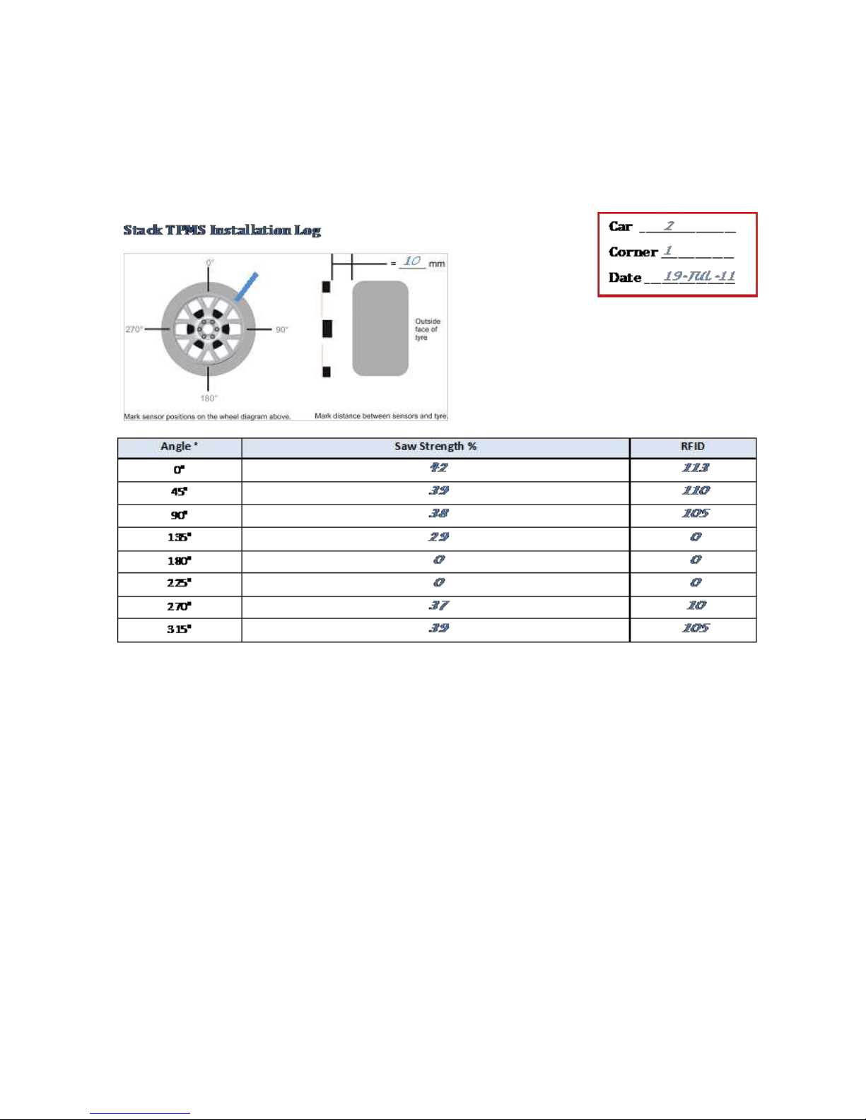
Example Antenna Installation Log
Keeping a hard copy log during antenna installation is a useful way of capturing the data in the field but
can also be helpful in aiding a Stack engineer diagnose possible problems with an installation. A sample
log may look like this:
A blank example log for your use is printed overleaf.

TPMS Lite Installation Guide ST542119-002
14
TPMS Lite Installation Guide ST542119-002
15
3. TPMS Lite Configuration Software Set-up
_________________________________________________________
Introduction
This guide will describe the TPMS configuration software and how to use the features in it. This software
can be used to configure the TPMS control unit and to monitor the values in real time being measured.
System Requirements
The TPMS configuration software is compatible with the following 32-bit and 64-bit operating systems:
Microsoft® Windows 7
Microsoft® Windows Vista SP2
Microsoft® Windows XP SP3
Connecting to the TPMS Interrogator
1. Double click on the TPMS Configuration Utility icon on the desktop or by
navigating to Start->All Programs->Stack Limited->TPMS Configuration Utility.
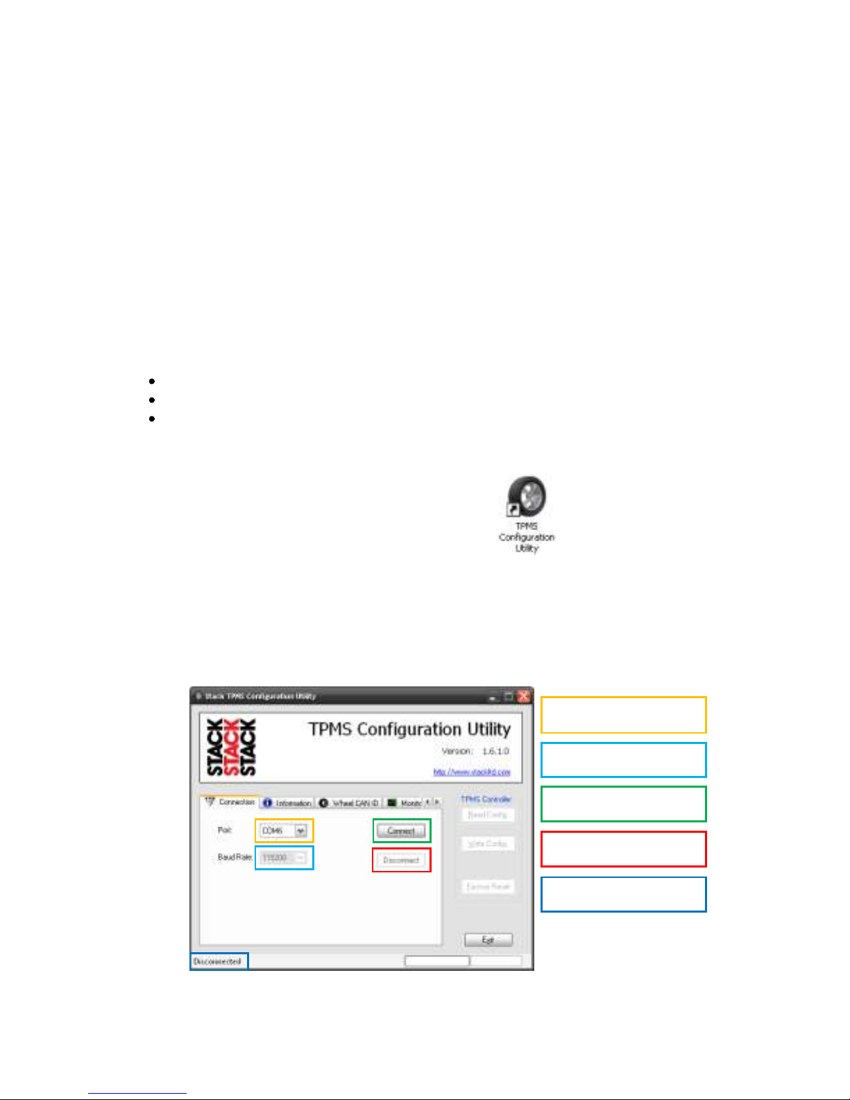
2. After a few seconds, the main screen will appear. Please take some time to become familiar
with this screen and the layout. Some of the options will remain greyed out and non-
selectable until a connection is made to the TPMS interrogator.
Note: Please ensure that 115200 is selected as the Baud Rate.
Select Serial port
Select Baud Rate
Connect to Box
Disconnect from Box
Connection Status
TPMS Lite Installation Guide ST542119-002
16
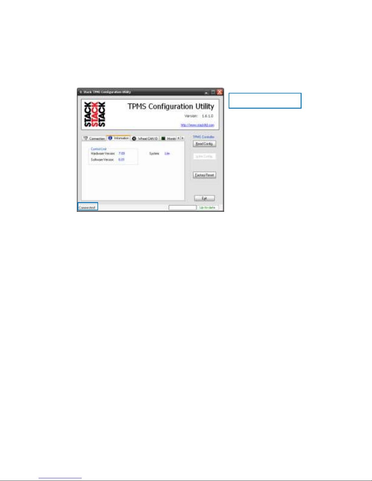
3. Select the Serial (COM) port you have connected the TPMS Control unit to and press the
Connect button. If the connection is made to the box the program will display to the
Information Tab and display the information for the unit. To confirm a connection has been
made the Connection Status changes from Disconnected to Connected.
Reading and Writing Configurations
The software will automatically read the configuration from the interrogator when the Connect
button is pressed.
Any changes that are then made to the configuration will need to be written to the interrogator.
This is done with the Write Config button. The Write Config button is only activated when the
configurations of the interrogator and config software do not match. The Config Status will show
Up-To Date if they match and Modified if they don’t.
The Read Config button can be used to get the configuration from the interrogator at any time.
Connection Status

TPMS Lite Installation Guide ST542119-002
17
CAN Configuration
The TPMS interrogator has a fully configurable CAN bus output. This is used to send data to the
TPMS gauge and can also be used to connect the system to a data logger.
Note: The gauge is fixed to received CAN data on ID 1440 (FL), 1441(FR), 1442(RL) and 1443(RR).
The gauge expects and will only function with these CAN IDs.
To configure the CAN options click on the Wheel CAN ID tab.
CAN IDs
The interrogator outputs a CAN data message per wheel. By default the interrogator
outputs on IDs 1440 to 1443. These are the IDs the TPMS gauge reads. The CAN IDs can
be changed to suit the system the TPMS is connecting to.
Read Config
Read Config
Config Status
CAN IDs
CAN Receive ID
Gauge Fitted
CAN Bit Rate

TPMS Lite Installation Guide ST542119-002
18
CAN Receive ID
The TPMS interrogator can receive data over the CAN bus.
Display Fitted
Unchecking this option stops the TPMS interrogator sending the CAN messages to the
gauge. This is useful if the gauge CAN IDs are taken by another device on the system and
should not be sent out by the TPMS interrogator.
Checking this option allows the CAN IDs of the interrogator to be changed while keeping
the gauge functionality.
CAN Bit Rate
The bit rate of the TPMS interrogator can be selected. If the TPMS system is not being
connected to an external data logger then this can be left at 1Mbit. If the system is
being connected to a data logger, set this to the bit rate of the system you are
connecting it too.
Real-time Monitoring
The configuration software can be used to display real time information from the TPMS interrogator.
This is useful during installation and the running of the system.
To enable the real time monitor click the Monitor tab, then click the Monitor button
Note: The monitor window can be resized by dragging the bottom right corner to the size desired.
Front Left
Front Right
Rear Left
Rear Right
TPMS Lite Installation Guide ST542119-002
19
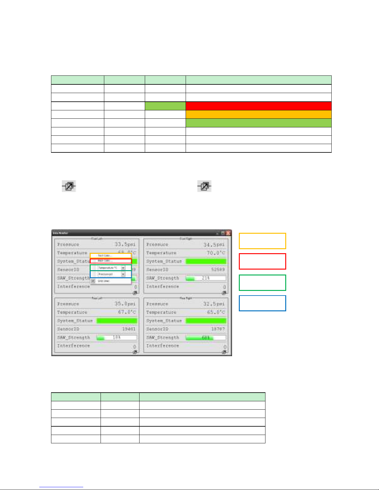
The Monitor window displays the values from each of the 4 wheels. The monitored parameters are listed
below.
Parameter
Range
Optimum
Description
Pressure
0-320psi
N/A
Measured pressure
Temperature
0-320DegC
N/A
Measured temperature
System Status
Green
No Sensor Detected
Sensor Detected - Trying to measure
Sensor Detected - Measuring Pressure and Temp
Sensor ID
0-65000
N/A
ID of sensor on that corner
SAW Strength
0-100%
100%
Strength of the pressure and temperature signal
Interference
0-100%
0%
Amount of external radio interference
The monitor window allows for a single corner to be expanded to fill the screen. This also allows that
corner to update faster allowing for more instantaeous feedback. To expand a corner to full screen, click
the icon. To return to the 4 corner view click the icon again.
It is possible to customise the monitor window. Right click on any of the corner displays and a pop-up
menu will appear.
The description of each parameter can be found in the table below.
Parameter
Range
Description
Text Colour
-
Sets the text colour for the corner
Back Colour
-
Sets the background colour for the corner
Temp Units
DegC/DegF
Sets the temperature display units
Press Units
Psi/Bar
Sets the pressure display units
Grid Lines
Yes/No
Shows or hides the grid lines
Text Colour
Back Colour
Temp Units
Press Units

TPMS Lite Installation Guide ST542119-002
20
To close the monitor window click the red X in the corner . This will close the monitor window and
return to the main program.
Importing Sensors
The TPMS Lite system allows for 3 sets of wheels to be configured. Each set can contain up to 4
sensors. The sensors need to be imported to the TPMS sensor library before being configured for
use in the box. The action of importing a sensor in also authorises it for use with the system.
Note: To add a sensor to the library the TPMS config software must be used. The library is stored
on the local PC.
Sensor Importing and Authorisation
The pincodes can be found on the outside of the sensor packaging and on the id card supplied with
each sensor. If you have difficulty locating your pin code please contact your dealer.
To import pincodes click the Pincodes tab.
Click the Import button and select the location on the computer where the pincode files
have been saved, then click OK.
NOTE: It is possible to enter the pincode without a file by entering it into the pincode input
and clicking the add button. This authorises and adds the sensor to the library.
Import Pincodes
Manual Pincode
Other manuals for TPMS Lite
2
Table of contents
Other Stack Accessories manuals


![AEM Lambrecht Meteo u[sonic]WS7 manual](/data/manuals/12/e/12e6t/sources/aem-lambrecht-meteo-u-sonic-ws7-manual.jpg "AEM Lambrecht Meteo u[sonic]WS7 manual")


