Turner Designs Turbidity Plus with Integrated Wiper User manual

User’s Manual
April 20, 2017
P/N 998-2187
Revision B
TURNER DESIGNS
1995 N. 1st Street
San Jose, CA 95112
Phone: (408) 749-0994
FAX: (408) 749-0998

Turbidity Plus Sensor
998-2187 Rev. B Page 2
Table of Contents
1.
Introduction
1.1
Description
4
2.
Inspection and Setup
2.1
Instrument Checklist
5
2.2
Housing Configurations
5
2.3
Optional Accessories
5
2.4
Functional Test for Turbidity Plus with connector
6
2,5
Functional test of the wiper for the Turbidity Plus with connector
7
3.
Calibration
3.1
Direct Concentration Calibration for Turbidity Plus
8
4.
Integration
4.1
To take measurements
9
4.2
To trigger wiper
9
5.
Maintenance and Warranty
5.1
Maintenance
10
5.1.1
Rinsing
10
5.1.2
Care for the bulkhead connector
10
5.1.3
Cleaning the Optics
10
5.2
Warranty Terms
10
5.3
Warranty Service
11
5.4
Out of Warranty Service
11
Appendices
A
Specifications
13
B
Recommended Measurement Practices
14
C
Pigtail Cable and Connector Information
15
D
Functional Test for Turbidity Plus with no Connector
16

Turbidity Plus Sensor
998-2187 Rev. B Page 3
WASTE ELECTRICAL AND ELECTRONIC EQUIPMENT (WEEE)
DIRECTIVE
Turner Designs is in the business of designing and selling products that benefit the
well-being of our environment. Accordingly, we are concerned with preserving the
surroundings wherever our instruments are used and happy to work with customers
by complying with the WEEE Directive to reduce the environmental impact resulting
from the use of our products.
WEEE Return Process:
To arrange the return of an end-of-life product, proceed as follows:
If you purchased your instrument through a Turner Designs Distributor please
contact your local representative. They will instruct you where to return the end-
of-life product.
If you purchased your instrument directly from Turner Designs please contact
Turner Designs Customer Service
By Phone: 1-408-212-4041 or Toll Free: (877) 316.8049
By Email: Customer Service at support@turnerdesigns.com
Turner Designs will provide a WEEE RMA Number, a Shipping Account
Number, and a Ship to Address. Package and ship the product back to Turner
Designs.
The product will be dealt with per Turner Designs’ end-of-life recycling program in
an environmentally friendly way.

Turbidity Plus Sensor
998-2187 Rev. B Page 4
1. Introduction
1.1 Description
Turbidity Plus is an accurate single-channel turbidity sensor including an
integrated wiper which is triggered by the user. It is designed for integration into
systems from which it receives power and the wiper trigger. Turbidity Plus
delivers a voltage output proportional to the turbidity of the sample which can be
correlated to concentration values by calibrating with a standard of known
concentration.

Turbidity Plus Sensor
998-2187 Rev. B Page 5
2. Inspection and Setup
2.1 Instrument Checklist
The Turbidity Plus Sensor shipment package consists of:
Turbidity Plus Sensor with Integrated Wiper P/N 2180-000
USB Flash Drive (per order) which includes:
User’s Manual
Wiring Guide
CE Certificate
Calibration Test Criteria
2.2 Optional Configurations - Refer to Appendix D for wiring and functional testing:
Turbidity Plus with Integrated Wiper, No Connector P/N: 2180-000-NC.
Turbidity Plus with Integrated Wiper, No Connector, Customer-supplied
wiper blade P/N 2180-000-NCW
Turbidity Plus with Integrated Wiper, No Housing P/N 2180-000-NH
Turbidity Plus with Integrated Wiper, No Housing, Customer-supplied wiper
blade P/N 2180-000-NHW
2.3 Optional Accessories:
Turbidity Plus 8- pin Pigtail Cables with Locking Sleeve, see Appendix C for
more information.
0.6 meter Pigtail Cable with Locking Sleeve P/N 2200-170
5 meter Pigtail Cable with Locking Sleeve P/N 105-0552
10 meter Pigtail Cable with Locking Sleeve P/N 105-0555

Turbidity Plus Sensor
998-2187 Rev. B Page 6
Note: Wires colors shown in steps 2.4 and 2.5 correlate to P/N’s 2200-170,
105-0552, and 105-0555. Third party cables may not have the same color
configuration. Turbidity Plus without connector refer to Appendix D.
2.4 Functional test for Turbidity Plus with connector
To perform a functional check on Turbidity Plus, connect the Pigtail colored
wires to the power supply and multi-meter as shown in Figure 1 below.
Additional Equipment required for functional tests:
DC Power Supply: 6 - 9 VDC, >100 mA
Multi-meter to read: 0 –5 VDC
Note: Supply voltages greater than 9 VDC will result in damage to the
sensor.
Figure 1.
6.00 .015
+ -
DC Power Supply
PSU Pos itive Connection
(Red)
Supply Ground
0 VDC (Green)
3.52
Multimeter
10 VDC
+-
Signal Output
“+” (Blue)
Analog Ground
“-” (Brown)
Black White
No Connection
Turbidity Plus Pigtail Cable
Home Signal
(Yellow)
Wiper Trigger
(Orange)
2
6
4
7
1
5
3
28
5
Turbidity Plus pins Turbidity Plus cable holes
2
4
6
3
1
5
7
82
5
Color Pin Function
Black 1 N/A
White 2 N/A
Red 3 Supply Voltage 6-9 VDC
Green 4 Supply Ground 0 VDC
Blue 5 Signal Out “+”, 0-5 VDC
Brown 6 Signal Ground, “-“, 0 VDC
Yellow 7 Home Signal
Orange 8 Wiper Trigger, 3.2 VDC

Turbidity Plus Sensor
998-2187 Rev. B Page 7
With Turbidity Plus connected as shown in Figure 1 answer questions 1 and 2
by making the following functional tests:
1. Is there voltage output?
The multi-meter should be reading some voltage >0 VDC
2. Does the voltage output change?
Move the light source closer to your hand or a surface and check if the
voltage output increases
Note: A visual test of the LED for Turbidity Plus is not possible because it is
IR which is not visible.
2.5 Functional test of the wiper for Turbidity Plus with connector
To perform a functional check on wiper, connect the Pigtail colored wires to the
power supply and multi-meter following the steps below, shown in Figure 2.
1. Disconnect the blue wire from the meter and connect the yellow wire in its
place. It should read about 0 volts.
2. Briefly touch the orange wire to the power supply ground.
3. The wiper should start rotating and the meter should read about 3.2 volts
until the wiper returns to its home position.
Figure 2.
Note: The sensor has built in protection if the wiper becomes blocked and
cannot move. In this case the wipe will stop and will try to return to the home
position the next time it is triggered.
Warning: Do not move the wiper by hand. This can cause permanent damage
to the sensor.
6.00 .015
+ -
DC Power Supply
PSU Positive Connection
(Red)
Supply Ground
0 VDC (Green)
3.20
Multimeter
10 VDC
+-
Home Signal
(Yellow)
Analog Ground
“-” (Brown)
Black White
No Connection
Turbidity Plus Pigtail Cable
Output Signal
“+” (Blue)
Wiper Trigger
(Orange)

Turbidity Plus Sensor
998-2187 Rev. B Page 8
3. Calibration
Note: To make accurate and repeatable measurements it is important to
keep the sensor clean; see Section 5.1 for information on cleaning your
sensor.Refer to Appendix B - Recommended Measurement Practices.
3.1 Direct Concentration Calibration
Calibrating Turbidity Plus is a simple process requiring the use of calibration
standards which correlate the standard’s known concentration to the voltage
measured for that specific standard.
Turner Designs recommends Amco Clear Turbidity Standards. They are non-
toxic safe solutions consisting mainly of deionized water that come prepared in a
broad range of concentrations and have a shelf life guaranteed for one year.
These standards, optimized for Turbidity Plus, are available from GFS
Chemicals under part numbers 8506 (10 NTU), 8507 (100 NTU), and 8620
(1000 NTU). Follow instructions below to establish a correlation between the
standard’s concentration and the sensor’s voltage response. Use the equation
in step 4 to calculate turbidity values in NTU.
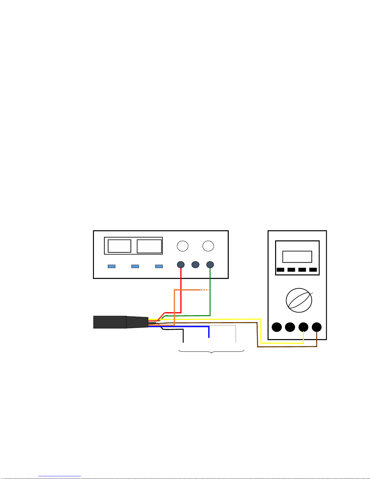
1) Connect Turbidity Plus to a power source.
2) Measure the voltage from a blank sample for the configured gain setting.
Note: A good blank to use for this application is ultra pure or
deionized water.
3) Use a standard of known concentration and create a correlation between the
standard’s concentration and the sensor’s voltage response.
4) Once a correlation has been made, use the following equation to calculate
concentration estimates:
CSample = [(CStd)/(VoltsStd - VoltsBlank)] * (VoltsSample –VoltsBlank)
CStd = Concentration value of standard used for calibration
Csample = Concentration of sample
VoltsStd = Voltage reading from standard concentration
VoltsSample= Voltage reading from sample(s)
VoltsBlank = Voltage reading from blank
Note: Calibration of Turbidity Plus is not required, but recommended. It is
important to note that 0-5 VDC are relative values in relation to the linear
range. However, the qualitative nature of these measurements allows for
inaccuracies in the estimation of concentrations even for calibrated units.

Turbidity Plus Sensor
998-2187 Rev. B Page 9
4. Integration
Once Turbidity Plus has been tested and/or calibrated you can proceed with
integration into your platform. Refer to the power requirements in Attachment A to
make sure that your system is set up correctly. Refer below for typical use with a
data acquisition system wiring configuration.
Note: The wire colors are different for no housing or no connector versions,
refer to Appendix D for the colors.
4.1 Taking measurements:
1. Supply power to the sensor.
2. The digital output to the wiper trigger should normally be a “1” or high and
the digital input from the Home Signal should read “0” or low.
3. Take readings if desired, readings are valid 3 seconds after full power is
applied.
4.2 To wipe:
1. Take the digital output to the wiper trigger momentarily low or “0”. The wiper
will start rotating on the transition from high to low. The pulse low should be
for a minimum of 50 milliseconds. Multiple rotations of the wiper can be
achieved by sending multiple pulses on the trigger signal while the wiper is
rotating. The wiper will rotate the number of pulses it receives.
2. The home signal can be monitored on the digital input. It is normally a “0” or
low. When the wiper is rotating this signal will go to a “1” or high.
3. While the wiper is rotating (when the home signal is “1”) readings are not
valid.
4. When the digital input monitoring the home signal returns to “0” that means
the wiper is in the home position and readings are now valid.
5.
* Black and White wires from the cable are not connected.
+-
PSU
Positive
6-9VDC
PSU
Ground
0 VDC
Analog
Signal
+
Analog
Ground
-
Turbidity Plus Pigtail Cable
P/N 2200-170
Digital
Input
Digital
Output
P/N
2200-170* Turbidity Plus Acquisition System
Red Supply Voltage Power Positive
Green Supply Ground Power Ground
Brown Signal Ground Analog Input Ground
Blue Signal Out Analog Input Signal
Orange Wiper Trigger Digital Output
Yellow Home Signal Digital Input

Turbidity Plus Sensor
998-2187 Rev. B Page 10
5. Maintenance and Warranty
5.1 Maintenance
5.1.1 Rinsing
Turbidity Plus should be rinsed or soaked in fresh water following each
deployment, ideally, until it is completely clean again.
5.1.2 Care for the bulkhead connector
A light coat of Silicone spray should be used on the rubber of the male
pins of the bulkhead to aid in sealing. The manufacturer recommends
3M™ Silicone Lubricant Spray or Loctite 8021 spray.
Note: You should avoid using silicone grease. Do NOT use WD-40,
it will destroy the connectors.
Note: Turbidity Plus should NOT come in contact with any organic
solvents (i.e. acetone, methanol) or strong acids and bases.
5.2 Warranty Terms
Turner Designs warrants Turbidity Plus and accessories to be free from defects
in materials and workmanship under normal use and service for a period of 12
months from the date of shipment from Turner Designs with the following
restrictions:
Turner Designs is not responsible for replacing parts damaged by
accident or neglect. Your instrument must be installed according to
instructions in the User’s Manual. Damage from corrosion is not
covered. Damage caused by customer modification of the instrument is
not covered.
This warranty covers only Turner Designs products and is not extended
to equipment used with our products. We are not responsible for
incidental or consequential damages, except in those states where this
limitation is not allowed. This warranty gives you specific legal rights and
you may have other rights which vary from state to state.
Damage incurred in shipping is not covered.
5.3 Warranty Service
To obtain service during the warranty period, the owner shall take the following
steps:
1. Write, email or call Turner Designs Technical Support and describe as
precisely as possible the nature of the problem.

Turbidity Plus Sensor
998-2187 Rev. B Page 11
Phone: 1 (877) 316-8049
Email: support@turnerdesigns.com
2. Carry out any adjustments or tests as suggested by Technical Support.
3. If proper performance is not obtained you will be issued a Return Materials
Authorization number (RMA) to reference. Package the unit, write the RMA
number on the outside of the shipping carton, and ship the instrument,
prepaid, to Turner Designs. If the failure is covered under the warranty
terms the instrument will be repaired and returned free of charge, for all
customers in the contiguous continental United States.
For customers outside of the contiguous continental United States who
purchased equipment from one of our authorized distributors, contact the
distributor. If you purchased directly, contact us. We will repair the
instrument at no charge. Customer pays for shipping, duties, and
documentation to Turner Designs. Turner Designs pays for return shipment
(custom duties, taxes and fees are the responsibility of the customer).
5.4 Out-of-Warranty Service
Follow steps for Warranty Service as listed above. If Technical Support can
assist you by phone or correspondence, we will be glad to, at no charge. Repair
service will be billed on a fixed price basis, plus any applicable duties and/or
taxes. Shipment to Turner Designs should be prepaid. Your bill will include
return shipment freight charges.
Address for Shipment:
Turner Designs, Inc.
1995 N. 1st Street
San Jose, CA 95112

Turbidity Plus Sensor
998-2187 Rev. B Page 12

Turbidity Plus Sensor
998-2187 Rev. B Page 13
Appendix A: Specifications
Parameter
Specification
Linearity (full range)
0.99 R2
Power Draw
@ 6V: Max 120mW signal only
@ 6V: Typical 160mW while wiper rotates (power draw
increases if there is resistance to the wiper)
Input Voltage
6 - 9 VDC
Signal Output
0 –5 VDC Analog
Home Signal Output
3.2 VDC
Minimum Pulse Width for Wiper
Trigger
50 milliseconds
Temperature Range
Ambient: 0 to 50 C
Water Temp: -2 to +50 C
Light Source
Light Emitting Diode
Excitation Wavelength
IR
Detector
Photodiode
Warm up time
3 seconds
Housing Material -
Delrin
Dimensions -
L - housing: 4.35 in., 11.05 cm
L - Housing with connector: 5.78 in., 14.68 cm;
L - Housing with connector and wiper: 6.10 in., 15.49 cm;
D: 1.185 in., 3.01 cm
Depth Rating
200 meters
Weight with Connector and Wiper
4.88 oz; 138 gm

Turbidity Plus Sensor
998-2187 Rev. B Page 14
Appendix B:Recommended Measurement Practices
Recommended Lab Practices for Measurements
The following steps will improve the accuracy and repeatability of your measurements,
especially at low concentration levels:
1. Use a non-fluorescent container for your water samples. Note: Plastic may
fluoresce and interfere with the sample’s fluorescence.
2. If using a glass container, place the container on a non-reflective black surface.
3. Ensure that the sensor is more than 3 inches above the bottom of the container.
4. Ensure that the sensor is in the center of the container and has more than 2 inches
clearance between the cirumference of the sensor and the inside surface of the
beaker.
>3
inches
Dark/Black
Non-Reflective
Surface
>2 inches all
round
Calibrated
Sensor
No Air Bubbles
On Optical
Surface
Glass Beaker
>3
inches
Dark/Black
Non-Reflective
Surface
>2 inches all
round
>2 inches all
round
Calibrated
Sensor
No Air Bubbles
On Optical
Surface
Glass Beaker

Turbidity Plus Sensor
998-2187 Rev. B Page 15
Appendix C: Pigtail Cable and Connector Information
Dimension details of 24” length cable with 20 gauge colored lead wire, connects 8-pin
male connector. Cable manufacturer/Part No: IMPULSE/MCIL-8-FS
Female locking sleeve,
(Impulse P/No. MCDLS-F)
A maximum cable length up to 20 meters can be connected to Turbidity Plus if
the following conditions are met:
1) The cable is shielded and contains 20 gauge conductor size or greater, i.e.
Beldon No. 8426 cable.
2) The 0-5 volt Analog output is connected to a device, i.e. Data Logger with an
input impedance of 1 MegOhm or greater.
3) The supply voltage to Turbidity Plus is between 6 and 9 volts.
2
6
4
7
1
5
3
28
5
Turbidity Plus pins
Turbidity Plus cable holes
2
4
6
3
1
5
7
82
5

Turbidity Plus Sensor
998-2187 Rev. B Page 16
Appendix D: Functional Test for Turbidity Plus with no Connector
To perform a functional check on Turbidity Plus, connect Turbidity Plus colored wires
to the power supply and multi-meter as shown in Figure 3 below.
No Connector Turbidity Plus P/N 2180-000-NC or NCW
and No Housing Turbidity Plus 2180-000-NH or NHW.
Additional Equipment required for functional tests:
DC Power Supply: 6 - 9 VDC, >100 mA
Multi-meter to read: 0 –5 VDC
Note: Supply voltages greater than 9 VDC will result in damage to the sensor.
Figure 3.
With Turbidity Plus connected as shown in Figure 3 answer questions 1-2 by
making the following functional tests:
1. Is there voltage output?
The multi-meter should be reading some voltage >0 VDC
2. Does the voltage output change?
Move the light source closer to your hand or a surface and check if the voltage
output increases.
6.00 .015
+ -
DC PowerSupply
PSU Positive Connection
Red
SupplyGround
Black
3.20
Multimeter
10 VDC
+-
Signal Output
Orange
Green
Blue Yellow
3
4
2
1
5
6
6
33
44
22
1
55
6
6
.015
+ -
DC PowerSupply
.015
+ -
DC PowerSupply Multimeter
10 VDC
+-
Multimeter
10 VDC
+-
Analog Ground
Blue Yellow
3
4
2
1
5
6
6
Turbidity Pluswires
33
44
22
1
55
6
6
Connectfor Functional Testof Wiper
Motor Trigger
Connectto Black
to start wiper rotation
Indicator that the Wiper
is in HomePosition
Color
Pin
Function
Red 1Supply Voltage 6-9 VDC
Black 2 Supply Ground 0 VDC
Orange
3Signal Out “+”, 0-5 VDC
Green 4Signal Ground, “-“, 0 VDC
Blue 5 Home Signal
Yellow 6 Wiper Trigger, 3.2 VDC

Turbidity Plus Sensor
998-2187 Rev. B Page 17
Note: A visual test of the LED functionality for Turbidity Plus is not possible
because it is IR which is not visible.
To perform a functional check on wiper, connect the colored wires to the power supply
and multi-meter following the steps below, shown in Figure 4.
1. Disconnect the orange wire from the meter and connect the blue wire in its place.
It should read about 0 volts when the wiper is home and 3.2 volts while the wiper is
rotating and not in the home position.
2. The yellow wire is the motor trigger. Connect it to the power supply ground for 0.1
seconds to 1 second to start the wiper rotating. The meter should read about 3.2
volts until the wiper returns to its home position.
Figure 4.
Signal Output
Orange
6.00 .015
+ -
DC PowerSupply
PSU Positive Connection SupplyGround
Black
3.20
Multimeter
10 VDC
+-
3
4
2
1
5
6
6
33
44
22
1
55
6
6
.015
+ -
DC PowerSupply
.015
+ -
DC PowerSupply
Red
Multimeter
10 VDC
+-
Multimeter
10 VDC
+-
Yellow
3
4
2
1
5
6
6
TurbidityPluswires
33
44
22
1
55
6
6
Motor Trigger
Connectto Black
to start wiperrotation
Analog Ground
Green
Blue
Indicator that the Wiper
is in HomePosition
Table of contents
Other Turner Designs Accessories manuals