Trapeze Indoor Mobility Point User manual

Part Number
730-9502-0028, Revision A
Confidential—Beta Draft—12 May 04
Trapeze
Mobility Point™
Installation Guide
Version 2.1—Beta

ii
Confidential—Beta Draft—12 May 04
© 2004 Trapeze Networks, Inc. All rights reserved.
Trademarks
Trapeze Networks, the Trapeze Networks logo, the Trapeze Networks flyer icon, Mobility Domain, Mobility
Profile, Mobility System, Mobility Exchange, MX, Mobility Point, MP, Mobility System Software, MSS,
RingMaster, SentrySweep, Trapeze Access Point Access Protocol, and TAPA are trademarks of Trapeze
Networks, Inc. All other products and services are trademarks, registered trademarks, service marks, or
registered service marks of their respective owners.
Disclaimer
All statements, specifications, recommendations, and technical information are current or planned as of the
date of the publication of this document. They are reliable as of the time of this writing and are presented
without warranty of any kind, expressed or implied. In an effort to continuously improve the product and add
features, Trapeze Networks reserves the right to change any specifications contained in this document without
prior notice of any kind.
Comments and Feedback
Your feedback on Trapeze documentation is important to us. Send any comments and suggestions to
doc-bugs@trapezenetworks.com.
For the most current version of all documentation, see www.trapezenetworks.com.
Trapeze Networks, Inc.
5753 W. Las Positas Blvd.
Pleasanton, CA 94588
Tel: +1 925-474-2200
Fax: +1 925-251-0642
Toll-Free: 877-FLY-TRPZ (877-359-8779)
www.trapezenetworks.com
Protected Access
Interoperable with:
TM

iii
Confidential—Beta Draft—Confidential—Beta Draft—12 May 04
Customer Service
For general information about Trapeze Networks Mobility System™ products and
services, visit www.trapezenetworks.com. For warranty, license, and support
information, visit the following sites:
●Warranty and software licenses. Current Trapeze Networks warranty and
software licenses are available at www.trapezenetworks.com/services/
warranty.asp.
●Support services. For information about Trapeze support services, visit
www.trapezenetworks.com/services/. Or call 1-866-877-9822 (in the US or
Canada) or +1 925-474-2400 and select option 5.
Contacting the Technical Assistance Center
Contact the Trapeze Networks Technical Assistance Center (TAC) by telephone,
email, or fax. If you have a service contract or are a Trapeze Authorized Partner,
log in to www.trapezenetworks.com/services/sup_programs.asp for more help.
●Within the US and Canada, call 1-866-TRPZTAC (1-866-877-9822).
●Within Europe, call +31 35 64 78 193.
●From locations outside the US and Canada, call +1 925-474-2400.
●In non-emergencies, send email to [email protected].
●When your case is active, you can fax more information to +1 925-474-2423.
Note. TRAPEZE NETWORKS SELLS AND SERVICES ITS PRODUCTS PRIMARILY
THROUGH ITS AUTHORIZED RESELLERS AND DISTRIBUTORS.If you purchased
your product from an authorized Trapeze reseller or distributor and do not have
a service contract with Trapeze Networks, you must contact your local reseller
or distributor for technical assistance.

Trapeze Mobility Point Installation Guide
Version 2.1
iv
Confidential—Beta Draft—Confidential—Beta Draft—12 May 04
TAC Response Time
TAC responds to service requests as follows:
Information to Have Available
To expedite your service request, have the following information available when
you call or write to TAC for technical assistance:
●Your company name and address
●Your name, telephone number, cell phone or pager number, and email address
●Name, model, and serial number of the product(s) requiring service
●Software version and release number
●Output of the show tech-support command
●Wireless client information
●License levels for RingMaster™ and Mobility Exchange™ (MX™) products
●Description of the problem and status of the troubleshooting effort
Contact
method Priority Time of call
Probable response
time
Telephone Emergency Monday through Friday,
8 a.m. to 6 p.m.
Pacific Time (GMT-8)
Immediate
Emergency After hours 1-hour callback
Non-emergency Monday through Friday,
8 a.m. to 6 p.m.
Pacific Time (GMT-8)
Same business day
Non-emergency After hours Next business day
Email Non-emergency Monday through Friday,
8 a.m. to 6 p.m.
Pacific Time (GMT-8)
Same business day
Non-emergency After hours Next business day

Contents v
Contents
Confidential—Beta Draft—Confidential—Beta Draft—12 May 04
Customer Service . . . . . . . . . . . . . . . . . . . . . . . . . . . . . . . . . . . . . . . . . . . . . . . . . . . . iii
1 Introducing the Trapeze Networks Mobility System . . . . . . . . . . . . . . . . 1
Trapeze Networks Mobility System . . . . . . . . . . . . . . . . . . . . . . . . . . . . . . . . 1
Documentation . . . . . . . . . . . . . . . . . . . . . . . . . . . . . . . . . . . . . . . . . . . . . . . . 2
Safety and Advisory Notices . . . . . . . . . . . . . . . . . . . . . . . . . . . . . . . . . . 3
Text and Syntax Conventions . . . . . . . . . . . . . . . . . . . . . . . . . . . . . . . . . 4
2 MP Overview . . . . . . . . . . . . . . . . . . . . . . . . . . . . . . . . . . . . . . . . . . . . . . . . . . . . . . . 5
MP Model Numbers . . . . . . . . . . . . . . . . . . . . . . . . . . . . . . . . . . . . . . . . . . . . 5
External Hardware Features . . . . . . . . . . . . . . . . . . . . . . . . . . . . . . . . . . . . . . 7
Cable Ports . . . . . . . . . . . . . . . . . . . . . . . . . . . . . . . . . . . . . . . . . . . . . . . . 8
External Antenna Connector . . . . . . . . . . . . . . . . . . . . . . . . . . . . . . . . . . 8
MP Mounting Options . . . . . . . . . . . . . . . . . . . . . . . . . . . . . . . . . . . . . . 10
Status LEDs . . . . . . . . . . . . . . . . . . . . . . . . . . . . . . . . . . . . . . . . . . . . . . 11
LEDs on Models MP-241, MP-252, and MP-262 . . . . . . . . . . . . . . 11
Connection Options . . . . . . . . . . . . . . . . . . . . . . . . . . . . . . . . . . . . . . . . . . . 13
3 Installing and Connecting an MP . . . . . . . . . . . . . . . . . . . . . . . . . . . . . . . . . . 15
Unpacking an MP . . . . . . . . . . . . . . . . . . . . . . . . . . . . . . . . . . . . . . . . . . . . . 15
Installation Requirements and Recommendations . . . . . . . . . . . . . . . . . . . . 17
RingMaster Network Plan and Work Orders . . . . . . . . . . . . . . . . . . . . . 17
MX Switch Recommendation . . . . . . . . . . . . . . . . . . . . . . . . . . . . . . . . 18
Wall Installation Recommendations . . . . . . . . . . . . . . . . . . . . . . . . . . . 18
MP Radio Safety Advisories . . . . . . . . . . . . . . . . . . . . . . . . . . . . . . . . . 18
Radio Frequency Exposure . . . . . . . . . . . . . . . . . . . . . . . . . . . . . . . 19
Additional Radio Safety Advisories . . . . . . . . . . . . . . . . . . . . . . . . 20
Cable Requirements . . . . . . . . . . . . . . . . . . . . . . . . . . . . . . . . . . . . . . . . 20
Installing an MP—Model MP-241, MP-252, and MP-262 . . . . . . . . . . . . . 22
Installation Hardware and Tools . . . . . . . . . . . . . . . . . . . . . . . . . . . . . . 22
Suspended Ceiling Installation—Flush Ceiling Tiles . . . . . . . . . . . . . . 24

Trapeze Mobility Point Installation Guide
Version 2.1
vi
Confidential—Beta Draft—Confidential—Beta Draft—12 May 04
Suspended Ceiling Installation—Drop Ceiling Tiles . . . . . . . . . . . . . . . 29
Junction Box Installation . . . . . . . . . . . . . . . . . . . . . . . . . . . . . . . . . . . . 35
Solid Wall or Ceiling Installation . . . . . . . . . . . . . . . . . . . . . . . . . . . . . 39
Tabletop Installation . . . . . . . . . . . . . . . . . . . . . . . . . . . . . . . . . . . . . . . 44
Connecting an MP to an External Antenna . . . . . . . . . . . . . . . . . . . . . . 47
Connecting an MP to an MX Switch . . . . . . . . . . . . . . . . . . . . . . . . . . . . . . 48
Verifying MP Health . . . . . . . . . . . . . . . . . . . . . . . . . . . . . . . . . . . . . . . . . . 51
A MP Troubleshooting. . . . . . . . . . . . . . . . . . . . . . . . . . . . . . . . . . . . . . . . . . . . . . . 53
B MP Technical Specifications . . . . . . . . . . . . . . . . . . . . . . . . . . . . . . . . . . . . . . . 57
C Translated Warning Conventions and Warnings . . . . . . . . . . . . . . . . . . . 65
Index. . . . . . . . . . . . . . . . . . . . . . . . . . . . . . . . . . . . . . . . . . . . . . . . . . . . . . . . . . . . . . . . 73

Introducing the Trapeze Networks Mobility System
1
Confidential—Beta Draft—Confidential—Beta Draft—12 May 04
1
Introducing the Trapeze
Networks Mobility System
This guide shows you how to install a Trapeze Networks™ Mobility Point™
(MP™) access point in a Trapeze Networks Mobility System™ wireless LAN
(WLAN).
Read this guide if you are a network administrator or other person installing MP
access points in a network.
Trapeze Networks Mobility System
The Trapeze Networks Mobility System is a system for planning and deploying a
secure WLAN in an existing wired enterprise network. The Trapeze system
provides authenticated connectivity to both wireless and wired users in large
environments such as office buildings, hospitals, and university campuses.
The Trapeze Mobility System fulfills the three fundamental requirements of an
enterprise WLAN: It eliminates the distinction between wired and wireless
networks, allows users to work safely from anywhere (secure mobility), and
provides a comprehensive suite of intuitive tools for planning and managing the
network before and after deployment.
Trapeze Networks Mobility System . . . . . . . . . . . . . . . . . . . . . . . . . . . . . . . . . 1
Documentation . . . . . . . . . . . . . . . . . . . . . . . . . . . . . . . . . . . . . . . . . . . . . . . . . 2

Documentation
Chapter 1
Trapeze Mobility Point Installation Guide
Version 2.1
2
Confidential—Beta Draft—Confidential—Beta Draft—12 May 04
The Trapeze Networks Mobility System consists of the following components:
●RingMaster tool suite—A full-featured graphical user interface (GUI)
application for planning, configuring, deploying, and managing a WLAN and
its users
●One or more Mobility Exchange™ (MX™) switches—Distributed,
intelligent machines for managing user connectivity, connecting and
powering Mobility Point (MP) access points, and connecting the WLAN to
the wired network backbone
●Multiple Mobility Point™ (MP™) access points—Wireless access points
(APs) that transmit and receive radio frequency (RF) signals to and from
wireless users and connect them to an MX switch
●Mobility System Software™ (MSS™)—The operating system that runs all
MX switches and MP access points in a WLAN, and is accessible through a
command-line interface (CLI), the Web View interface, or the RingMaster
GUI
Documentation
Consult the following documents to plan, install, configure, and manage a Trapeze
Networks Mobility System.
Planning, Configuration, and Deployment
Trapeze RingMaster Administrator’s Guide. Instructions for planning,
configuring, deploying, and managing the entire WLAN with the RingMaster tool
suite. Read this guide to learn how to create a network plan and a configuration
for network deployment.
Installation
●Trapeze Mobility Exchange Installation and Basic Configuration Guide.
Instructions and specifications for installing an MX switch in a Trapeze
Mobility System WLAN, and basic instructions for deploying a secure IEEE
802.11 wireless service

Documentation
Chapter 1
Introducing the Trapeze Networks Mobility System
3
Confidential—Beta Draft—12 May 04
●Trapeze Mobility Point Installation Guide. Instructions and specifications for
installing an MP access point and connecting it to an MX switch
●Trapeze Regulatory Information. Important safety instructions and
compliance information that you must read before installing Trapeze
Networks products
Configuration and Management
●Trapeze RingMaster Administrator’s Guide. Instructions for planning,
configuring, deploying, and managing the entire WLAN with the RingMaster
tool suite
●Trapeze Mobility System Software Configuration Guide. Instructions for
configuring and managing the system through the MSS CLI
●Trapeze Mobility System Software Command Reference. Functional and
alphabetic reference to all MSS commands supported on MX switches and
MP access points
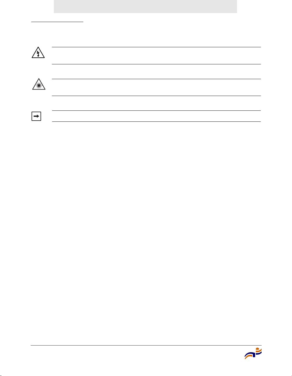
Safety and Advisory Notices
The following kinds of safety and advisory notices appear in this manual. (For
translations of the warning conventions and of all warnings in this manual, see
Appendix C, “Translated Warning Conventions and Warnings,” on page 65.)
Note. Trapeze Regulatory Information is updated frequently. See
www.trapezenetworks.com for the most current version.
Caution! This situation or condition can lead to data loss or damage to the
product or other property.
Warning! This situation or condition can cause injury.
Documentation
Chapter 1
Trapeze Mobility Point Installation Guide
Version 2.1
4
Confidential—Beta Draft—Confidential—Beta Draft—12 May 04
Text and Syntax Conventions
Trapeze manuals use the following text and syntax conventions:
Warning! High voltage. This situation or condition can cause injury due to
electric shock.
Warning! Radiation. This situation or condition can cause injury due to
improper handling of fiber-optic equipment.
Note. This information is of special interest.
Convention Use
Monospace text Sets off command syntax or sample commands and
system responses.
Bold text Highlights commands that you enter or items you
select.
Italic text Designates command variables that you replace
with appropriate values, or highlights publication
titles or words requiring special emphasis.
Menu Name > Command Indicates a menu item that you select. For example,
File > New indicates that you select New from the
File menu.
[ ] (square brackets) Enclose optional parameters in command syntax.
{ } (curly brackets) Enclose mandatory parameters in command syntax.
| (vertical bar) Separates mutually exclusive options in command
syntax.

MP Overview
5
Confidential—Beta Draft—Confidential—Beta Draft—12 May 04
2
MP Overview
A Trapeze Networks Mobility Point (MP) access point provides IEEE 802.11
wireless access to the network. MP access points are designed for use with a
Trapeze Networks Mobility Exchange (MX) switch. MP access points require
hardware installation only. All configuration for an MP access point takes place
on the MX switch.
MP Model Numbers
The MP access point models differ based on the number of 802.11 radios they
contain. Table 1 lists the MP access point model numbers.
MP Model Numbers . . . . . . . . . . . . . . . . . . . . . . . . . . . . . . . . . . . . . . . . . . . . . 5
External Hardware Features . . . . . . . . . . . . . . . . . . . . . . . . . . . . . . . . . . . . . . . 7
Connection Options . . . . . . . . . . . . . . . . . . . . . . . . . . . . . . . . . . . . . . . . . . . . . 13
Warning! Installation must be performed by qualified service personnel only.
Read and follow all warning notices and instructions marked on the product or
included in the documentation. Before installing the product, read the Trapeze
Regulatory Information document. (For translations of this warning, see
“Qualified Service Personnel Warning” on page 67.)

MP Model Numbers
Chapter 2
Trapeze Mobility Point Installation Guide
Version 2.1
6
Confidential—Beta Draft—Confidential—Beta Draft—12 May 04
The model number is listed on the product label, located to the right of the cable
ports on the bottom of the device.
Table 1. MP Access Point Model Numbers
Model Radios
MP-262 One 802.11a radio and one 802.11b/g radio. The 802.11a radio
has an internal omnidirectional antenna and the 802.11b/g
radio uses an external sectorized antenna, which must be
ordered and installed separately.
MP-252 One 802.11a radio and one 802.11b/g radio. Both radios have
internal omnidirectional antennas.
MP-241 One radio that can be configured through software for 802.11a
or 802.11b/g. The radio has an internal omnidirectional
antenna.
MP-52 One 802.11a radio and one 802.11b/g radio. Both radios have
sectorized external antennas that are adjustable and are
installed at the factory.
MP-122
(discontinued—
order MP-252)
One 802.11a radio and one 802.11b radio. Both radios have
internal omnidirectional antennas.
MP-101
(discontinued—
order MP-241)
One radio that can be configured through software for 802.11a
or 802.11b. The radio has an internal omnidirectional antenna.
Note. The MP access point radios are disabled by default and can be enabled
only by a system administrator using the MX switch.
External Hardware Features
Chapter 2
MP Overview
7
Confidential—Beta Draft—Confidential—Beta Draft—12 May 04
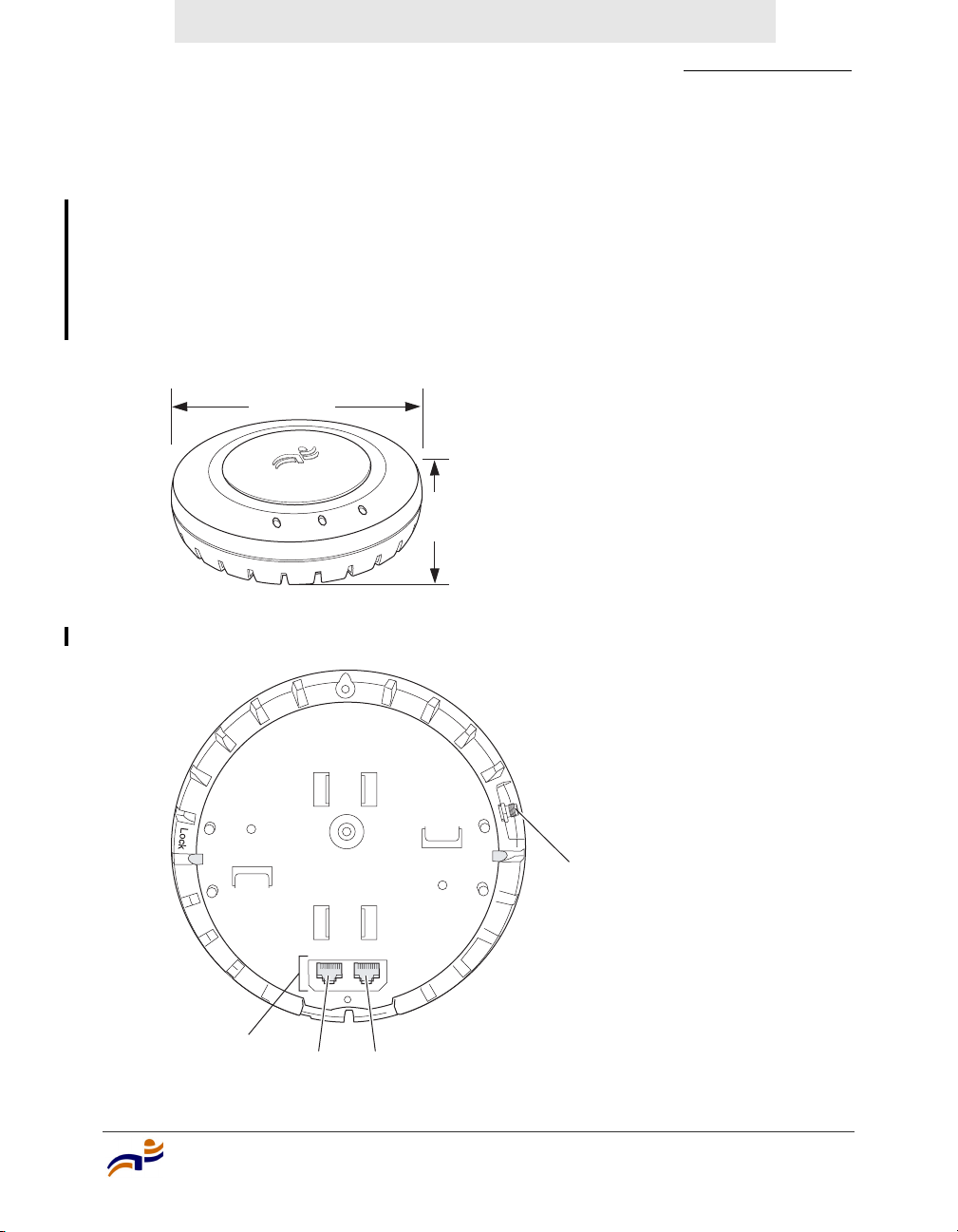
External Hardware Features
Figure 1 and Figure 2 show the external hardware features of MP access point
models MP-241, MP-252, and MP-262. All features except the external antenna
connector are the same on each model. The external antenna connector is on
model MP-262 only.
Figure 1. MP Access Point Model MP-2xx—Top View
Figure 2. MP Access Point Model MP-2xx—Bottom View
840-9502-0040
Diameter
16.76 cm
(6.6 inches)
Height
4.69 cm
(1.85 inches)
External antenna
connector (MP-262 only)
840-9502-0007
Unlock
RJ-45
ports Port 2 Port 1

External Hardware Features
Chapter 2
Trapeze Mobility Point Installation Guide
Version 2.1
8
Confidential—Beta Draft—Confidential—Beta Draft—12 May 04
Cable Ports
MP access point models MP-241, MP-252, and MP-262 have two RJ-45 ports.
(See Figure 2.) Each port provides a 10/100BASE-TX Ethernet connection to an
MX switch. The connection can be direct to an MX-switch or indirect through an
intermediate Layer 2 or Layer network.
The MP receives power and data through the ports. Use a Category 5 (Cat 5) cable
with straight-through signaling and standard RJ-45 connectors to connect the MP
access point to an MX switch or other device in the network.
The two RJ-45 ports support dual-homed configurations for redundancy. An MP
uses only one link for booting, configuration, and data transfer. If the link
becomes unavailable, the MP can reboot using the other link.
The ports are identical except for logical numbering (1 or 2). You can use either
port to connect an MP access point to an MX switch. However, an MP always
attempts to boot on MP port 1 first. Only if the boot attempt on port 1 fails does
the MP attempt to boot on port 2.
If both ports are directly connected to MX switch ports supplying Power over
Ethernet (PoE), the ports load-share. If one port becomes unavailable, the other
port can provide full power to the MP.
MP model MP-52 has one RJ-45 port for direct or indirect connection to an MX
switch.
External Antenna Connector
Model MP-262 has a connector for attaching an external sectorized antenna for
the 802.11b/g radio. (See Figure 2.) An external antenna is required for the
802.11b/g radio. The radio does not have an internal antenna. Table 2 lists the
MP-262 external antennas.
Note. MP access points do not support daisy-chain configurations. Do not
connect the MP access point to another MP access point.

External Hardware Features
Chapter 2
MP Overview
9
Confidential—Beta Draft—Confidential—Beta Draft—12 May 04
Figure 3 shows the antennas.
Figure 3. External Antennas—Model MP-262
The antennas come with a connector cable, mounting hardware, and installation
instructions.
Table 2. MP-262 External Antennas
Model
Beamwidth
Horizontal Vertical
A1060 60° 65°
A1120 120° 60°
A1180 180° 40°
Note. The MP-262 802.11b/g radio is certified for use only with these
antennas.
Model A1060
Model A1180
Model A1120
840-9502-0077

External Hardware Features
Chapter 2
Trapeze Mobility Point Installation Guide
Version 2.1
10
Confidential—Beta Draft—Confidential—Beta Draft—12 May 04
MP Mounting Options
You can mount an MP access point on any of the following types of surfaces:
●Suspended T-bar ceiling
●Junction box
●Solid surface wall or ceiling
●Tabletop
Figure 4 shows the universal mounting bracket for MP models MP-241, MP-252,
and MP-262.
Figure 4. Universal Mounting Bracket
Note. The solid surface mounting option requires Cat 5 cable that does not
have strain relief. The other mounting options can use Cat 5 cable with or
without strain relief.
840-9502-0018
Port connector
opening
T-bar flanges
Screw holes

External Hardware Features
Chapter 2
MP Overview
11
Confidential—Beta Draft—Confidential—Beta Draft—12 May 04
Status LEDs
MP access points have LEDs that provide status information for the device.
LEDs on Models MP-241, MP-252, and MP-262
Figure 5 shows the locations of the LEDs on models MP-241, MP-252, and
MP-262. Table 3 describes the LEDs.
Figure 5. Health and Radio LEDs—MP-241, MP-252, and MP-262
On model MP-241, radio LED 1 indicates activity for the single radio. On models
MP-252 and MP-262, radio LED 1 indicates activity for the 802.11b/g or 802.11b
radio, and radio LED 2 indicates activity for the 802.11a radio.
Radio 2 LED
Health LED
Radio 1 LED
840-9502-0010

External Hardware Features
Chapter 2
Trapeze Mobility Point Installation Guide
Version 2.1
12
Confidential—Beta Draft—Confidential—Beta Draft—12 May 04
Table 3. MP Access Point LEDs—MP-241, MP-252, and MP-262
LED Appearance Meaning
Health Solid green All the following are true:
• Management link with an MX switch is
operational.
• MP access point has booted.
• MP access point has received a valid
configuration from an MX switch.
• At least one radio is enabled or is in sentry
mode.
Solid amber MP access point is waiting to receive boot
instructions and a configuration file from an MX
switch.
Slowly alternating
green and amber
MP access point is booting and receiving its
configuration file from an MX switch. After the
access point boots and receives its configuration,
this LED appearance persists until a radio is
enabled or is placed in sentry mode.
Radio 1
Radio 2
Solid green A client is associated with the radio.
Blinking green Associated client is sending or receiving traffic.
Blinking amber Non-associated client is sending or receiving
traffic.
Alternating green and
amber
Radio is unable to transmit. This state can occur
due to any of the following:
• The radio is in sentry rogue detection mode.
• Excessive radio interference in the
environment is preventing the radio from
sending beacons.
• The radio has failed.
Solid amber Radio is disabled.
Unlit No radio is present or, if a radio is present and
enabled, no clients are associated with the radio
and there is no traffic activity.

Connection Options
Chapter 2
MP Overview
13
Confidential—Beta Draft—Confidential—Beta Draft—12 May 04
Connection Options
You can connect an MP access port directly to an MX switch port or indirectly to
MX switches through an intermediate Layer 2 or Layer 3 network. In either case,
use Category 5 (CAT 5) cable with straight-through signaling for each MP
connection.
For MP models with two Ethernet ports, you can provide data link redundancy by
connecting both of its ports directly to MX switch ports or indirectly to MX
switches through the network.
For all MP models, you can provide MX management redundancy even on a
single MP Ethernet port by connecting the MP indirectly to multiple MX switches
through an intermediate Layer 2 or Layer 3 network.
Note. Install the Cat 5 cables for the MP access point at the installation site
before installing the access point itself. During installation, you will insert the
Cat 5 cable(s) into the MP port(s) before attaching the access point to the
bracket.

Connection Options
Chapter 2
Trapeze Mobility Point Installation Guide
Version 2.1
14
Confidential—Beta Draft—Confidential—Beta Draft—12 May 04
Table of contents
Other Trapeze Wireless Access Point manuals

Trapeze
Trapeze Mobility Point MP-372 User manual

Trapeze
Trapeze Mobility Point MP-620 User manual

Trapeze
Trapeze Mobility Point Series User manual

Trapeze
Trapeze Mobility Point MP-122 User manual

Trapeze
Trapeze MP-82 User manual

Trapeze
Trapeze Mobility Point MP-620 User manual

Trapeze
Trapeze Mobility Point MP-620 User manual


