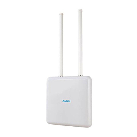
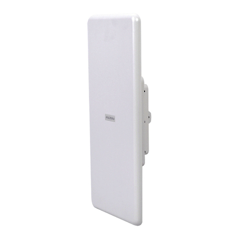
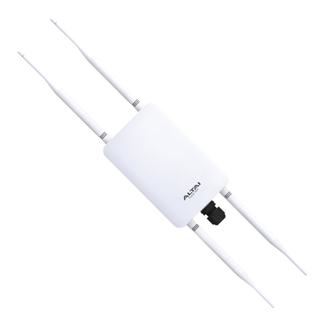
ALTAI A2 User manual

Altai Technologies Ltd. All rights reserved
ALTAI A2 WIFI ACCESS POINT/BRIDGE
INSTALLATION GUIDE
()
Version 1.0
Date: September, 2013

Altai Technologies Ltd. All rights reserved
Altai A2 WiFI Access Point/Bridge Installation Guide
TPS13-002_rev1.0
Copyright © 2007 Altai Technologies Limited
ALL RIGHTS RESERVED.
Altai Technologies Limited
Unit 209, 2/F,
East Wing, Building 17,
Hong Kong Science Park,
Shatin, New Territories,
Hong Kong
Telephone: +852 3758 6000
Fax: +852 2607 4021
Web: www.altaitechnologies.com
Customer Support Centre:
Email: supp[email protected]
Radio Frequency Interference Requirements
This device complies with Part 15 of FCC Rules.
Operation is subject to the following conditions:
1. This device may not cause harmful interference.
2. This device must accept any interference received, including interference
that may cause undesired operation.
3. This device should not be co-located or operating in conjunction with any
other antenna or transmitter.
Interference Statement
This equipment has been tested and found to comply with the limits for a Class B
digital device, pursuant to Part 15 of the FCC Rules. These limits are designed to
provide reasonable protection against harmful interference in a residential installation.

Altai Technologies Ltd. All rights reserved
Altai A2 WiFI Access Point/Bridge Installation Guide
TPS13-002_rev1.0
This equipment generates uses and can radiate radio frequency energy. If it is not
installed and used in accordance with the instructions, harmful interference to radio
communications may be caused.
However, there is no guarantee that interference will not occur in a particular
installation. If this equipment does cause harmful interference to radio or television
reception, which can be determined by turning the equipment off and on, the user is
encouraged to try to correct the interference by one of the following measures:
-Reorient or relocate the receiving antenna.
-Increase the separation between the equipment and receiver.
-Connect the equipment into an outlet on a circuit different from that
to which the receiver is connected.
-Consult the dealer or an experienced radio/TV technician for help.
FCC Caution: To assure continued compliance,(example –use only shielded
interface cables when connecting to computer or peripheral devices) any changes
or modifications not expressly approved by the party responsible for compliance
could void the user’s authority to operate this equipment.
Warning
The user is advised to keep away from the base-station and antenna with at least
45cm when the base-station is in operation.
Please install a lightning arrestor to protect the base station from lightning dissipation
during rainstorms. Lightning arrestors are mounted outside the structure and must be
grounded by means of a ground wire to the nearest ground rod or item that is
grounded.
Disclaimer
All specifications are subject to changes without prior notice. Altai Technologies
assumes no responsibilities for any inaccuracies in this document or for any obligation
to update information in this document. This document is provided for information
purposes only. Altai Technologies reserves the right to change, modify, transfer, or
otherwise revise this publication without notice.

Altai Technologies Ltd. All rights reserved
Altai A2 WiFI Access Point/Bridge Installation Guide
TPS13-002_rev1.0
Contents
1. Introduction ........................................................................................................................................... 5
2. Field Installation .................................................................................................................................... 5
2.1. Check A2 WiFi Access Point/Bridge Packages ......................................................................... 5
2.2. Introducing A2 WiFi Access Point/Bridge.................................................................................... 7
2.3. Installing A2 WiFi Access Point/Bridge ......................................................................................... 8
2.4. 2.4 Mounting A2 WiFi Access Point/Bridge ................................................................................. 8
2.5. Connecting Ethernet cable to A2 waterproofing cable protector....................................11
2.6. General Antenna and Safety Recommendations .................................................................18
2.7. 5GHz Antenna Alignment LED .................................................................................................... 19
2.8. Grounding A2 WiFi Access Point/Bridge ...................................................................................20
2.9. Surge Protection ............................................................................................................................20
2.10. ESD Protection................................................................................................................................ 21
2.11. Resetting A2 WiFi Access Point/Bridge to factory default settings......................................21
2.12. Reviewing Installation Procedures ............................................................................................. 22
3. Typical Site Setups ..............................................................................................................................22

Altai Technologies Ltd. All rights reserved
Altai A2 WiFI Access Point/Bridge Installation Guide
TPS13-002_rev1.0
1. Introduction
This document is written to provide the information needed to mount A2 WiFi Access
Point/Bridge and A2 antennas on site location.
This document is applicable for hardware platform A2 and the following models.
Product name : A2 WiFi Access Point/Bridge
Model number : AP5822
It is assumed that site survey has been performed. And appropriate antenna pole
and AP locations have been selected. Good site installation plan should consist of site
map, drawing illustrating AP and poles locations, antenna bearing/down-tilt, antenna
height and plan on network topology.
User may need to refer the following documents during A2 installation and
configuration.
[1] A2 Configuration Manual
[2] A2 WiFi Access Point/Bridge Data Sheet
2. Field Installation
2.1. Check A2 WiFi Access Point/Bridge Packages
Check the package against the packing list to ensure all equipment and necessary
parts are included. Typical shipment consists of equipment and parts as shown below.
Please contact the sales representative if there is any difference from the packing list.
Moreover, verify if the equipment has any physical defect. If so, please contact the
sales representative for repair or replacement.

Altai Technologies Ltd. All rights reserved
Altai A2 WiFI Access Point/Bridge Installation Guide
TPS13-002_rev1.0
Figure 2-1 typical A2 Package
Product:
A2 WiFi Access Point/Bridge × 1
Accessories:
Mounting Kit × 1 (Set)
One PoE Power Injector ×1
Waterproof Plug × 1 (Set)

Altai Technologies Ltd. All rights reserved
Altai A2 WiFI Access Point/Bridge Installation Guide
TPS13-002_rev1.0
Figure 2-2 Mounting Kit detail
2.2. Introducing A2 WiFi Access Point/Bridge
Figure 2-3 A2 Back View
Note:
1. Warranty will be voided if warranty labels are broken
2. Highly recommended to configure the bridge setting (e.g. the Frequency
channel, remote bridge MAC, security type) before site installation.

Altai Technologies Ltd. All rights reserved
Altai A2 WiFI Access Point/Bridge Installation Guide
TPS13-002_rev1.0
2.3. Installing A2 WiFi Access Point/Bridge
Before site installation, please prepare the following tools and accessories:
Tools:
1) Screw Driver
2) Sealing Tape
Accessories
1) Grounding Kit × 1
2) Ethernet Cable × 2
3) Waterproof Seal
2.4. 2.4 Mounting A2 WiFi Access Point/Bridge
1. Install the mounting bracket at the back of A2 WiFi Access Point/Bridge
2. Fix A2 WiFi Access Point/Bridge relevant the real situation
(a) Fix the mounting bracket on the pole using hose clamps.
Figure 2-4 A2 main unit on the mounting bracket

Altai Technologies Ltd. All rights reserved
Altai A2 WiFI Access Point/Bridge Installation Guide
TPS13-002_rev1.0
Figure 2-5 Mount the bracket on the pole
(b) Fasten A2 main unit on the wall with the mounting bracket and bolt
Figure 2-6 Mount the bracket on the wall

Altai Technologies Ltd. All rights reserved
Altai A2 WiFI Access Point/Bridge Installation Guide
TPS13-002_rev1.0
1. (A2 AP Mode) Install a pair of omni-directional antennas to A2 WiFi Access
Point/Bridge RF ports, and properly seal the connections with waterproof
sealing tape. A typical waterproof sealing tape is shown in 错误!未找到引用
源。8.
2. Connect Ethernet cables
An Ethernet cable must be connected between the A2 Ethernet port
and the Power over Ethernet (PoE) Output port. The PoE AC Adapter
supplies the power to A2.
Another Ethernet cable (RJ –45 Straight Cable) must be connected
between the PoE Input Port and the computer or backhaul link.
PoE Port
Connect to
Input
Backhaul link, computer or peripherals
Output
A2 Ethernet port
Table 2-1 Summary of PoE connections
Figure 2-7 Connections of the PoE

Altai Technologies Ltd. All rights reserved
Altai A2 WiFI Access Point/Bridge Installation Guide
TPS13-002_rev1.0
Figure 2-8 3M Scotch 130C
Caution: Make sure cables are connect to correct ports of the PoE to avoid
electrical damage to peripheral Ethernet port!
2.5. Connecting Ethernet cable to A2 waterproofing
cable protector
1. Depends on deployment site requirements, CAT5e (or above) Ethernet cable with
appropriate length (maximum 100m) should be prepared before A2 installation.
Please check the waterproof plug set as shown in the figure below.
Figure 2-9 Waterproof Plug Set

Altai Technologies Ltd. All rights reserved
Altai A2 WiFI Access Point/Bridge Installation Guide
TPS13-002_rev1.0
2. Mount the housing and screw nut as picture below
Figure 2-10 Mount the housing and screw nut
3. Put the seals in the housing.
Figure 2-11 Put the seals in the housing

Altai Technologies Ltd. All rights reserved
Altai A2 WiFI Access Point/Bridge Installation Guide
TPS13-002_rev1.0
4. Put the seals in the housing in to the Ethernet connector parts as the sequence
denote in the pictures.
Figure 2-12 Insert the cable
Figure 2-13 Connect together
5. Use wire stripping tool to remove Ethernet cable jacket. Pull the sticker off from the
gasket of the Ethernet plug and paste it to housing through the Ethernet cable.

Altai Technologies Ltd. All rights reserved
Altai A2 WiFI Access Point/Bridge Installation Guide
TPS13-002_rev1.0
Figure 2-14 Pull the sticker off
Figure 2-15 Strip the jacket of cable and paste the gasket
6. At the end of cable, RJ-45 modular pins should be numbered 1 through 8 as
shown below:
Figure 2-16 Pin Position

Altai Technologies Ltd. All rights reserved
Altai A2 WiFI Access Point/Bridge Installation Guide
TPS13-002_rev1.0
The assignments of wire pairs to plug and jack pins are as follow:
Pin
Pair
wire Color
1
2
white/orange stripe
2
2
orange solid
3
3
white/green stripe
4
1
blue solid
5
1
white/blue stripe
6
3
green solid
7
4
white/brown stripe
8
4
brown solid
Table 2-2 Cable wire pairs
Caution: Recommended proper sealing to outdoor connector. Proper sealing
prevent water ingress to it and protect it from gradual degradation due to UV
radiation and pollution.

Altai Technologies Ltd. All rights reserved
Altai A2 WiFI Access Point/Bridge Installation Guide
TPS13-002_rev1.0
Figure 2-17 Cable modular and connection to A2

Altai Technologies Ltd. All rights reserved
Altai A2 WiFI Access Point/Bridge Installation Guide
TPS13-002_rev1.0
7. Ethernet cable waterproof protection
1) Start wrapping a layer of electrical tape from 2” (50mm) below the edge of
the cable connector. Overlap the tape to half –width. The tape should cover
the cable connector body and the cable connector clamping nut.
2) The tape can be applied in one or more strips if necessary. A strip can be
coiled onto an applicator such as a pencil. Apply only enough tension to get
good adhesion and keep the tape smooth.
3) Start wrapping a layer of butyl rubber tape from 1” (25mm) below the edge
of the cable connector. Overlap the tape to half –width. Take extra care to
make sure that the cable connector-A2 Ethernet port junction is tightly
sealed. Press the tape edges together so that there are no gaps. Press the
tape against the cable connector body and the Ethernet port.
4) Start wrapping a layer of electrical tape from 1” (25mm) below the edge of
the cable connector. Overlap the tape to half –width.
Figure 2-18 Ethernet cable waterproof protection
8. (Optional) Unused RF Ports Waterproof Protection

Altai Technologies Ltd. All rights reserved
Altai A2 WiFI Access Point/Bridge Installation Guide
TPS13-002_rev1.0
Figure 2-19 Unused RF Ports Waterproof Protection
1. For both unused RF ports, retain the RF caps on the ports.
2. Start wrapping a layer of butyl rubber tape from the bottom of RF port. Overlap
the tape to half –width. Take extra care to make sure that the RF port and the RF
cap are tightly sealed by the tape. Press the tape edges together so that there
are no gaps.
3. Start wrapping a layer of electrical tape the base of the RF port. Overlap the
tape to half –width.
2.6. General Antenna and Safety Recommendations
Please follow these safety recommendations while installing an antenna:
For safety reasons, never touch a high-gain antenna or point it at any part
of your body when it is in operation.
Follow the instructions come with your antenna manual.
Keep antennas away from metal objects and obstructions (heating and air-
conditioning ducts, large ceiling trusses, building superstructures, and major
power cabling runs).
Utilize built-in +16dBi patch antenna to establish a link between two
buildings.
Locate a pair of omni-directional antenna in the middle of the desired
coverage area if possible.
Outdoor antennas should be mounted at a sufficient height to prevent the
radio path from being blocked by obstructions such as trees and buildings.
Antenna towers should keep a safe distance from overhead power lines.
Recommended twice distance of the tower height.
Use proper ground kits and follow national safety regulation to properly
ground outdoor antenna and tower.
Ensure proper sealing on antenna cable and all external cable connecter
using waterproofing product (e.g.: coax compatible electrical tape and
coax-seal) to prevent water ingress.

Altai Technologies Ltd. All rights reserved
Altai A2 WiFI Access Point/Bridge Installation Guide
TPS13-002_rev1.0
2.7. 5GHz Antenna Alignment LED
When A2 WiFi Access Point/Bridge utilizes the built-in +16dBi patch antenna to
establish a bridge, then antenna should be aligned manually. Both vertical and
horizontal beamwidth of built-in +16dBi patch antenna are approximately between
25 to 30 degrees.
A2 can be configured to show the signal strength using two LED lights.
When the signal is weak, the lower light will be off. When the signal strength exceeds
the highest level configured in the web interface, the lower light will be solid on.
When the signal strength is intermediate, the lower light will blink about every five
seconds.
Figure 2-20 Signal strength indicator: Strong (left) and Weak (right)
Upper light
Lower light
Signal strength
ON
OFF
Weak
ON
Blink periodically
Intermediate
ON
Solid ON
Strong
Table 2-3 Summary of lights indication

Altai Technologies Ltd. All rights reserved
Altai A2 WiFI Access Point/Bridge Installation Guide
TPS13-002_rev1.0
2.8. Grounding A2 WiFi Access Point/Bridge
It is essential to properly ground all equipment to prevent the A2 from the electrical
damage and possible electric hazer due to non-proper power grounding. Use a
10AWG grounding wire to connect to the ground connector of the A2 WiFi Access
Point/Bridge by screw driver. Secure the grounding screw tight and the strap
connects to the ground (Please refer to 错误!未找到引用源。3 for the position of
Grounding point of A2).
It is recommended that the A2 WiFi Access Point/Bridge should be installed with
lightning rod to avoid any potential electrical damage and to be connected with the
ground node to the existing ground. Proper grounding will always be the safety
consideration for the A2 WiFi Access Point/Bridge.
Note: Grounding kits are not provided in the package.
2.9. Surge Protection
The type of Ethernet cable to be used in outdoor deployment is critical. The Ethernet
cable should be either CAT5 or CAT5e, outdoor rated, and shielded. Specifically, the
following types of Ethernet cable should be used for outdoor installation: sFTP, FTP, or
STP.
Using UTP Ethernet cable and / or unshield RJ-45 jack are not recommended due
to the increased electromagnetic noise level for outdoor deployment. Furthermore,
using shielded CAT5 Ethernet cable without using shielded RJ45 jack at the base
station and PoE injector may cause more problems than not using it. This is because if
a shielded CAT5 Ethernet is ungrounded, it will act as a magnet for static charges
present in the environment. Since the charges cannot be discharged properly
through a shielded RJ45 jack, it may couple with the internal data or power lines of
the PoE cable. As a result, the coupling of high voltages present on the Ethernet
cable may damage the base station directly interfacing with it. Therefore, it is
important to always use shielded outdoor rated Ethernet cable together with shielded
RJ45 jack in outdoor deployment.
The only difference between crimping an UTP cable and a FTP cable is that the
latter has a small wire under the foil. This wire (preferably 2cm longer than other wires),
also known as the drain wire, should be wrapped around the outside of the shield
when installing the shielded RJ45 plug. It is very important to have direct contact
between the foil and the shield of the RJ45 connector.
The following figure shows a shielded, metal-enclosed RJ45 connector. First the
boot is slid onto the cable, then the cable shield and drain wire are folded back, next
the load bar is loaded with the eight inner cable conductors, then the load
Other manuals for A2
1
Table of contents
Other ALTAI Wireless Access Point manuals
Popular Wireless Access Point manuals by other brands

Siemens
Siemens SIMATIC NET SCALANCE W M763-1 Series Reference manual

Cabletron Systems
Cabletron Systems RoamAbout user guide

Intermec
Intermec MobileLAN access 2106 quick start guide

Linksys
Linksys WAP55AG - Wireless A+G Access Point user guide

Shure
Shure AXT610 ShowLink user manual

Abocom
Abocom 802.11g Wireless Access Point WAP253 Quick install guide