Traxon Media Tube Plus User manual
Media Tube®Plus
INSTALLATION GUIDE V1.0
www.traxon-ecue.com ©2023 TRAXON TECHNOLOGIES. ALL RIGHTS RESERVED.
Installation Guide 02/23 V1.0 2 of 21
Content
1. Safety And Operation 3
2. Introduction 4
3. Installation 9
4. System Conguration 13
5. Care and Maintenance 18
6. Technical Specication 19
7. Troubleshooting 20
8. Warranty Statement 20
For your own safety and that of the product, please read this installation guide carefully before
beginning setup and installation.

www.traxon-ecue.com ©2023 TRAXON TECHNOLOGIES. ALL RIGHTS RESERVED.
Installation Guide 02/23 V1.0 3 of 21
1. Safety And Operation
1. CAUTION - Unplug the power supply from the mains power before connecting any cables as this
can damage the products.
2. CAUTION - Avoid looking directly into the LED light source at close range for your own safety.
3. Persons installing this product should make sure:
a. The installation complies with all applicable codes, state and local laws, ordinances, standards
and safety regulations.
b. The installation environment is carefully studied and suitable surge protection measure(s) is
taken.
c. He or she is qualied for the handling of electrical equipment.
4. Do not attempt to install or use the product until installation instructions and safety labels are fully
understood. This product is designed for indoor and outdoor use.
5. Ensure product operates within the specied temperature range. (Refer to “6. Technical
Specication” on page 19 for more details.)
6. Do not attempt to open the product. Not user serviceable.
7. Do not use the product if any part of it, or the power cables are damaged.
8. Only use product for specied voltage, do not exceed. (Refer to “6. Technical Specication” on
page 19 for more details.)
9. Always maintain connection to ensure waterproong.
10. If the product has been subjected to drastic temperature variances, for example, following
transportation, do not connect the xture until it has reached room temperature, as moisture
condensation may cause electric shock and product damages.
11. When installing the products and system power supplies, please ensure they will not be exposed
to moisture and extreme heat (and direct sunlight for outdoor products). Besides, keep a clean
operating environment for the xtures and system power supplies.
12. Please study this Installation Guide thoroughly and check the latest Technical Specication Sheets
available from the Traxon website www.traxon-ecue.com before setup.
13. Any non-compliance of the Installation Guide will void the Traxon warranty.
Please read through Safety and Operation before start of the installation.

www.traxon-ecue.com ©2023 TRAXON TECHNOLOGIES. ALL RIGHTS RESERVED.
Installation Guide 02/23 V1.0 4 of 21
2. Introduction
2.1 General
Media Tube® Plus is a slim, direct view luminaire designed to integrate into any wall, facade or media lighting application
with tight installation requirements. Available with a Direct View or Diffused View lens and 9 pixels per 300mm / 1’,
Media Tube®Plus provides smooth effects to add life and motion to the installation. Featuring Auto-Addressing and
simple quick-lock connections, Media Tube®Plus is perfect for building façades, media applications, and more.
Features:
—Available lengths: 296mm / 1ft (9PXL), 596mm / 2ft (18PXL), 896mm / 3ft (27PXL), 1196mm / 4ft (36PXL) and
1496mm / 5ft (45PXL)
—Diused view and direct view, two color options: RGBW, RGB
—e:pix / DMX512
—Daisy Chain System with quick lock connectors
—Auto-Addressing per daisy-chain (by default) or manual-addressing with TX addresser
—IP66, Suitable for Coastal Environment, IK09 (Diused View) and 3G Vibration Resistant
Media Tube®Plus Direct View Length Maximum number of pixels (PXL)
MEDIA TUBE PLUS RGBW 1496 45P CLEAR 1496mm / 58.9” 45
MEDIA TUBE PLUS RGBW 1196 36P CLEAR 1196mm / 47.09” 36
MEDIA TUBE PLUS RGBW 896 27P CLEAR 896mm / 35.28” 27
MEDIA TUBE PLUS RGBW 596 18P CLEAR 596 mm / 23.46” 18
MEDIA TUBE PLUS RGBW 296 9P CLEAR 296mm / 11.65” 9
MEDIA TUBE PLUS RGB 1496 45P CLEAR 1496mm / 58.9” 45
MEDIA TUBE PLUS RGB 1196 36P CLEAR 1196mm / 47.09” 36
MEDIA TUBE PLUS RGB 896 27P CLEAR 896mm / 35.28” 27
MEDIA TUBE PLUS RGB 596 18P CLEAR 596mm / 23.46” 18
MEDIA TUBE PLUS RGB 296 9P CLEAR 296mm / 11.65” 9
Media Tube® Plus Diused View Length Maximum number of pixels (PXL)
MEDIA TUBE PLUS RGBW 1496 45P DIFFUSED 1496mm / 58.9” 45
MEDIA TUBE PLUS RGBW 1196 36P DIFFUSED 1196mm / 47.09” 36
MEDIA TUBE PLUS RGBW 896 27P DIFFUSED 896mm / 35.28” 27
MEDIA TUBE PLUS RGBW 596 18P DIFFUSED 596mm / 23.46” 18
MEDIA TUBE PLUS RGBW 296 9P DIFFUSED 296mm / 11.65” 9
MEDIA TUBE PLUS RGB 1496 45P DIFFUSED 1496mm / 58.9” 45
MEDIA TUBE PLUS RGB 1196 36P DIFFUSED 1196mm / 47.09” 36
MEDIA TUBE PLUS RGB 896 27P DIFFUSED 896mm / 35.28” 27
MEDIA TUBE PLUS RGB 596 18P DIFFUSED 596mm / 23.46” 18
MEDIA TUBE PLUS RGB 296 9P DIFFUSED 296mm / 11.65” 9
www.traxon-ecue.com ©2023 TRAXON TECHNOLOGIES. ALL RIGHTS RESERVED.
Installation Guide 02/23 V1.0 5 of 21
2.2 Dimensions
FIG.1: Media Tube®Plus Direct View
L
296mm/11.65”
40mm/
1.57”
140mm/5.51“
30mm/
1.18”
30mm/
1.18”
140mm/5.51“
H1
H2
W1
W2
W1 W2 H1 H2 L
1496mm / 59” 24.5mm / 0.96” 33.7mm / 1.33” 63mm / 2.48” 35mm / 1.38” 1496mm / 58.90”
1196mm / 47” 24.5mm / 0.96” 33.7mm / 1.33” 63mm / 2.48” 35mm / 1.38” 1196mm / 47.09”
896mm / 35” 24.5mm / 0.96” 33.7mm / 1.33” 63mm / 2.48” 35mm / 1.38” 896mm / 35.28”
596mm / 23” 24.5mm / 0.96” 33.7mm / 1.33” 63mm / 2.48” 35mm / 1.38” 596mm / 23.46”
296mm / 12” 24.5mm / 0.96” 33.7mm / 1.33” 63mm / 2.48” 35mm / 1.38” 296mm / 11.65”
NOTE: Please see CAD les for additional dimensional data.
www.traxon-ecue.com ©2023 TRAXON TECHNOLOGIES. ALL RIGHTS RESERVED.
Installation Guide 02/23 V1.0 6 of 21
FIG.2: Media Tube® Plus Diused View
L
296mm/11.65”
40mm/
1.57”
140mm/5.51“
30mm/
1.18”
30mm/
1.18”
140mm/5.51“
H1
H2
W1
W2
W1 W2 H1 H2 L
1496mm / 59” 24.5mm / 0.96” 33.7mm / 1.33” 78mm / 3.07” 50mm / 1.97” 1496mm / 58.90”
1196mm / 47” 24.5mm / 0.96” 33.7mm / 1.33” 78mm / 3.07” 50mm / 1.97” 1196mm / 47.09”
896mm / 35” 24.5mm / 0.96” 33.7mm / 1.33” 78mm / 3.07” 50mm / 1.97” 896mm / 35.28”
596mm / 23” 24.5mm / 0.96” 33.7mm / 1.33” 78mm / 3.07” 50mm / 1.97” 596mm / 23.46”
296mm / 12” 24.5mm / 0.96” 33.7mm / 1.33” 78mm / 3.07” 50mm / 1.97” 296mm / 11.65”
NOTE: Please see CAD les for additional dimensional data.
www.traxon-ecue.com ©2023 TRAXON TECHNOLOGIES. ALL RIGHTS RESERVED.
Installation Guide 02/23 V1.0 7 of 21
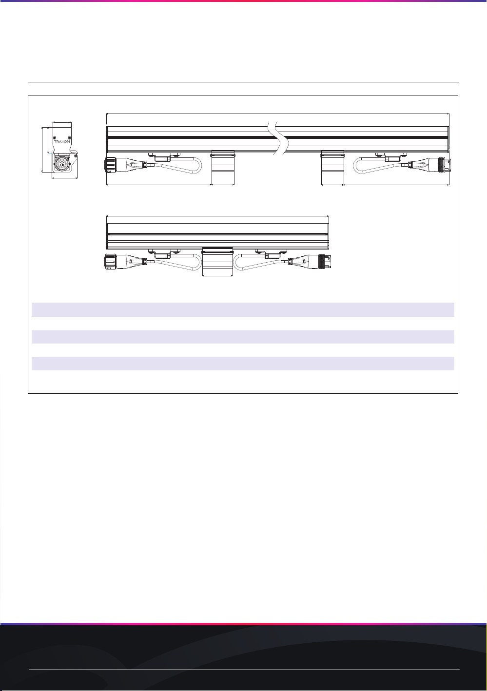
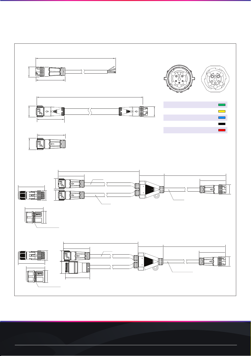
FIG.3: Media Tube®Plus Accessories
End Cap with 120 Ohm Terminator
Starter Cable
Interconnection Cable
End Cap with 120 Ohm Terminator
Starter Cable
Interconnection Cable
End Cap with 120 Ohm Terminator
Starter Cable
Interconnection Cable
1m, 5m, 30m / 3.28’, 16.40’, 98.43”
0.14m, 1m, 4m / 0.46’, 3.28’, 13.12’
56.3mm / 2.22”
2*17AWG+3*24AWG
Round Cable
22.5mm / 0.89” 22.5mm / 0.89” 20.3mm / 0.80”
20.3mm
2*17AWG+3*24AWG
12mm*4mm / 0.47”*0.16” Flat Cable
56.3mm / 2.22”
Power Injector Cable Kit (Connector included)
RJ45 Power Injector Cable Kit (Connector included)
150mm/5.91”
57mm/2.24”
22.5mm/0.89”
56.3mm/2.22”
22.5mm/0.89”
57mm/2.24”
20.3mm/0.8”
PVC Cable Black 2X17AWG+3X24AWG
150mm/5.91”
UL Rubber Cable Black 2*16AWG
56.3mm/2.22”
20.3mm/0.8”
150mm/5.91”
56.3mm/2.22”
20.3mm/0.8”
UL Rubber Cable Black 2*16AWG
150mm/5.91”
57mm/2.24”
∅
25.8mm/1.02”
39.6mm/1.57”
52.2mm/2.06”
56.3mm/2.22”
22.5mm/0.89”
20.3mm/0.8”
57mm/2.24”
26.2mm/1.03”
PVC Cable Black 2X17AWG+3X24AWG
Waterproof cap
PVC Cable Black 2X17AWG+3X24AWG
∅
25.8mm/1.02”
39.6mm/1.57”
Waterproof cap
NOTE: Please see CAD les for additional dimensional data.
Wire# Description Color
1Data+ Green
2Address Yellow
3Data− Blue
4DC48V− Black
5DC48V+ Red
Connector Pin Assignment
Yellow
Green
Blue
Black Red Red Black
Green Blue
Yellow
1
2
3
45
12
3
45
Input
Yellow
Green
Blue
Black Red Red Black
Green Blue
Yellow
1
2
3
45
12
3
45
Output
www.traxon-ecue.com ©2023 TRAXON TECHNOLOGIES. ALL RIGHTS RESERVED.
Installation Guide 02/23 V1.0 8 of 21
2.3 Packing Contents
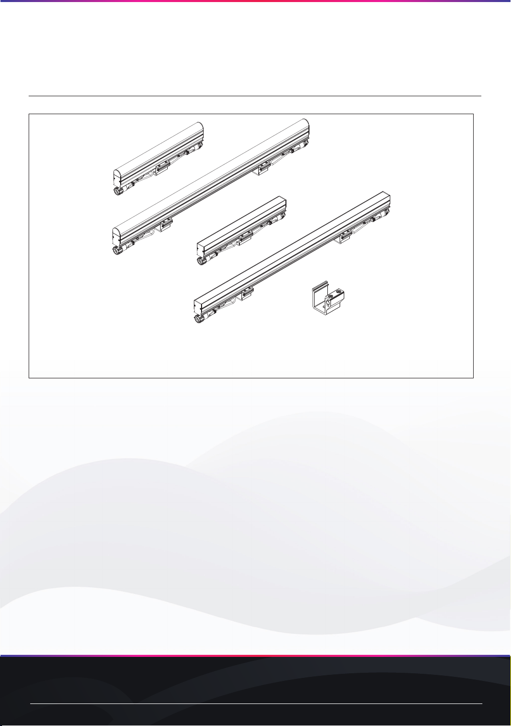
FIG.4: Media Tube® Plus Packing Contents
Media Tube®Plus Direct/Diffused View
Mounting bracket:
x1 bracket for 296mm/12” fixture
x2 brackets for other length fixtures
www.traxon-ecue.com ©2023 TRAXON TECHNOLOGIES. ALL RIGHTS RESERVED.
Installation Guide 02/23 V1.0 9 of 21
3. Installation
3.1 Points To Consider
Plan your installation before mounting the Media Tube® Plus. The following should be considered for a
successful installation.
—Weather conditions and ambient temperature of installation site.
—Appropriate cable lengths (cable gauges described in system diagram). Please consult your local
Traxon oce or authorized agent for necessary aid.
—The number of the Media Tube® Plus and appropriate LED Engines.
—e:pix / DMX512 to be used to control the Media Tube®Plus.
—Distance between each Tube for thermal expansion and maintaining pixel pitch.
—Mounting distances should be considered.
—Proper surge protection.
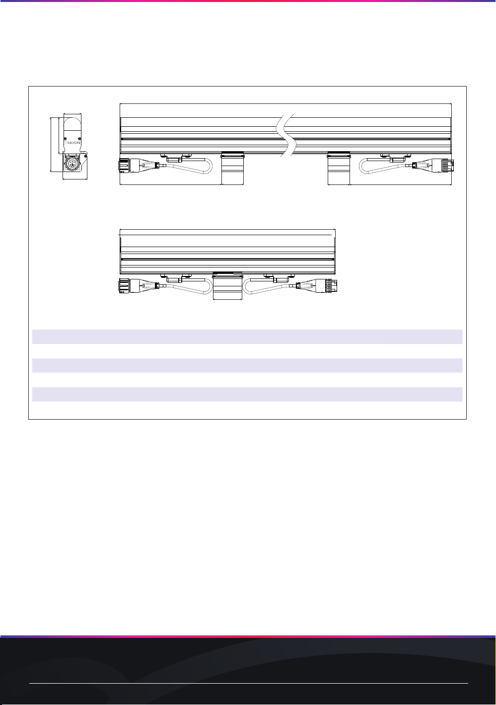
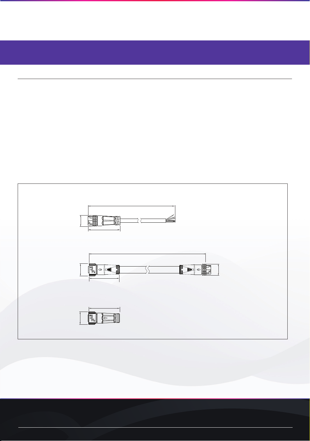
FIG.5: Media Tube®Plus Cable System
Starter Cable
From terminal block to rst Media Tube®Plus in chain
Interconnection Cable
From Media Tube®Plus to another Media Tube®Plus
End Cap with 120Ω Terminator
The end cap includes e:pix / DMX data terminator
End Cap with 120 Ohm Terminator
Starter Cable
Interconnection Cable
1m, 5m, 30m / 3.28’, 16.40’, 98.43”
2*18AWG+4*24AWG
Round Cable
20.3mm / 0.80”
φ6.5mm / 0.26”
End Cap with 120 Ohm Terminator
Starter Cable
Interconnection Cable
0.14m, 1m, 4m / 0.46’, 3.28’, 13.12’
22.5mm / 0.89”
20.3mm / 0.8”
2*17AWG+3*24AWG
12mm*4mm / 0.47”*0.16” Flat Cable
End Cap with 120 Ohm Terminator
Starter Cable
Interconnection Cable
56.3mm / 2.22”
22.5mm / 0.89”

www.traxon-ecue.com ©2023 TRAXON TECHNOLOGIES. ALL RIGHTS RESERVED.
Installation Guide 02/23 V1.0 10 of 21
3.2 Pre-Installation Checks
3.2.1 Installation Checklist
1. Prepare cables and all necessary accessories (Waterproof Quick Lock End Caps etc).
2. Perform functional check of the Media Tube® Plus. Take care not to damage cables/connectors
during pre-installation checks.
3. Ensure all pre-installation checks laid out below have been followed.
4. Mount the Media Tube® Plus on-site. If the installation is to be left uncompleted overnight, place all
non-connected LED Engines and the Media Tube®Plus in an indoor environment.
5. All units must be connected or utilize end caps to protect from water ingress.
Ensure all the Interconnection Cables, Media Tube® Plus and LED Engines are initially stored in a dry
area to guarantee the complete sealing of the system from water before installation.
3.2.2 Mounting Bracket
Mounting hardware (screws, lock washers and washers) are required for mounting the bracket to the
surface. Mounting hardware by others. The mounting brackets can be moved along the extrusion to
match installation requirements.
FIG.6: Mounting Bracket
x1 bracket for 296mm/12” fixture
x2 brackets for other length fixtures
Tighten screw to lock
bracket in place
Mounting Hardware
(By others)
3.2.3 Installation Sequence
1. Measure the correct distances for brackets and install the Media Tube® Plus xtures.
2. Connect the Media Tube® Plus in the daisy-chain manner outlined in the System Diagram.
3. Perform functional check on all the Media Tube®Plus and inspect cables and brackets for any
damage. Check for any abnormalities with the control signal.
4. Report any functional defect found to your nearest Traxon Technologies oce. DO NOT attempt
to install the Media Tube®Plus with functional defects on-site.
www.traxon-ecue.com ©2023 TRAXON TECHNOLOGIES. ALL RIGHTS RESERVED.
Installation Guide 02/23 V1.0 11 of 21
3.3 On-Site Installation
— DO NOT attempt installation in wet or severe weather conditions.
— DO NOT leave and expose any Media Tube® Plus or LED Engines unconnected
under wet/raining or snowing environment.
— IP failure induced by stressed/damaged cables during or after installation will not
be under warranty.
— ALWAYS keep the cables protected from sharp objects and ensure no damage is
generated on the cable.
— Failure to keep Media Tube® Plus within the operating temperature range of
–40°C to +60°C / –40°F to +140°F and storage temperature range of –40°C to
+80°C / –40°F to +176°F will void the product’s warranty.
3.3.1 On-Site Installation
1. Fix brackets to installation surface with anchor bolts or screws (by others).
2. The Media Tube® Plus are interconnected using the IN and OUT cables/connectors on each end
of the tube. Connectors will make an audible “click” when connected. Gently pull on the cables in
opposites directions to ensure they are fully locked and do not come loose. The below diagram
shows the Tube connections. Always remember to ax a Quick Lock Waterproof End Cap (sold
separately) for the OUT connector of the nal Tube in each daisy chain. See System Diagram for
details.
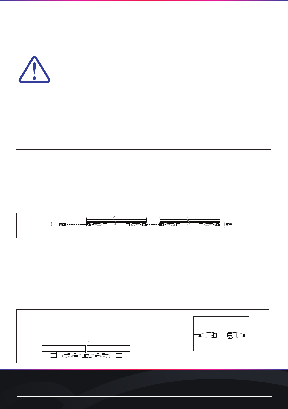
FIG.7: Media Tube®Plus Connections
Starter Cable End Cap
NOTE: Any water ingress incurred due to improper installation of cable connectors or Waterproof
Quick Lock End Caps will not be covered under warranty.
3. Be sure not to compress the IN/OUT cables.
NOTE: To keep LED pitch consistent and allow for thermal expansion, be sure to keep a minimum
distance of 1.5mm / 0.06” (direct view) or 4mm / 0.16” (diused view) between consecutive Media
Tube®Plus (see below diagram).
FIG.8: Keep minimum distance between xtures
To maintain consistent LED pitch and to allow for thermal expansion for Tubes:
End Cap Seal on Last Tube
The minimum distance depends on the temperature difference.
Normally, it is 1.5mm/0.06” (direct view) or 4mm/0.16” (diffused view).
When the temperature difference is greater than 35oC/95oF, 5mm/0.2” is needed.
Max. distance: 100mm/3.94”
Min. or Max. distance

www.traxon-ecue.com ©2023 TRAXON TECHNOLOGIES. ALL RIGHTS RESERVED.
Installation Guide 02/23 V1.0 12 of 21
4. The rst tube of the daisy-chain group has to be connected to the control system via Waterproof
Junction Box (by others). Starter cables, Data and Power cables, and video ber optic cables have
to be installed through conduit.
5. Set up the control system indoors as detailed in the system diagram and connect to the Media
Tube®Plus.
6. Start each unit and verify correct function.

www.traxon-ecue.com ©2023 TRAXON TECHNOLOGIES. ALL RIGHTS RESERVED.
Installation Guide 02/23 V1.0 13 of 21
4. System Conguration
4.1 Pixel Control
The LEDs on the Media Tube®Plus are controlled by e:pix / DMX512. For RGBW, each pixel on the
Tube uses two RGB 3 in 1 LED and 1 white LEDs, for R, G, B and W channels. Pixel number 1 begins
on the IN connector side, and it uses the rst four channels. RGB works in a similar way, but use less
pixels per length.
2 RGB 3 in 1 LEDs and 1 White LED
2 RGB LEDs
6 DW LEDs
Media Tube®Plus RGBW
Pixel n Control Channel Number
R+4(n-1) + 1
G+4(n-1) + 2
B +4(n-1) + 3
W+4(n-1) + 4
Where: n is pixel number along the Tube.
(Pixel 1 is located near the IN connector.)
2 RGB 3 in 1 LEDs and 1 White LED
2 RGB LEDs
6 DW LEDs
Media Tube®Plus RGB
Pixel n Control Channel Number
R+3(n-1) + 1
G+3(n-1) + 2
B +3(n-1) + 3
Where: n is pixel number along the Tube.
(Pixel 1 is located near the IN connector.)
www.traxon-ecue.com ©2023 TRAXON TECHNOLOGIES. ALL RIGHTS RESERVED.
Installation Guide 02/23 V1.0 14 of 21
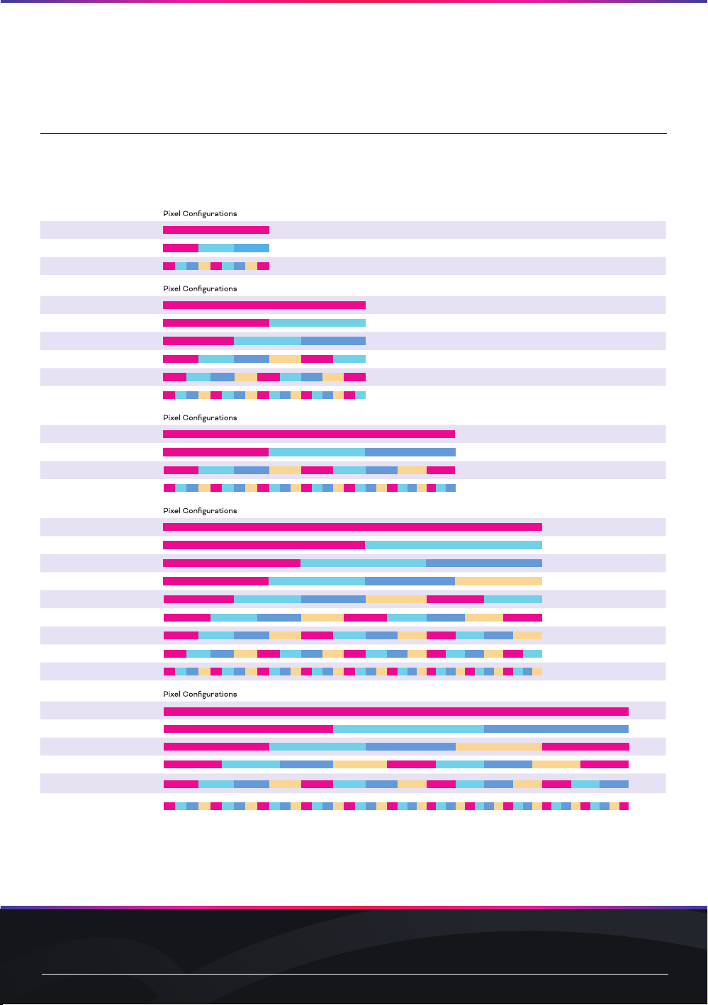
4.2 Pixel Congurations
Media Tube® Plus can be ordered in different individually controlled segments. The below list indicates
the possible configurations for each length.
Media Tube®Plus RGBW
*: Length options differ by region.
See your local Traxon representative for information.
296mm / 12”
01 Pixels
03 Pixels
*09 Pixels
596mm / 23”
01 Pixels
02 Pixels
03 Pixels
06 Pixels
09 Pixels
*18 Pixels
896mm / 35”
01 Pixels
03 Pixels
09 Pixels
*27 Pixels
1196mm / 47”
01 Pixels
02 Pixels
03 Pixels
04 Pixels
06 Pixels
09 Pixels
12 Pixels
18 Pixels
*36 Pixels
1496mm / 59”
01 Pixels
03 Pixels
05 Pixels
09 Pixels
15 Pixels
*45 Pixels
www.traxon-ecue.com ©2023 TRAXON TECHNOLOGIES. ALL RIGHTS RESERVED.
Installation Guide 02/23 V1.0 15 of 21
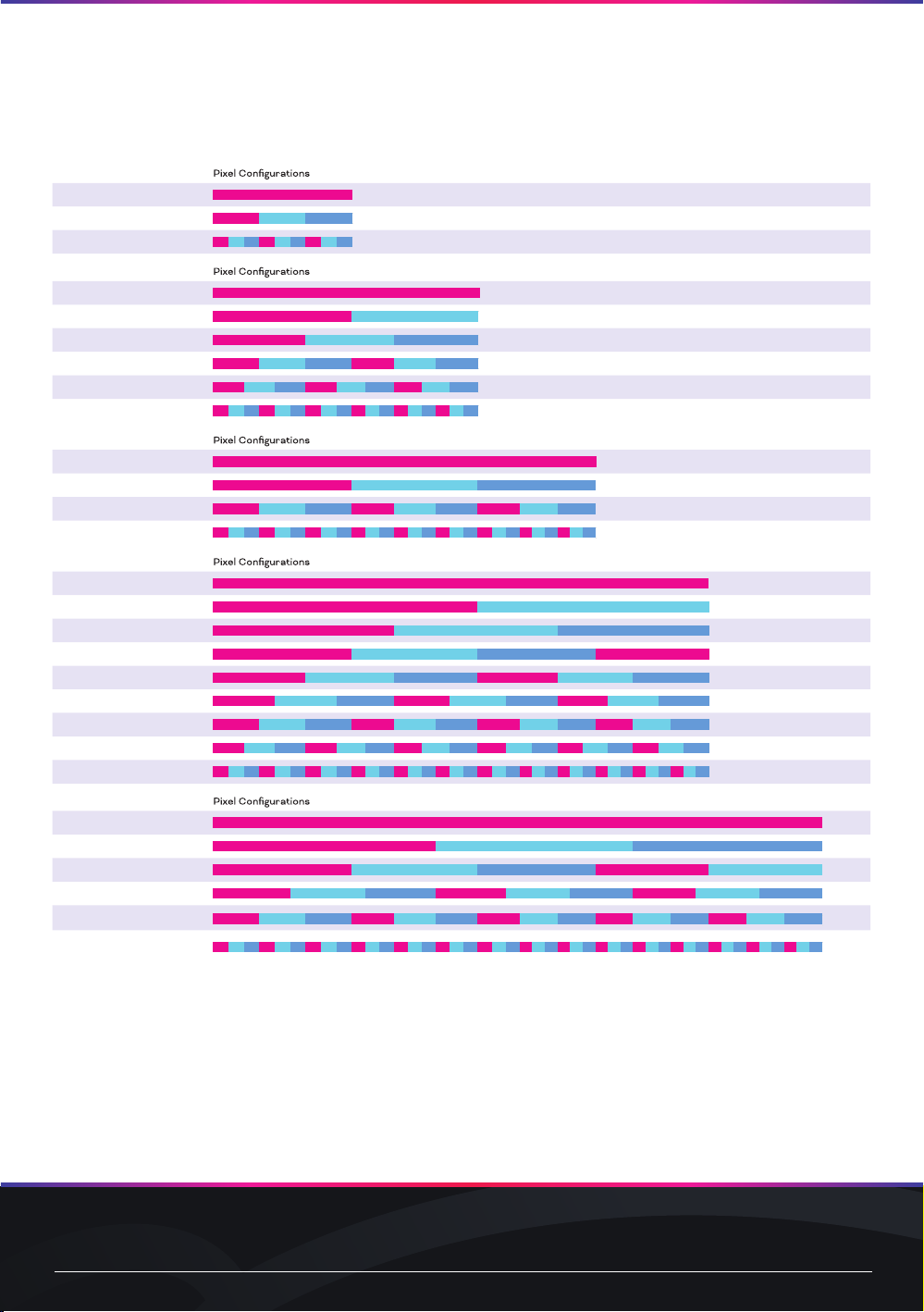
Media Tube®Plus RGB
296mm / 12”
01 Pixels
03 Pixels
*09 Pixels
596mm / 23”
01 Pixels
02 Pixels
03 Pixels
06 Pixels
09 Pixels
*18 Pixels
896mm / 35”
01 Pixels
03 Pixels
09 Pixels
*27 Pixels
1196mm / 47”
01 Pixels
02 Pixels
03 Pixels
04 Pixels
06 Pixels
09 Pixels
12 Pixels
18 Pixels
*36 Pixels
1496mm / 59”
01 Pixels
03 Pixels
05 Pixels
09 Pixels
15 Pixels
*45 Pixels
*: Length options differ by region.
See your local Traxon representative for information.
www.traxon-ecue.com ©2023 TRAXON TECHNOLOGIES. ALL RIGHTS RESERVED.
Installation Guide 02/23 V1.0 16 of 21
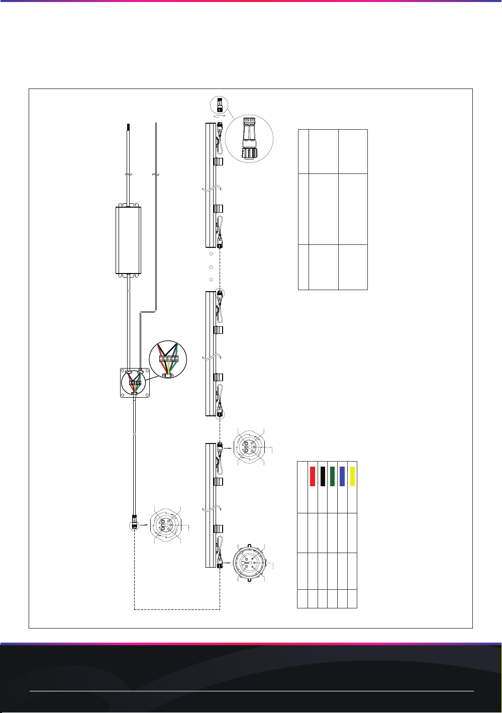
FIG.9: System Diagram– Starter Cable Installation
Signal
DC48V+
DC48V–
Data+
Data–
Address
Wire Size
17AWG
17AWG
24AWG
24AWG
24AWG
Color
Red
Black
Green
Blue
Yellow
Pin#
5
4
1
3
2
MT PLUS END CAP WITH 120Ω TERMINATOR
(AM477800055)
The Address wire is not needed between the controller and the first fixture.
This wiring diagram shows only typical connections. Actual wiring depends on Tube configuration and installation. Actual no. varies according to cable
lengths and signal source. Please consult your local Traxon office for aid.
Color Type
RGBW
Max. Daisy Chain*
12m
17m
PSU Power
240W
320W
e:pix/DMX In
300mm/12”
LED ENGINE 48V OUTDOOR 100W/240W/320W
(AM338910055/AM089330055/AM088070055)
AC 120v-277v In
MT PLUS STARTER CABLE 5-WIRE 1M/5M/30M
(AM477770055/AM477780055/AM477790055)
Installation engineer should
use appropriate hardware for
outdoor connection.
6m 100W
2
13
4
5
2
1
3
45
2
13
4
5
1. Do not connect the yellow address wire
2. Connect the black DC48V- wire to data GND
RGB 16.5m
22.5m
240W
320W
7.5m 100W
*Based on max resolution data consumption.
www.traxon-ecue.com ©2023 TRAXON TECHNOLOGIES. ALL RIGHTS RESERVED.
Installation Guide 02/23 V1.0 17 of 21
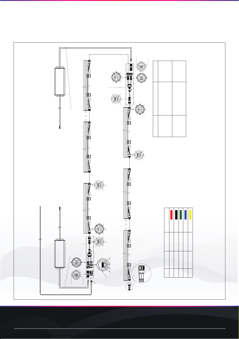
FIG.10: System Diagram – RJ45/Power Injector Kit and Power Injector Kit Installation
MT PLUS END CAP WITH 120Ω TERMINATOR
(AM477800055)
This wiring diagram shows only typical connections. Actual wiring depends on Tube configuration and installation. Actual no. varies according to cable
lengths and signal source. Please consult your local Traxon office for aid.
LED ENGINE 48V OUTDOOR 100W/240W/320W
(AM338910055/AM089330055/AM088070055)
2
1
3
45
2
13
4
5
RJ45 Female
1
DATA- 2
DATA+ 3
GND 8
2.V-
1. V+
DC48V
2. V-
1. V+
2
13
4
5
2
1
3
45
DC48V
2
1
3
45
2
13
4
5
RJ45 Male
(by others)
PSU
PSU
To secure water-proof function, DC48V in Cable diameter range must be Ø6.5mm/0.26”-8.2mm/0.32”
2
13
4
5
AC in
AC in
MT PLUS RJ45 / POWER INJECTOR
CABLE KIT (AM477840055)
MT PLUS POWER INJECTOR
CABLE KIT (AM477850055)
LED ENGINE 48V OUTDOOR 100W/240W/320W
(AM338910055/AM089330055/AM088070055)
Installation engineer should
use appropriate hardware for
outdoor connection.
Color Type
RGBW
Max. Daisy Chain*
12m
17m
PSU Power
240W
320W
6m 100W
RGB 16.5m
22.5m
240W
320W
7.5m 100W
e:pix/DMX In
Signal
DC48V+
DC48V–
Data+
Data–
Address
Wire Size
17AWG
17AWG
24AWG
24AWG
24AWG
Color
Red
Black
Green
Blue
Yellow
Pin#
5
4
1
3
2
*Based on max resolution data consumption.

www.traxon-ecue.com ©2023 TRAXON TECHNOLOGIES. ALL RIGHTS RESERVED.
Installation Guide 02/23 V1.0 18 of 21
5. Care and Maintenance
Traxon products are of superior design and quality and should be treated with care. The
recommendations below will help fulll any warranty obligations and gain good use and longevity from
the products.
—Do not attempt or use the product(s) until you read and understand the installation instructions.
Failure to adhere to these instructions could result in serious injury or property damage.
—Do not use product(s) if cables are damaged.
—Do not connect cables and connectors when wet or in wet area. Moisture on bare connectors can
cause electric shock and damage to product(s).
—Do not use product(s) in extreme heat environment. Ensure there is sucient airow and use cool
air circulation if required.
—Do not drop, knock, or shake product(s). Rough handling can damage the electronics and void the
warranty.
—Do not use harsh chemicals, cleaning solvents, or strong detergents to clean products. Wipe with a
damp cloth on housings and a dry cloth on electronics to remove dirt or dust.
—Do not attempt to service or repair the product(s) unless done by an authorized service personnel.
Contact your local Traxon oce or distributor for details.
—If the product is not working as specied, please contact your nearest authorized service center
or Traxon Technologies oce for assistance.
—The light source of this luminaire is not replaceable; when the light source reaches its end of life the
whole luminaire shall be replaced.

www.traxon-ecue.com ©2023 TRAXON TECHNOLOGIES. ALL RIGHTS RESERVED.
Installation Guide 02/23 V1.0 19 of 21
6. Technical Specication
Media Tube®Plus RGBW
Length Option* Direct View Diused View
296mm /
12”
596mm /
23”
896mm /
35”
1196mm /
47”
1496mm /
59”
296mm /
12”
596mm /
23”
896mm /
35”
1196mm /
47”
1496mm /
59”
Color Range: 16.7 Million additive RGB colors; White 6500K
Light Source: 18 RGB +
9 White
36 RGB +
18 White
54 RGB +
27 White
72 RGB +
36 White
90 RGB +
45 White
18 RGB +
18 White
36 RGB +
36 White
54 RGB +
54 White
72 RGB +
72 White
90 RGB +
90 White
Beam Angle: 110° 120° x 180°
Power Input*: 48V DC
Power Consumption (typ).: 4.5W 8.4W 12.6W 16.8W 21W 4.5W 8.4W 12.6W 16.8W 21W
Weight: 0.37kg /
0.82lb
0.66kg /
1.46lb
0.95kg /
2.09lb
1.15kg /
2.54lb
1.53kg /
3.37lb
0.35kg /
0.77lb
0.62kg /
1.37lb
0.9kg /
1.98lb
1.08kg /
2.38lb
1.45kg /
3.2lb
Operating Temperature: –40°C to +60°C / –40°F to +140°F
Storage Temperature: –40°C to +80°C / –40°F to +176°F
Media Tube®Plus RGB
Length Option* Direct View Diused View
296mm /
12”
596mm /
23”
896mm /
35”
1196mm /
47”
1496mm /
59”
296mm /
12”
596mm /
23”
896mm /
35”
1196mm /
47”
1496mm /
59”
Color Range: 16.7 Million additive RGB colors
Light Source: 18 RGB 36 RGB 54 RGB 72 RGB 90 RGB 18 RGB 36 RGB 54 RGB 72 RGB 90 RGB
Beam Angle: 110° 120° x 180°
Power Input*: 48V DC
Power Consumption (typ).: 3.5W 6.6W 9.9W 13.2W 16.5W 3.5W 6.6W 9.9W 13.2W 16.5W
Weight: 0.37kg /
0.82lb
0.66kg /
1.46lb
0.95kg /
2.09lb
1.15kg /
2.54lb
1.53kg /
3.37lb
0.35kg /
0.77lb
0.62kg /
1.37lb
0.9kg /
1.98lb
1.08kg /
2.38lb
1.45kg /
3.2lb
Operating Temperature: –40°C to +60°C / –40°F to +140°F
Storage Temperature: –40°C to +80°C / –40°F to +176°F
As with all electronic devices, LED output degrades over time - a term called lumen depreciation. This
also explains why it is nearly impossible to expect photometric performances of two LED products
with dierent service life spans to be the same. The rate of LED degradation is a complex function of
many factors such as operating eciency, duration of continuous operation, and operating conditions
(e.g. ambient temperature).
Because LEDs are semiconductor devices, their performances are subject to inherent variability
commonly found in semiconductor industry. To improve consistency in performance across the
same product, LED manufacturers “sort” LEDs into bins according to dierent preset parameters,
such as forward driving voltage, illumination, etc. Whereas binning is a sorting function, it is not a
correction process. Inherent variability in the manufacturing process always results in dierent
binning distributions according to dierent production lots. Traxon uses automatically binned LEDs on
its products, thereby minimizing output variations within the model range.
*: Length options dier by region. See your local Traxon representative for information.

www.traxon-ecue.com ©2023 TRAXON TECHNOLOGIES. ALL RIGHTS RESERVED.
Installation Guide 02/23 V1.0 20 of 21
7. Troubleshooting
CAUTION: Ensure power supply is OFF when disconnecting / connecting cables.
Problem Cause Possible Solutions
Product does
NOT light up after
installation
Incorrect power connection —Check Mains Power
—Check power supply leads and wire
connections
—Ensure output wires are connected with
proper polarity
—Check if LED Engine’s secondary output is
working as specied.
Shadowing Light source covered —Check for cables, wires or unwanted debris
covering LED light source
Modules are dim Excess products connected —Ensure the power supplies are not
overloaded due to an excess of products
connected
Flickering Incorrect power input/Excess
products connected
—Ensure the input voltage is correct
—Ensure the power supplies are not
overloaded due to an excess of products
connected
If problems persist or the product is not working as specied, please contact your Traxon
Technologies oce for assistance.
8. Warranty Statement
Traxon Technologies warrants its Products against material or workmanship defects for a period of
ve (5) years from date of invoicing, provided that the purchased items are used under the conditions
stated in this user manual.
Please refer www.traxon-ecue.com for all warranty terms and conditions.
This manual suits for next models
2
Table of contents
Other Traxon Dj Equipment manuals


