Traxon ecue Vista Plus 1x200W RGBW User manual
Vista Plus
INSTALLATION GUIDE
V1.1
Cover:
Vista Plus 1x200W RGBW
Vista Plus 1x200W White
Vista Plus 2x200W RGBW
Vista Plus 2x200W White

www.traxon-ecue.com ©2023 TRAXON TECHNOLOGIES. ALL RIGHTS RESERVED.
Installation Guide 08/23 V1.1 2 of 29
www.traxon-ecue.com ©2023 TRAXON TECHNOLOGIES. ALL RIGHTS RESERVED.
Installation Guide 08/23 V1.1 3 of 29
CONTENT
1. INTRODUCTION 4
2. INSTALLATION 12
3. POWER AND DATA WIRING 21
4. CONFIGURATION 25
5. TROUBLESHOOTING 27
6. WARRANTY INFORMATION 27
7. APPENDIX 28

www.traxon-ecue.com ©2023 TRAXON TECHNOLOGIES. ALL RIGHTS RESERVED.
Installation Guide 08/23 V1.1 2 of 29
www.traxon-ecue.com ©2023 TRAXON TECHNOLOGIES. ALL RIGHTS RESERVED.
Installation Guide 08/23 V1.1 3 of 29
SAFETY AND OPERATION
This installation guide uses the following special statement categories to alert you to key items:
1. WARNING - Indicates a hazardous situation that, if not avoided, could result in death or serious injury.
2. CAUTION - Indicates a hazardous situation that, if not avoided, could result in minor or moderate injury.
3. NOTICE - Indicates information considered important for the proper operation of the product but not hazard
related.
4. Please review this manual completely prior to beginning the installation process and take note of the
following:
• The Traxon luminaire and associated accessories must be installed by a qualified person in conjunction
with all applicable electrical codes and standards.
• The Traxon luminaire does not contain any user-serviceable parts. Opening of the luminaire will void the
warranty.
• Do not use the product if the cables are damaged.
• Handle the luminaire carefully to prevent damage during installation. Rough handling may damage the
internal electronics and void the warranty.
• Do not attempt installation in wet or severe weather conditions.
• Do not stare directly into the light beam while the unit is illuminated.
• IP66 rated. The Traxon luminaire is not suitable for direct immersion in water.
• Do not operate the Traxon luminaire without a connection to earth surface.
• The Traxon luminaire is designed for operation at 120-277VAC. Voltages outside of this range may damage
the fixture and will void the warranty.
• The Traxon luminaire housing may become hot during normal operation and present a risk of burn
injury and fire hazard. Exercise caution when working in proximity to the luminaire and make sure that
combustible material does not contact the housing or lens.
• Failure to keep the luminaire within the operating temperature range (-30°C to +55°C/-22°F to +131°F) will
result in improper operation and will void the product warranty.
• Do not use harsh chemicals, cleaning solvents or strong detergents when cleaning the luminaire.
• Persons installing this product should make sure:
i. The installation complies with all applicable codes, state and local laws, ordinances, standards and
safety regulations.
ii. The installation environment is carefully studied and suitable surge protection measure(s) is taken.
Suggested surge protection measures for outdoor application should reach “Live to Neutral” 5kV,
“Live/Neutral to Earth” 10kV.
iii. All luminaires can pass over-voltage test up to “Live to Neutral” 1kV, “Live/Neutral to Earth” 2kV
according to EN61547 standard.
iv. He or she is qualified for the handling of electrical equipment.

www.traxon-ecue.com ©2023 TRAXON TECHNOLOGIES. ALL RIGHTS RESERVED.
Installation Guide 08/23 V1.1 4 of 29
www.traxon-ecue.com ©2023 TRAXON TECHNOLOGIES. ALL RIGHTS RESERVED.
Installation Guide 08/23 V1.1 5 of 29
1. INTRODUCTION
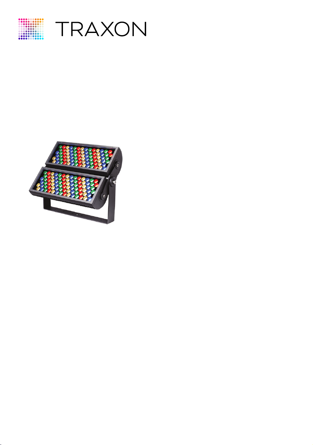
1.1 Product Overview
The Vista Plus is an AC line powered, high brightness luminaire. Controllable with DMX512, the Vista Plus is
available in 200W and 400W outputs, 12 beam angle options, standard & custom finishes which can meet the
needs for most projects. The daisy chain topology, and direct-wire nature of the fixture via the two integral cable
whips allow for simple installation into existing installations and new structures, and is ideal for high-rise and tower
illumination.
This manual is intended for use with DMX/RDM versions of the Vista Plus.
1.2 Getting Assistance
Additional product information is available on the Traxon web site:
• www.traxon-ecue.com
For additional support, please contact Traxon Technical Support:
• TRXT[email protected]
For Americas Regional Support:
• (978) 570-3189 – Business Hours Technical Support
• +1 (978) 267-5346 – After Hours Technical Support
For Asia Pacific Regional Support
For Europe, Middle East and Africa Regional Support
www.traxon-ecue.com ©2023 TRAXON TECHNOLOGIES. ALL RIGHTS RESERVED.
Installation Guide 08/23 V1.1 4 of 29
www.traxon-ecue.com ©2023 TRAXON TECHNOLOGIES. ALL RIGHTS RESERVED.
Installation Guide 08/23 V1.1 5 of 29
1.3 Dimensions
FIG.1: Vista Plus 1x200W
357.2mm
(14.1")
271.5mm
(10.7")
Data Cable, diameter:
Ø 8.1mm (Ø 0.3")
Power Cable, diameter:
Ø 7.8mm (Ø 0.3")
176.2mm
(6.9")
14mm Hex Key required to adjust
Fixture angle (Available from Traxon)
221mm
(8.7")
101.6mm (4")
81mm (3.2")
689mm
(27.1")
674.7mm
(26.6")
689mm
(27.1")
357.2mm
(14.1")
271.5mm
(10.7")
674.7mm
(26.6")
674.7mm
(26.6")

www.traxon-ecue.com ©2023 TRAXON TECHNOLOGIES. ALL RIGHTS RESERVED.
Installation Guide 08/23 V1.1 6 of 29
www.traxon-ecue.com ©2023 TRAXON TECHNOLOGIES. ALL RIGHTS RESERVED.
Installation Guide 08/23 V1.1 7 of 29
FIG.2: Vista Plus 2x200W
14mm Hex Key
required to adjust
Fixture angle
(Available from
Traxon)
17mm Hex Key
required to adjust
Fixture angle
(Available from
Traxon)
Data Input/OutputCable
diameter:ø8.1mm
Power Cable
diameter:ø7.8mm
738mm
(29.1")
657.2mm
(25.9")
455.6mm
(17.9")
176.2mm
(6.9")
576.3mm
(22.7")
267.5mm
(10.5")
643mm
(25.3")
2'-1 7/8"
2'-4"
101.6mm (4")
304.8mm (12")
763.6mm (30.1")
506.4mm (19.9")
4"
4"
1'
2'-6 1/16"
1'-7 15/16"
576.3mm (22.7")
Data Input/OutputCable
diameter: ø8.1mm(Ø 0.3")
Power Cable
diameter:ø7.8mm(Ø 0.3")
2'-4"
2'-4"
2'-1 7/8"
1'-5 15/16"
6 15/16"
1'-10 11/16"
10 11/16"
2'-1 5/16"
576.3mm
(22.7")
657.2mm
(25.9")
101.6mm (4")
738mm
(29.1")
738mm
(29.1")
Additional Accessories (Optional accessory for 1x200W and 2x200W units)
A additional accessories kit may be ordered for the 1x200W and 2x200W luminaire models. This kit allows for mounting
directly into a suitable angle. The kit can be installed onto the luminaires directly. Additional accessories include a Rock
Guard to protect the lens, and an Angled Glare shield and Open Glare shield to help hide the light source.
www.traxon-ecue.com ©2023 TRAXON TECHNOLOGIES. ALL RIGHTS RESERVED.
Installation Guide 08/23 V1.1 6 of 29
www.traxon-ecue.com ©2023 TRAXON TECHNOLOGIES. ALL RIGHTS RESERVED.
Installation Guide 08/23 V1.1 7 of 29
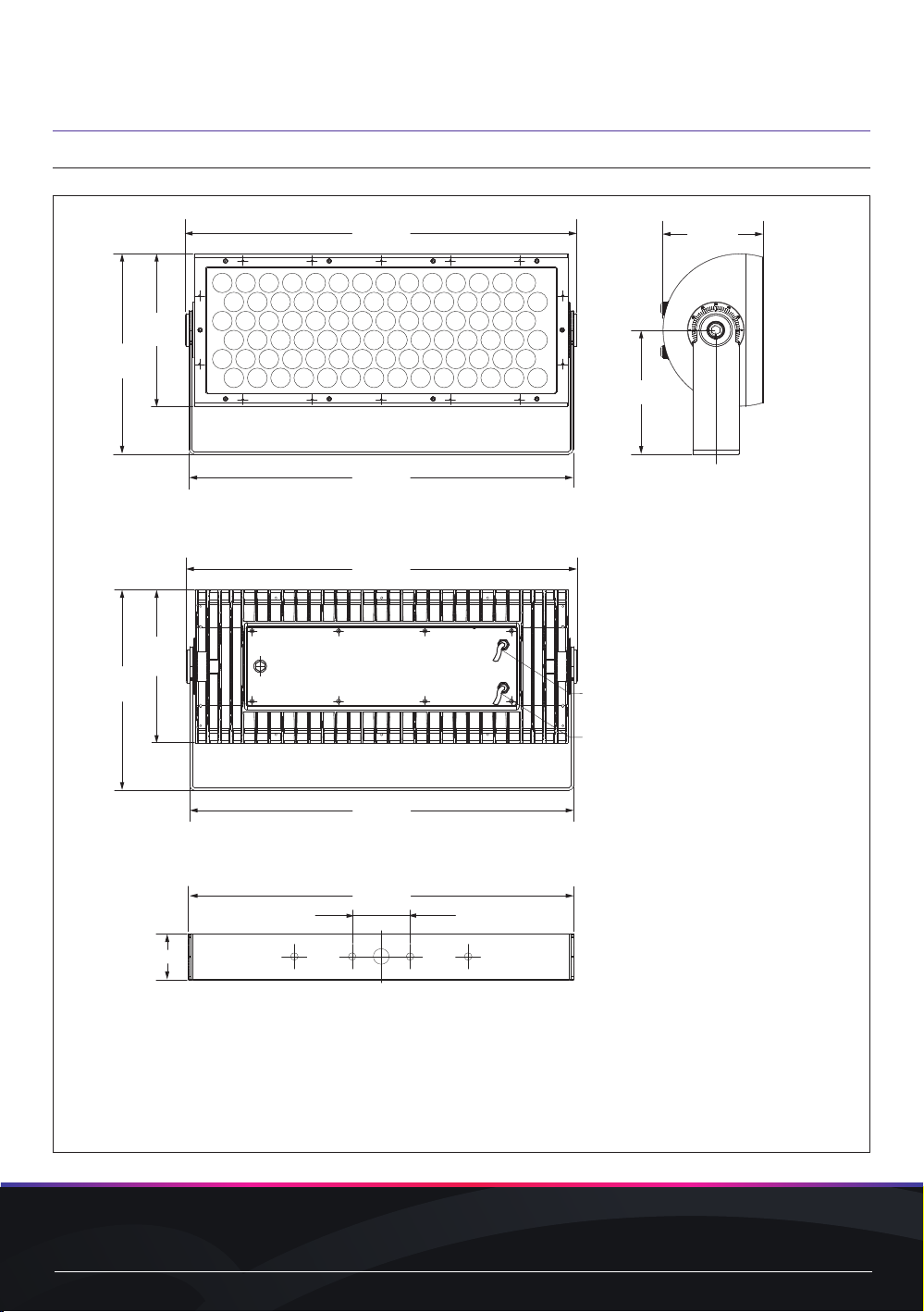
FIG.3: Vista Plus Accessories-Full/Half Glare Shield
Full Glare Shield
Half Glare Shield

www.traxon-ecue.com ©2023 TRAXON TECHNOLOGIES. ALL RIGHTS RESERVED.
Installation Guide 08/23 V1.1 8 of 29
www.traxon-ecue.com ©2023 TRAXON TECHNOLOGIES. ALL RIGHTS RESERVED.
Installation Guide 08/23 V1.1 9 of 29
FIG.4: Vista Plus Accessories-Pole Mounting Supporter/Rock Guard
Pole-Mounting Supporter
Rock Guard
www.traxon-ecue.com ©2023 TRAXON TECHNOLOGIES. ALL RIGHTS RESERVED.
Installation Guide 08/23 V1.1 8 of 29
www.traxon-ecue.com ©2023 TRAXON TECHNOLOGIES. ALL RIGHTS RESERVED.
Installation Guide 08/23 V1.1 9 of 29
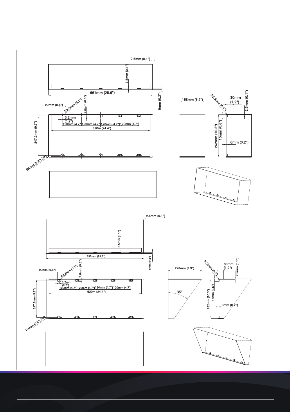
FIG.5: Vista Plus Accessories-Additional Frame
Spread Lens Frame

www.traxon-ecue.com ©2023 TRAXON TECHNOLOGIES. ALL RIGHTS RESERVED.
Installation Guide 08/23 V1.1 10 of 29
www.traxon-ecue.com ©2023 TRAXON TECHNOLOGIES. ALL RIGHTS RESERVED.
Installation Guide 08/23 V1.1 11 of 29
1.4 Packing Contents
FIG.6: Packing Contents
1 x Vista Plus (size/model based on order)
1.5 Component Overview
Luminaire Options
The Vista Plus luminaire is available in the following sizes:
Model Weight Power Consumption
(Nominal)
Power
Factor
Input Voltage
Range
Operating
Temperature
Minimum Starting
Temperature
1x200W 22.3kg
(49.2 lbs.)
200W
≥0.9 120-277VAC
50/60 Hz
-30°C to +55°C
(-22°F to +131°F) -20°C (-4°F)
2x200W 45.5kg
(100.3 lbs.)
400W
The Vista Plus luminaire is available with the following optical engines:
Model Optical Engine Lens Options DMX Control
Channels
Color Temperature
1x200W Color Changing
(RGBW)
3° native; 5°, 8°, 10°,
15°, 20°, 30°, 40°, 55°,
80°, 50°x10°, 50°x5° via
accessory Internal Louver
(Standard)
4 RGBW (White CCT: 4000K standard)
Other White CCT and RGBA available
White + Color 13000K / 4000K
2700K, 3500K, 5000K, 6500K, Red,
Green, Blue, Amber available
2x200W Color Changing
(RGBW)
4 RGBW (White CCT: 4000K standard)
Other White CCT and RGBA available
White + Color 13000K / 4000K
2700K, 3500K, 5000K, 6500K, Red,
Green, Blue, Amber available
www.traxon-ecue.com ©2023 TRAXON TECHNOLOGIES. ALL RIGHTS RESERVED.
Installation Guide 08/23 V1.1 10 of 29
www.traxon-ecue.com ©2023 TRAXON TECHNOLOGIES. ALL RIGHTS RESERVED.
Installation Guide 08/23 V1.1 11 of 29
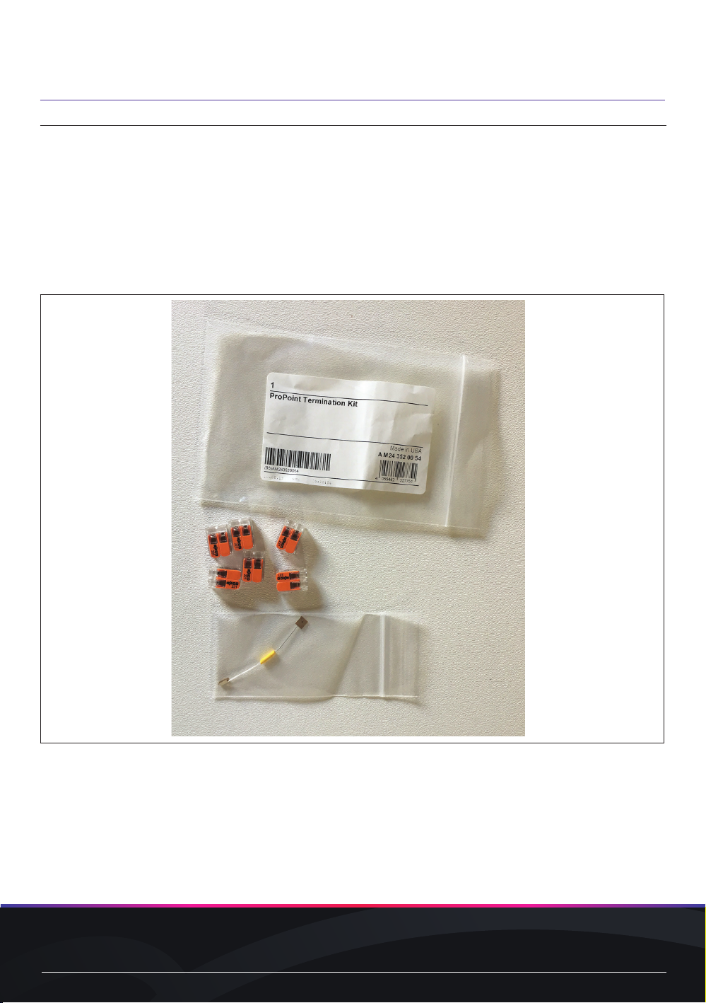
1.6 Additional Accessories
Termination Kit
A ProPoint termination kit (part number AM243520054) may be purchased separately. This kit contains the
following components:
- (6) Splicing wire connectors: For use in connecting data cable conductors.
NOTE Wire nuts are not permissible for use with data connections and will void warranty.
- 120 Ohm resistor for use in terminating the DMX512 data line at the last luminaire.
FIG.7: ProPoint Termination Kit
www.traxon-ecue.com ©2023 TRAXON TECHNOLOGIES. ALL RIGHTS RESERVED.
Installation Guide 08/23 V1.1 12 of 29
www.traxon-ecue.com ©2023 TRAXON TECHNOLOGIES. ALL RIGHTS RESERVED.
Installation Guide 08/23 V1.1 13 of 29
2. INSTALLATION
Each Vista Plus luminaire is shipped with a mounting bracket suitable for Surface/Pole mount
applications. This mounting plate is pre-installed at the mounting interface of the luminaire.
2.1 Surface Mount Installation
Required Tools
1x200W Model 14mm and 17mm Hex Key
2x200W Model 14mm and 17mm Hex Key
Surface Mount Installation
FIG.8: Vista Plus Surface Mount Installation
Preparation
• Remove the Vista Plus luminaire from the packaging and place the unit on a level surface.
Bracket Preparation and Mounting
CAUTION It is the installer’s responsibility to ensure that the mounting surface can handle the
static weight of the fixture as well as dynamic loading from environmental factors
such as wind and snow/ice buildup. The use of Grade 5 or higher hardware is
recommended.
• Make sure that the bolts on the mounting surface align with the holes on the surface mount bracket
• Install the luminaire to the mounting surface and secure using appropriate hardware (by others).
NOTICE The Traxon Luminaire should be installed with the power and data cables exiting
the housing directly down when the luminaire is mounted on a vertical surface. For
applications that require horizontal orientation of the power and data cables, the
installer shall apply RTV silicone to the cable gland entry points. The luminaire shall
not be installed with the power and data cabling oriented up.

www.traxon-ecue.com ©2023 TRAXON TECHNOLOGIES. ALL RIGHTS RESERVED.
Installation Guide 08/23 V1.1 12 of 29
www.traxon-ecue.com ©2023 TRAXON TECHNOLOGIES. ALL RIGHTS RESERVED.
Installation Guide 08/23 V1.1 13 of 29
Surface Mount Installation Steps
• After placing the stainless steel mounting bracket on the mounting surface, mark the positions of 4 mounting
holes and drill 4 x M12 expanding anchors into the holes with the electric drill.
FIG.9: Surface Mounting Step 1
101.6mm (4")
304.8mm (12")
763.6mm (30.1")
506.4mm (19.9")
101.6mm (4")
100.8mm (4")
(Screws are not included)
Bracket Installation
• Mark the positions of mounting holes and drill M12 expanding anchors into the holes with the electric drill. Fix
the M12*50 Outer hexagon bolt/φ12 flat washer/φ12 Spring washer as the following picture shows to install the
bracket.
NOTICE It is the responsibility of the installer to ensure that the mechanical fixings are
appropriate for the task and if necessary, approved by a structural engineer as the
installation scenario is unique for each luminaire
FIG.10: Bracket Mounting

www.traxon-ecue.com ©2023 TRAXON TECHNOLOGIES. ALL RIGHTS RESERVED.
Installation Guide 08/23 V1.1 14 of 29
www.traxon-ecue.com ©2023 TRAXON TECHNOLOGIES. ALL RIGHTS RESERVED.
Installation Guide 08/23 V1.1 15 of 29
• After aligning 4φ13mm holes and expansion screws on the floor of the stainless steel mounting bracket, lock
the mounting bracket.
FIG.11: Surface Mounting Step 2
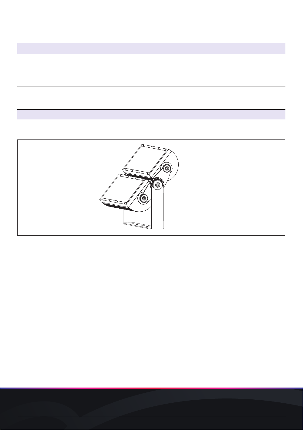
• Loosen the adjusting bolts with 17mm Hex Key, adjust the overall angle of the luminaire and tighten
the adjusting bolts.
• Loosen the adjusting bolts with 14mm Hex Key, adjust the single-head exposure angle and tighten
the adjusting bolts.
CAUTION Do not rotate the luminaire more than 180 degrees. Rotating more than 180 degrees
may cause the power and/or data cables to bind inside the unit resulting in damage.
FIG.12: Surface Mounting Step 3
A 17mm hex key can be used on the center adjustment bolt to
enable you to change the angle of the fixture.
A 14mm hex key can be used on the outer
adjustment bolts to enable you to change the
angle of the individual heads.

www.traxon-ecue.com ©2023 TRAXON TECHNOLOGIES. ALL RIGHTS RESERVED.
Installation Guide 08/23 V1.1 14 of 29
www.traxon-ecue.com ©2023 TRAXON TECHNOLOGIES. ALL RIGHTS RESERVED.
Installation Guide 08/23 V1.1 15 of 29
2.2 Pole Mount Installation (Vertical Mounting only)
Required Tools
1x200W Model 14mm and 17mm Hex Key
2x200W Model 14mm and 17mm Hex Key
Pole Mount Installation
FIG.13: Vista Plus pole Mount Installation
Preparation
• Remove the Traxon luminaire from the packaging and place the unit on a level surface.
Pole Mounting Steps
• Mark the positions of the 4 mounting holes and then drill 4 x M12 holes with an electric drill. Mount the luminaire
bracket to the post mount plate using suitable M12 fixings (e.g. M12 bolt, spring washer and locking M12 nut).
www.traxon-ecue.com ©2023 TRAXON TECHNOLOGIES. ALL RIGHTS RESERVED.
Installation Guide 08/23 V1.1 16 of 29
www.traxon-ecue.com ©2023 TRAXON TECHNOLOGIES. ALL RIGHTS RESERVED.
Installation Guide 08/23 V1.1 17 of 29
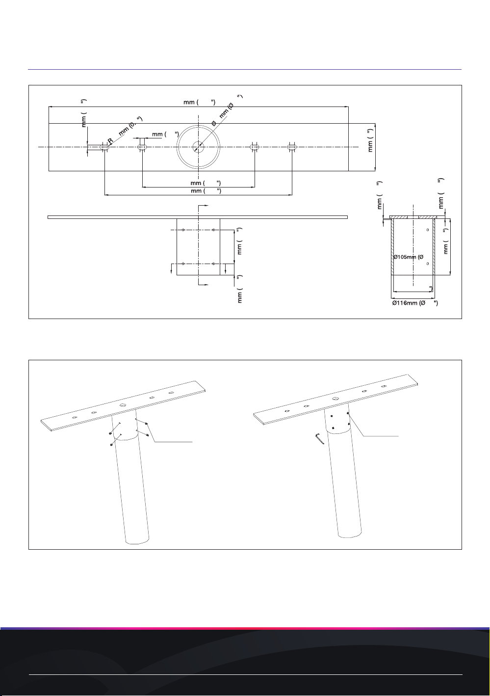
FIG.14: Pole Mounting Step 1
90 3.5
30 1.2
3 0.1
8 0.3
150 5.9
4.1)
4.6
30 1.2
800 31.5
500 19.7
300 11.8
12 0.5
6.5 3
126 5
13.3 0.5
• Fix the inner hexagon screw to fasten the pole mounting supporter onto the pole.
FIG.15: Pole Mounting Step 2
4 mm hex
wrench to fasten
screws
4-M8*10
hex socket screw
(Screws and pole are not included)
www.traxon-ecue.com ©2023 TRAXON TECHNOLOGIES. ALL RIGHTS RESERVED.
Installation Guide 08/23 V1.1 16 of 29
www.traxon-ecue.com ©2023 TRAXON TECHNOLOGIES. ALL RIGHTS RESERVED.
Installation Guide 08/23 V1.1 17 of 29
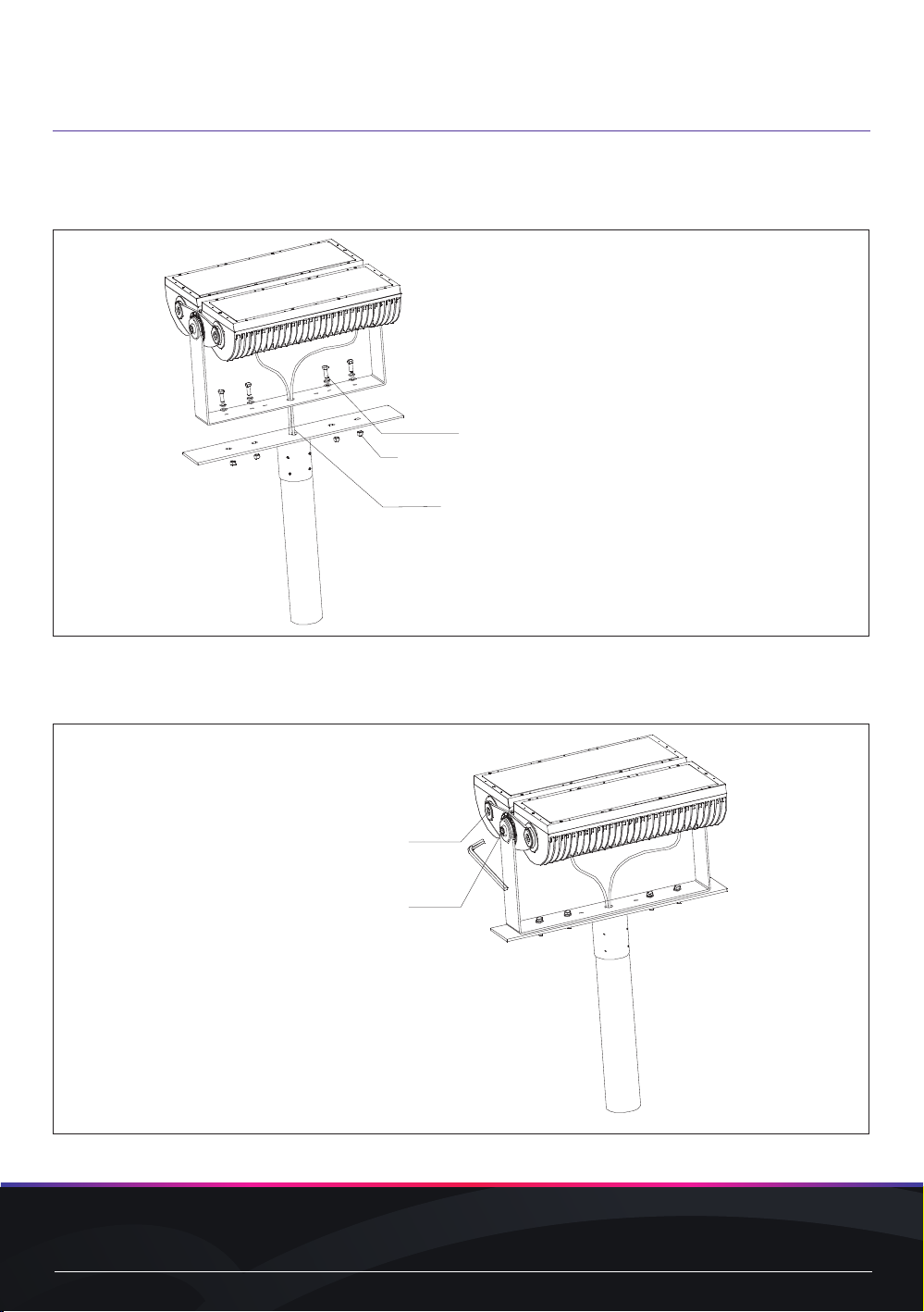
• Pull the power and data cabling through the pole fitting (by others). Install the luminaire onto the
pole fitting and secure mounting screws and lock nuts.
FIG.16: Pole Mounting Step 3
M12*50 hex bolt/
φ12 flat washer/φ12 Spring washer
M12 Nut
Put the connected signal cable/power
cable into the pole
(Screws and pole are not included)
• Fix the luminaire and use a suitable inner Hex Key to adjust the luminaire to a target angle.
FIG.17: Pole Mounting Step 4
14 mm hex key
to adjust the angle of single module
17 mm hex key
to adjust the angle of whole luminaire
www.traxon-ecue.com ©2023 TRAXON TECHNOLOGIES. ALL RIGHTS RESERVED.
Installation Guide 08/23 V1.1 18 of 29
www.traxon-ecue.com ©2023 TRAXON TECHNOLOGIES. ALL RIGHTS RESERVED.
Installation Guide 08/23 V1.1 19 of 29
Recording the UID (DMX/RDM Model Only)
Each Vista Plus luminaire is marked with a Unique Identifier (UID) on the product label. This UID is
used to address the luminaire for correct operation.
Example: 16DC:0834AA0B
AA0B represents the designation shown on the label.
Before completing installation, record each luminaire’s UID in a manner similar to the table included at
the end of this manual.
FIG.18: UID Location
Record the UID code
and physical location
from the label located
on the side of each
luminaire.
UID: *0834
2.3 Power Wiring
The Vista Plus luminaire is supplied with a 1.8 meter (6 foot) long power feed cable. This cable may be
field-cut to the required length by the installer.
WARNING Risk of electrical shock. Make sure that the branch circuit is disconnected prior to
installation or inspection..
CAUTION Make sure that the cable is protected from cuts and abrasions that may result in
damage to the outer jacket.
CAUTION IP failure induced by stressed/damaged cable entry points during or after installation
will void the product warranty.
NOTICE A voltage divider is recommended (and may be required by local electrical code)
when a single junction box is utilized for termination of the power supply and data
cables.
NOTICE Cable bend radius must NOT be less than the Minimum Bending Radius (4 X Cable
Diameter) as specified by cable manufacturer and the Non-Bendable Length of 5cm
(2in) near the cable gland MUST be adhered to. In addition to the Minimum Bending
Radius, ensure that 5cm (2in) of cable at the connector junction is kept straight.

www.traxon-ecue.com ©2023 TRAXON TECHNOLOGIES. ALL RIGHTS RESERVED.
Installation Guide 08/23 V1.1 18 of 29
www.traxon-ecue.com ©2023 TRAXON TECHNOLOGIES. ALL RIGHTS RESERVED.
Installation Guide 08/23 V1.1 19 of 29
2.4 Glare Shield Installation (Optional Accessory)
Required Tools
1x200W Model 5mm and 3mm Hex Keys
2x200W Model 6mm and 4mm Hex Keys
Preparation
• Remove the Traxon luminaire from the packaging and place the unit on a level surface.
FIG.19: Accessories Structure
Accessories Installation
• Fix the screws as the following picture shows to install the additional accessories as your requirements.
FIG.20: Accessories Mounting
Angled Glare Shield Mounting
Open Glare Shield Mounting
Spread Lens Frame Mounting
Rock Guard Mounting

www.traxon-ecue.com ©2023 TRAXON TECHNOLOGIES. ALL RIGHTS RESERVED.
Installation Guide 08/23 V1.1 20 of 29
www.traxon-ecue.com ©2023 TRAXON TECHNOLOGIES. ALL RIGHTS RESERVED.
Installation Guide 08/23 V1.1 21 of 29
CAUTION Ensure that the mounting surface and hardware are suitable for the luminaire weight.
Final Installation
NOTE For ease of installation and Safety, the following step may require 2 people to
perform. This is largely dependent on the location/orientation of the junction
box and the size of the fixture being mounted. All installers should refer to their
occupational safety and best practice guidelines when performing these tasks.
• Install the luminaire onto the mounting bracket and secure the set screws and lock nuts.
CAUTION Ensure that the power and data cabling is routed so that the luminaire mounting
interface does not crush the power and/or data cable jacketing.
• Tighten both set screws so that each screw engages securely in the surface mount bracket groove.
CAUTION Both set screws must engage within the groove. Failure of the set screws to engage
the groove could result in the luminaire separating from the surface mount bracket.
• Tighten both lock nuts over the set screws. Grasp the luminaire body and rotate it back and forth on
the mounting bracket to ensure that the fixture is securely fastened.
CAUTION Do not rotate the luminaire more than 180 degrees. Rotating more than 180 degrees
may cause the power and/or data cables to bind inside the unit resulting in damage.
This manual suits for next models
3
Table of contents
Other Traxon Dj Equipment manuals


