Treaton MPR6-03 User manual

Patient Monitor
MPR6-03
User Manual
RM 501.01.000-01-01 UM
Version 7, 05/2020

2

3
CONTENT
1. DEVICE DESCRIPTION.......................................................................................................................................6
1.1. INTRODUCTION ...................................................................................................................................................6
1.1.1. Intended Use...............................................................................................................................................6
1.1.2. Basics of Operation and Construction........................................................................................................7
1.1.3. General.......................................................................................................................................................9
1.1.4. Revision History........................................................................................................................................10
1.1.5. Symbols and Marks...................................................................................................................................11
1.1.6. General Specifications..............................................................................................................................14
1.2. GETTING STARTED......................................................................................................................................22
1.2.1. Appearance and Controls.........................................................................................................................22
1.2.2. Operating Conditions ...............................................................................................................................25
1.2.3. Safety Instructions ....................................................................................................................................26
1.2.4. Preparing to Turn on the Device ..............................................................................................................28
1.2.5. Disinfection...............................................................................................................................................29
1.3. DEVICE CONTROL........................................................................................................................................30
1.3.1. Display (Screen Configuration)................................................................................................................30
1.3.2. Touch Panel..............................................................................................................................................31
1.3.3. Control Buttons.........................................................................................................................................31
1.3.4. Manipulator (encoder)..............................................................................................................................31
1.3.5. Configuring of Curves on the Screen........................................................................................................32
1.3.6. Setting of Date and Time ..........................................................................................................................33
1.3.7. Setting of Sound Alarm Volume................................................................................................................34
1.3.8. Setting of General Parameters, Modes of Gas Analysis and Displaying of HR/ PR and RR....................35
1.3.9. Setting of Profile.......................................................................................................................................37
1.3.10. Setting of Digital Parameters and Alarm Thresholds.............................................................................40
1.3.11. Setting of ECG-channel Parameters.......................................................................................................43
1.3.12. Setting of Respiratory Parameters Module.............................................................................................45
1.3.13. Settings of Pulse Oxymetry Module........................................................................................................46
1.3.14. Settings of NIBP Module.........................................................................................................................47
1.3.15. Settings of the Thermometry Module ......................................................................................................48
1.3.16. Settings of the Capnometry Module........................................................................................................49
1.3.17. Settings of Multigas Module ...................................................................................................................50
1.3.18. Settings of the IBP Module .....................................................................................................................51
1.3.19. System Reset............................................................................................................................................52
1.4. ALARMS.........................................................................................................................................................53
1.4.1. Alarm System............................................................................................................................................53
1.4.2. Alarm Messages........................................................................................................................................54
1.4.3. Silencing the Audible Alarm .....................................................................................................................55
1.4.4. Alarms of the Pulse Oximetry Module......................................................................................................56
1.4.5. Alarms of the ECG and Respiratory Parameters Modules.......................................................................58
1.4.6. Alarms of NIBP Module............................................................................................................................59
1.4.7. Alarms of the Thermometry Module .........................................................................................................61
1.4.8. Alarms of the Capnometry Module...........................................................................................................62
1.4.9. Alarms of the Multigas Module.................................................................................................................64
1.4.10. Alarms of the IBP Module ......................................................................................................................66
1.4.11. General Technical Alarms......................................................................................................................66
2. MEASUREMENT OF PARAMETERS..............................................................................................................67
2.1. MONITORING OF ARTERIAL OXYGEN SATURATION (SPO2)...............................................................67
2.1.1. Application of Finger SpO2Sensors .........................................................................................................68
2.1.2. Application of Neonatal SpO2Sensors......................................................................................................68
2.1.3. Window of the Pulse Oxymetry Channel...................................................................................................70
2.1.4. SpO2Monitoring using Masimo SET®technology....................................................................................72
2.1.5. Disinfection of SpO2 Sensors.....................................................................................................................82
2.2. ECG MONITORING .......................................................................................................................................83
2.2.1. Preparing for ECG Monitoring ................................................................................................................83
2.2.2. ECG Channel Window..............................................................................................................................85
2.2.3. ECG Monitoring Procedure .....................................................................................................................86
2.2.4. Arrhythmia Analysis .................................................................................................................................88

4
2.2.5. Analysis of Heart Rate Variability (HRV) ................................................................................................91
2.2.6. Synthesis of ECG Leads............................................................................................................................92
2.2.7. Features of the Operation with a Pacemaker (PM)..................................................................................92
2.2.8. Features of the Operation in the Operating Rooms..................................................................................93
2.2.9. Disinfection of the Patient Cable..............................................................................................................93
2.2.10. Respiratory Rate Measurement by Respirogram....................................................................................94
2.3. TEMPERATURE MONITORING ..................................................................................................................95
2.3.1. Application of a Surface Temperature Sensor..........................................................................................96
2.3.2. Application of an Intracavitary Temperature Sensor ...............................................................................96
2.3.3. Test of Measurement Accuracy of the Temperature Sensors....................................................................97
2.3.4. Disinfection and Sterilization of the Temperature Sensors ......................................................................97
2.4. NON-INVASIVE BLOOD PRESSURE MEASUREMENT (NIBP) ..............................................................99
2.4.1. Cuff Selection and Placement...................................................................................................................99
2.4.2. Non-Invasive Measurement and Monitoring of Blood Pressure.............................................................101
2.4.3. Check of the Cuff Tightness....................................................................................................................104
2.4.4. Cuff Disinfection.....................................................................................................................................104
2.4.5. Malfunctions and Diagnostic Messages .................................................................................................105
2.5. MEASUREMENT OF СО2,О2AND ANESTHETICS CONCENTRATION...............................................107
2.5.1. Preparing to measure the concentration of gases in the breathing mixture...........................................107
2.5.2. Monitoring the Gas Concentration in the Breathing Mixture ................................................................109
2.5.3. Self-Testing System of the Capnometer ..................................................................................................112
2.5.4. Check of Operation and Measurement Accuracy of the Capnometer.....................................................113
2.5.5. Сheck of the Capnometer Pneumatic Path Tightness.............................................................................113
2.5.6. Drying of the Capnometer Pneumatic Path............................................................................................114
2.5.7. Purging of the Capnometer Pneumatic Path..........................................................................................114
2.5.8. Monitoring of the Inhaled Anesthetics Concentration............................................................................115
2.5.9. Disinfection of the Accessories of Multigas Module...............................................................................123
2.6. INVASIVE BLOOD PRESSURE MEASUREMENT (IBP).........................................................................124
2.6.1. IBP Window............................................................................................................................................125
2.6.2. IBP Measurement Procedure .................................................................................................................125
2.6.3. Disinfection of the Pressure Transducer Cable......................................................................................127
3. ADDITIONAL FEATURES...............................................................................................................................128
3.1. TRENDS........................................................................................................................................................128
3.1.1. Graphical Trends....................................................................................................................................129
3.1.2. Tabular Trends.......................................................................................................................................131
3.1.3. Recording and Viewing Waveform Fragments.......................................................................................133
3.1.4. Built-in Thermal Printer.........................................................................................................................134
3.1.5. Oxycardiorespirogram ...........................................................................................................................135
3.1.6. Log of Alarms and Events.......................................................................................................................136
3.2. DIGITAL MODE...........................................................................................................................................138
3.3. CALCULATORS...........................................................................................................................................139
3.3.1. Dose Calculator and Titration Table......................................................................................................140
3.3.2. Hemodynamic Calculator.......................................................................................................................142
3.3.3. Oxygenation Calculator..........................................................................................................................143
3.3.4. Ventilation Calculator............................................................................................................................144
3.3.5. Calculator of Kidney Function...............................................................................................................145
3.4. BUILT-IN BATTERY...................................................................................................................................146
3.4.1. Operation from Built-in Battery .............................................................................................................146
3.4.2. Battery Charging....................................................................................................................................147
3.4.3. Battery Training .....................................................................................................................................147
3.4.4. Troubleshooting......................................................................................................................................148
3.5. CONNECTING TO ON-BOARD POWER SUPPLY....................................................................................149
3.6. CONNECTING TOTHE COMPUTER NETWORK....................................................................................150
3.7. CONNECTING OF THE EXTERNAL USB FLASH MEMORY.................................................................151
3.8. INSTALLATION EQUIPMENT...................................................................................................................152
3.8.1. Wall Mount Installation Equipment........................................................................................................152
3.8.2. Installation Equipment for Trolley Mounting.........................................................................................154
3.9. NON-INVASIVE MEASUREMENT OF HEMODYNAMIC PARAMETERS ...........................................155
3.9.1. Settings of the Channel of Non-Invasive Measurement of Hemodynamic Parameters...........................155
3.9.2. Application Rules of the Channel of Non-Invasive Measurement of Hemodynamic Parameters...........156
3.9.3. Result Reliability Assessment .................................................................................................................157
3.9.4. Measurement of Hemodynamic Parameters by NCOV Channel ............................................................160
3.9.5. Alarms of Non-invasive Measurement of Hemodynamic Parameters Channel......................................161
3.10. CONTINUOUS NON-INVASIVE BLOOD PRESSURE MEASUREMENT (CNIBP)..............................162

5
3.10.1. Basic Principles of cNIBP Method .......................................................................................................162
3.10.2. dPWTT Measurement and NIBP Trigger Conditions ...........................................................................163
3.10.3. Continuous Arterial Blood Pressure Calculation.................................................................................165
3.10.4. Operation of cNIBP Mode....................................................................................................................166
3.10.5. Limitations of cNIBP Method ...............................................................................................................167
3.11. MAINSTREAM CO2SENSOR ...................................................................................................................169
3.11.1. Preparing for CO2Concentration Measurement..................................................................................170
3.11.2. Settings of the Mainstream CO2Sensor................................................................................................171
3.11.3. Monitoring of CO2Concentration ........................................................................................................172
3.11.4. Zero Calibration of the Mainstream CO2Sensor .................................................................................173
3.11.5. Disinfection of the Mainstream CO2Sensor.........................................................................................174
3.11.6. Disinfection of the Reusable Airway Adapters......................................................................................175
3.12. DEPTH OF ANAESTHESIA AND SEDATION MODULE.......................................................................176
3.12.1. Basics of the Depth of Anesthesia and Sedation Evaluation.................................................................176
3.12.2. Preparing for the Monitoring of the Depth of Anesthesia ....................................................................177
3.12.3. Settings of the Depth of Anesthesia Module..........................................................................................178
3.12.4. Evaluation of the Brain Activity............................................................................................................180
3.12.5. Disinfection of the External Depth of Anesthesia and Sedation Module ..............................................181
3.12.6. Alarm of the Depth of Anesthesia Module ............................................................................................182
4. CALIBRATION ..................................................................................................................................................183
5. MAINTENANCE ................................................................................................................................................184
6. TROUBLESHOOTING......................................................................................................................................185
7. STORAGE ...........................................................................................................................................................187
8. TRANSPORTATION .........................................................................................................................................188
9. DISPOSAL...........................................................................................................................................................188
ANNEX 1. REPLACING PAPER IN THE BUILT-IN THERMAL PRINTER ...............................................189
ANNEX 2. SERVICE MENU.................................................................................................................................190
ANNEX 3. CALIBRATION OF THE TOUCH PANEL .....................................................................................192

1.1 Introduction
6
1. Device Description
1.1. Introduction
1.1.1. Intended Use
The present operating manual applies to the portable bedside monitor MPR6-03- "Triton" (here-
inafter referred to as the device).
The device is designed for long-term and continuous monitoring of the following patient parame-
ters:
oxygen saturation of arterial blood hemoglobin (SpO2), peripheral pulse rate (PR)
with photoplethysmogram (PPG) registration;
heart rate (HR) with electrocardiogram (ECG) registration;
respiration rate (RR) with registration of the respiration curve;
surface and / or central temperature (T°) of the body (with the ability to display the
temperature difference);
systolic, diastolic and mean arterial pressure (BP), determined by a non-invasive
method, also through established time intervals;
systolic, diastolic blood pressure (BP), mean blood pressure and central venous
pressure (CVP), determined continuously by invasive method (optional);
CO2concentration during the entire respiratory cycle in the form of partial pressure
(mm Hg) or concentration (%) at the end of expiration (EtCO2) and at inspiration (Fi-
CO2);
concentration (%) of O2at the end of expiration (EtO2) and at inspiration (FiO2) (op-
tional);
The device can also determine the heart rate (HR) and warn about the development of abnor-
mal heart rhythm (for example, asystole), changes in the peripheral pulse frequency by PPG,
respiratory disorders, deviations values of normal blood pressure and CO2concentration and
other life-threatening conditions for the patient.
The device analyzes the electrocardiogram with the definition of the type of heart rhythm dis-
turbances, the type of pacemaker and data recovery of 12 ECG leads using a 5 electrode ECG
cable.
On request the device can be equipped with the following options:
gas analysis module of monitoring the gases concentration of inhalation anesthetics
in the inhaled and exhaled air;
non-invasive channel of hemodynamic parameters: cardiac output, stroke volume,
systemic vascular resistance, left ventricular contraction power, cardiac index, stroke
index;
mainstream CO2sensor;
external module of the depth of anesthesia based on the analysis of the electroen-
cephalogram, with brain activity index as the main parameter;
module of respiratory mechanics that measures pressure and flow rate of the res-
piratory mixture in the airways.
The device is intended for use:
in hospitals for adults, in operating rooms and maternity rooms of multidisciplinary
and children's hospitals, wards of intensive care units and reanimation of children's
hospitals, including for newborns;

1.1 Introduction
7
to monitor vital functions during operations, in the postoperative period, during inva-
sive diagnostic interventions and intensive care;
to work in extreme conditions of disaster medicine;
for screening.
1.1.2. Basics of Operation and Construction
The operation of the pulse oximetry module is based on different spectral absorption of oxy-
hemoglobin and reduced blood hemoglobin. Pulsating blood in the tissue is illuminated by radia-
tion sources in the red and infrared spectrum, and the received signals, after appropriate pro-
cessing, make it possible to determine the modulation coefficients of these light fluxes and, by
their ratio, determine the oxygen saturation of blood hemoglobin, while the modulation frequen-
cy corresponds to the pulse rate.
The cardiometry module works by measuring the electrical potential of the heart using elec-
trodes on the patient's body. The module has three hardware ECG channels. After appropriate
processing, the signals of the corresponding leads are converted into an ECG and used to cal-
culate the heart rate, synthesize 12 ECG leads, simultaneously display three ECG curves on the
device screen and analyze heart rhythm disorders.
The operation of the module of respiratory parameters is based on the impedance method
(change in the resistance of the patient's body between the electrodes during inhalation-
exhalation). Signals from electrodes (the same as for cardiometry) after appropriate processing
are converted into a breathing curve.
The operation of the thermometry module is based on a change in the resistance of the ther-
mistor sensor, which after appropriate processing, is converted into a temperature value.
The operation of the non-invasive blood pressure measurement module is based on the os-
cillometric method, where pressure pulsations in the cuff are converted into a signal using a
strain gauge pressure sensor, which, after appropriate processing, is used to calculate the
pressure and pulse value.
The operation of the respiratory gas analysis module is based on the principle of two-channel
non-dispersive optical absorption spectroscopy, in which the beam of an infrared emitter passes
through the gas sample under study in the measuring chamber and hits two photodetector sen-
sors with narrow-band optical filters. The filter of one channel transmits only radiation in the re-
gion of maximum optical absorption for CO2, and the other - in the region that is not absorbed in
CO2. The ratio of the signals of these channels is used to calculate the CO2concentration.
If the device is equipped with the function of monitoring of the anesthetic gases concentration,
narrow-band optical filters are used, tuned to the absorption line of one of the measured gases
(CO2, N2O, Halothane, Isoflurane, Enflurane, Sevoflurane, Desflurane). The oxygen concentra-
tion is measured by a separate electrochemical sensor.
The operation of the invasive pressure measuring module is based on the fact that the inva-
sive pressure sensor converts the blood pressure transmitted to it through the membrane into a
change in resistance located inside the sensor. Knowing the conversion factor of the sensor,
this change is converted into blood pressure.
The device consists of the actual electronic unit and a set of peripherals (saturation and tem-
perature sensors, patient cable, pressure cuff, sampling line, invasive pressure sensors).
The electronic unit is made according to the functional block principle and has a desktop-
portable design with a 15 "color LCD TFT display with resolution of 1024x768 pixels.
The power supply system of the device ensures its operation in a wide range of mains voltages
(198 - 242 V), and in its absence - automatic transition to operation from the internal battery. By
special order, the power supply system ensures the operation of the device from the vehicle on-
board power.

1.1 Introduction
8
Computer network support allows the device to operate as part of a centralized monitoring com-
puter network (CMS), view on a computer and save in its memory the data recorded by the de-
vice.
The built-in thermal printer provides a printout of the parameters recorded by the device (in-
stalled by special order).
Optoelectronic SpO2sensors are used: adult "fingertip" and rubber installed on the patient's fin-
ger, and neonatal (universal and disposable), which ensure the proper positioning of the sensor
and reduce the possibility of pressure ulcers in the place of their application.
The patient cable has a junction box and clips that connect to disposable electrodes attached to
the patient's body.
Various types of pressure cuffs are used: neonatal, pediatric, adult shoulder (hereinafter re-
ferred to as adult) and adult thigh, differing in size and volume and suitable for all categories of
patients.
Thermal sensors are used in two types: surface (skin) and intracavitary (universal). Two tem-
perature sensors can be connected to the device at once to measure the temperature at two
different points at the same time.
Standard sampling lines are used for CO2and O2measurement. Due to the special water trap
embedded in the device, the simplest and cheapest lines can be used without a moisture pro-
tection filter, which allows to reduce operating costs.
There are two types of invasive pressure transducers: disposable and reusable with replaceable
domes.
Additional external modules can be connected by special order through the information con-
nector (hereinafter referred to as the “Infoport”).

1.1 Introduction
9
1.1.3. General
The present operating manual is an integral part of the device and is included in its delivery kit.
The present document is provided for informational purposes only, it is not allowed to copy, re-
produce, translate into another language, save in an information retrieval system, transmit in
any form or convert it into a form suitable for storage on electronic media without written per-
mission manufacturer
Before starting to work with the device, carefully read the present User Manual. Remember that
non-observance of the operating rules can lead to deterioration of the device's performance and
even to its malfunction.
The present manual uses the following symbols:
This information is important to avoid injury to the patient or personnel.
This information is important to use the device correctly and optimally and
to avoid damage to it.
In case of unstable operation of the device, doubts about the correctness of its operation or
measurement accuracy, as well as in the event of malfunctions, first of all please refer to the
relevant sections of this manual, as well as to the list of malfunctions and methods of their elimi-
nation (see p. 6)
The present manual describes the complete range of functions and capabilities of the device.
Your device depending on its version may not have all of them.
For the convenience of operation, you can make your own device settings, therefore, the screen
layout, settings of alarm thresholds, operating parameters, etc., depend on the user's settings
and may not coincide with those given in this manual.
The manufacturer may without prior notice make changes to the design, cir-
cuit and software of the device to improve its technical and operational pa-
rameters and increase reliability. Therefore there may be minor discrepan-
cies between your device and this manual.
Triton Electronic Systems is responsible for the operation of the device and its parameters only
if:
the wiring in the room where the device is used meets the requirements of the rel-
evant standards;
the device is used in accordance with the present user manual.;
the device regularly calibrated in accordance with the requirements of Section 4 of
this manual;
service and repair of the device is carried out by persons authorized by Triton
Electronic Systems and who have the appropriate qualifications and the necessary
equipment.
Manufacturer Information:
Triton Electronic Systems Ltd.
Production site
12/5 Sibirskiy Trakt str., 620100 Ekaterinburg, Russian
Federation
Customer service
phone: +7 343 304-60-50, +7 343 304-60-57
Post address
p/b 522, 620063, Ekaterinburg, Russian Federation
Email
Web-site
http://www.treat-on.com

1.1 Introduction
10
To ensure the operability of the device and increase its service life during operation, it is NEC-
ESSARY:
protect the device from dropping and knocking, especially on the surface of the liquid
crystal display;
do not allow pressing the touch buttons on the device display with hard objects with
sharp corners to avoid damage to the touch panel;
keep the device after transportation or storage in subzero temperatures at room
temperature for at least 12 hours before turning it on;
regularly train the built-in battery (see p. 3.4), do not allow it to deeply discharge and
stay in a discharged state for a long time;
do not apply excessive force to the sensor cables during disinfection and when dis-
connecting them from the device ports;
do not allow cables and sensors to get under the wheels of trolleys and other heavy
objects in order to avoid their damage and failure;
do not allow liquid to get inside the device and on the contacts of the sensor con-
nectors during disinfection (disinfection of sensors by immersion is prohibited);
prevent liquid from getting inside the cuff and connecting hose during disinfection;
do not allow the use of cuffs containing talcum powder (to prevent clogging of the
pneumatic path);
timely empty the water trap, never allow it to be completely filled; do not carry the
operating device with a full reservoir of the water trap and do not remove it when the
device is running, because in this case, liquid may get inside the measuring path;
do not allow purging the capnometer sample line with a syringe or other compressed
air source without disconnecting it from the device.
To ensure long-term operation of the device, it is necessary to regularly and
promptly replace accessories subject to natural wear and tear and having a
limited service life, such as pulse oximetry sensors, NIBP cuffs, oxygen
sensors, etc.
1.1.4. Revision History
Each version of the Manual has its own number and date of publication indicated on its title
page. It is changed in case of significant modifications to the Manual. Minor changes and cor-
rections does not entail a change in the date and number of the version.
If the device fails as a result of improper operation, the manufacturer does
not bear any warranty obligations.
1.1 Introduction
11
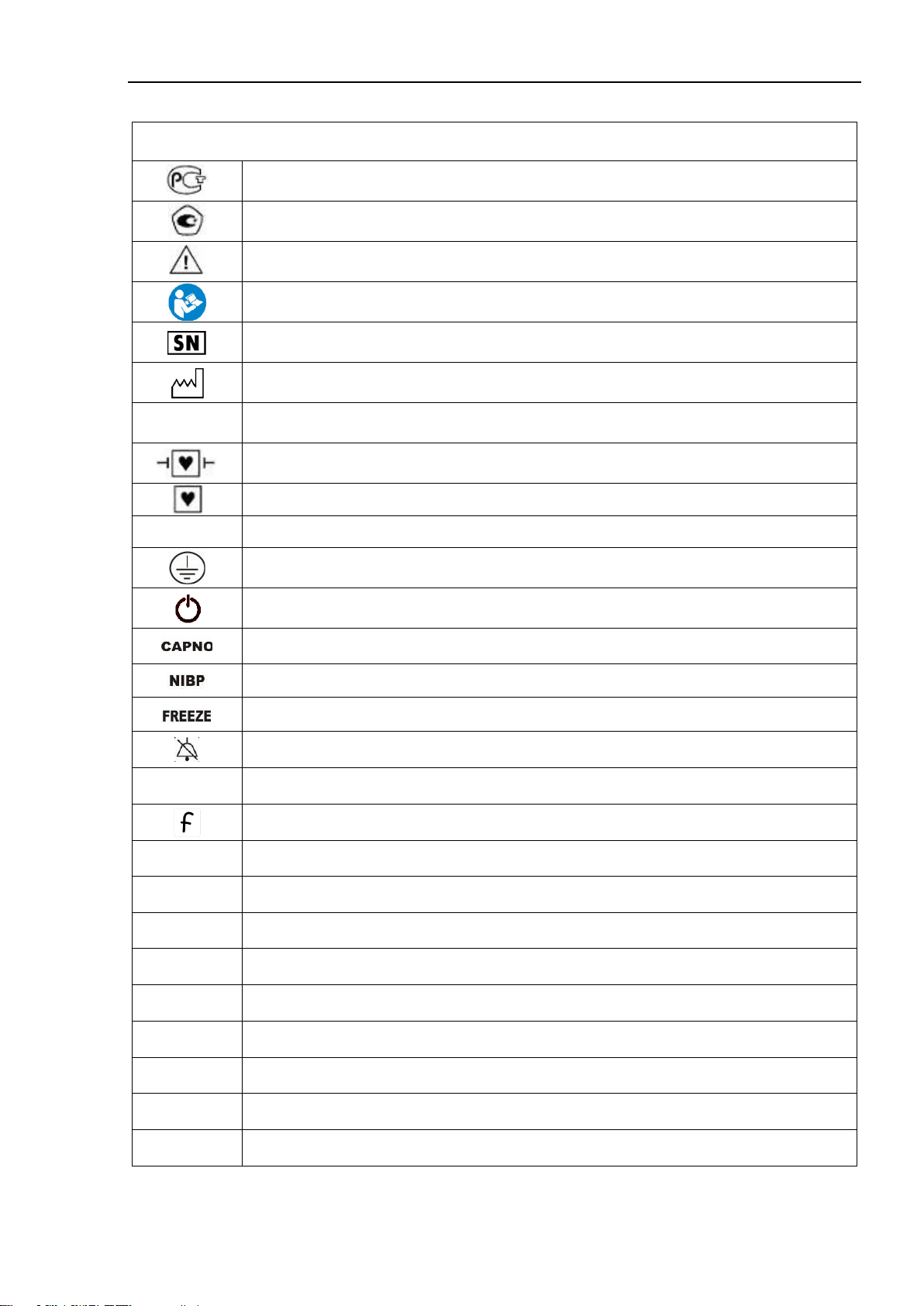
1.1.5. Symbols and Marks
Symbols, icons and marks used on the device housing
Russian Conformity mark
Type approval mark (measurement means according legislation of the Russian Fed-
eration)
ATTENTION, refer to the operating documents!
Refer to the operating documents!
Serial number
Manufacturing date
IP21
Degree of protection of the housing against penetration of water and solid particles
Part with CF defibrillator protection type
CF-type of device
~
Alternating current
Protective earth
Device on / off button
Capnometer activation button
Activation button of non-invasive blood pressure single measurement
Button to stop ("freeze") curves on the screen
Alarm silence for 2 minutes
123
Button for on / off mode "Large numbers"
F- button (programmable function)
IBP1
Port for the transducer of the 1st IBP channel
IBP2
Port for the transducer of the 2nd IBP channel
T1
Port for the sensor of the 1st temperature channel
T2
Port for the sensor of the 2nd temperature channel
NIBP
Connector for the cuff of the NIBP channel
SpO2
Saturation sensor port
ECG
Patient cable (ECG) connector
СО2/О2/AG
Connection of the multigas sampling line
Gas Exaust
Exaust of the capnometry channel sample
1.1 Introduction
12
Infoport
CAPNO
MGA
“Infoports” for mainstream CO2sensor, depth of anesthesia module
Ethernet
Connector to a local computer network
USB
Port for USB Flash memory devices
POWER
Device power supply LED
BAT
Charger and internal battery warning LED
OPEN
Built-in thermal printer cover latch
POWER
Power supply LED for built-in thermal printer
ERROR
LED for no paper or loose cover of the built-in thermal printer
12V
Connector for external DC-source, option
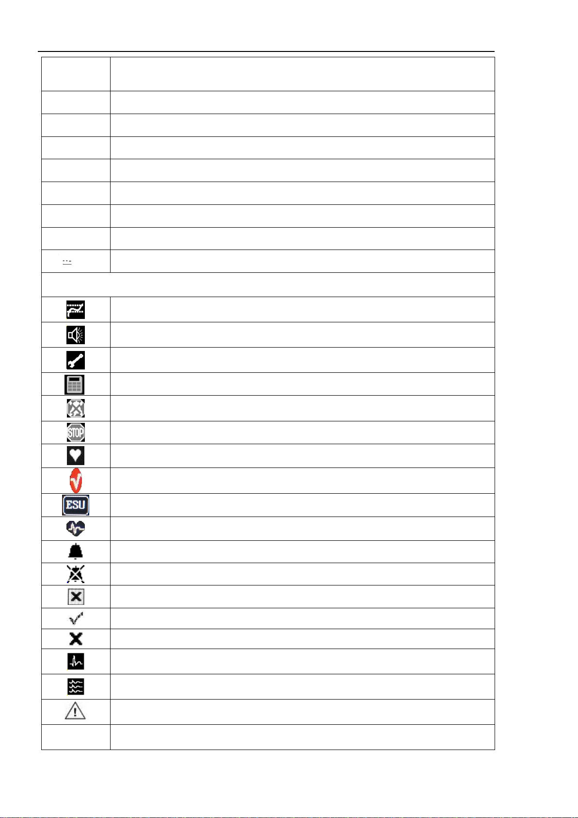
Symbols on the display
Trend window
Alarm sound window
Settings of general parameters
Calculator window
Silence of all alarms
Stopping graphs on the screen
HR signal source
Pulse oximetry Masimo SET® technology, optional
“Operating room” mode on/ off for the ECG-channel
Enable / disable pacemaker detection, optional
Audible alarm for this channel is enabled
Audible alarm for this channel is disabled
Exit the menu (close the window)
The function is enabled
Thefunction is disabled
Single waveform display mode in ECG window
Three waveform display mode in the ECG window
Arrhythmia analysis window
Nrm, S12
Lead synthesis window

1.1 Introduction
13
Reset to the factory settings
Start NIBP measurement
Stop NIBP measurement
Trends in a graphical form
Trends in a table form
Curve fragments window
Switch the trend scale (figure - current scale)
Button for moving along the trends or selecting the serial number of the recorded frag-
ment of the curves at the review
Button for moving page-by page
Start / cancel printing on a thermal printer (in the tabular trend window and in the wave-
form fragments window)
The color of the paper on the icon: white - the printer is ready, yellow - the printer is
busy, red - no paper in the printer
Pulse perfusion bar
ECG scale bar
Battery (fill level is proportional to energy, green when charging, yellow when discharg-
ing)
Zero calibration of the IBP channel and the sidestream capnometry channel
Manual / automatic input of the parameter in the calculator
Calibration of the touch panel
Symbols used on the installation equipment
Symbols warning of the danger of overturning (see p. 1.2.3)

1.1 Introduction
14
1.1.6. General Specifications
No.
Parameter
Description
1.
General
1.1
Intended use
Multiparameter patient monitor for the
long-term and continuous monitoring of
the vital functions of the patient.
1.2
Operation modes (patient groups)
Adult, pediatric, neonatal
1.3
AC power
220 ± 22 V / 50 Hz
1.4
Operation from a fully charged built-in battery
At least 120 min
1.5
Battery charge
Automatic
1.6
Built-in battery (option 1):
- type
- voltage
- capacity
Built-in battery (option 2):
- type
- voltage
- capacity
Pb
12 V
5000 mAh
Li-Ion
12±1.2 V
6600 mAh
1.7
Weight of the device (with built-in battery and power
supply)
<7.5 kg
1.8
Dimensions of the device housing, W x H x D:
370х360х200 mm
1.9
Display:- type
- diagonal size
- resolution (number of pixels horizontally and verti-
cally)
TFT, color touchscreen
15"
1024х768 pixels
1.10
Infoport for connecting of external modules
available
1.11
Operation with a centralized monitoring system with sim-
ultaneous connection of monitors
up to 32
1.12
Operation with a centralized monitoring system via radio
channel
optional
1.13
Connection of USB-flash
available
1.14
Maximum number of simultaneously displayed graphic
curves
8
1.15
Calculators
- drug dose calculator and titration table
- hemodynamic calculator
- oxygenation calculator
- ventilation calculator
- calculator of the kidney function
optional
1.16
Transportation
Top handle
1.17
Average service life
10 years
1.18
Standard service life
10 years
2.
Registered parameters
2.1
Cardiac activity (ECG / HR), ST-segment analysis
available
2.2
Pulse oximetry of peripheral circulation (PPG) and arteri-
al blood oxygenation (SpO2), pulse rate (PR)
available
2.3
Non-invasive blood pressure measurement (NIBP) –
SysAD, DiaAD, MapAD
available

1.1 Introduction
15
2.4
Continuous non-invasive blood pressure measurement
(cNIBP)–SysAD, DiaAD, MapAD, PWTT
available
2.5
Monitoring of central hemodynamics parameters by the
volume compression oscillometry: non-invasive meas-
urement of cardiac output (CO), stroke volume (SV), sys-
temic vascular resistance (SVR) with the calculation of a
number of related parameters
available
2.6
Temperature (T), skin and central, 2 channels
available
2.7
Respiratory impedance (RR / Respirogram)
available
2.8
Invasive blood pressure (IBP), 2 channels
optional
2.9
Sidestream capnography (capnogram, EtCO2, FiCO2)
optional
2.10
Oxymetry: oxygen concentration in inhaled / exhaled air
(FiO2, EtO2).
optional
2.11
Mainstream capnography (capnogram, EtCO2, FiCO2)
optional
2.12
Gas analysis of the gas inhaled / exhaled by the patient:
- concentration of anesthetics: halothane (Hal), enflu-
rane (Enf), isoflurane (Iso), sevoflurane (Sev), desflu-
rane (Des) in the inspiration (FiA1, FiA2) and expiration
(EtA1, EtA2);
- concentration of СО2, О2, N2O in the inspiration (Fi-
CO2, FiO2, FiN2O) and expiration (EtCO2, EtO2, ЕtN2О)
- capnogram, respiratory rate
optional
2.13
Depth of anesthesia evaluation
optional
2.14
Evaluation of respiratory mechanics parameters
optional
2.15
Non-invasive monitoring of the patient's metabolic needs
optional
3.
ECG channel
3.1
Leads
I, II, III, aVL, aVR, AvF, V1 - V6
3.2
Synthesized 12-channel ECG derived from 5 electrodes
available
3.3
Simultaneous displaying of any curves from 12 registered
ECG leads
3
3.4
Selecting of combination of monitored ECG leads
At user’s choice
3.5
Scaling of ECG curve
Manual and automatic
3.6
Displaying of digital parameters: HR, ST-segment offset,
HR alarm limits
available
3.7
Heart rate measurement range (HR)
0 - 350 1/min
3.8
Graphical and digital displaying of the ST-segment offset
relative to the isoline for all leads in the range, mm
-10…+10 mm
-1…+1 mV
3.9
Sweep speed
12.5; 25; 50 mm/sec
3.10
ESU and defibrillator protection
available
3.11
Continious displaying of cardiointervalogram (rhythmo-
cardiogram) and histogram of the distribution of cardioin-
tervals
available
3.12
Analysis and automatic recognition of arrhythmias
More than 18
3.13
HR correction at detection of pace maker pulse
Automatic
3.14
Detection range of QRS-complex width
4 - 84 ms

1.1 Introduction
16
3.15
Detection range of QRS-complex amplitude
0.05 - 10 mV
4.
Pulse oximetry channel
4.1
Displaying of pulse rate, perfusion, SpO2
Digital
4.2
Displaying of the photoplethysmogram
Continious
4.3
Scaling of the photoplethysmogram
Automatic
4.4
SpO2 indication range
10 - 100 %
4.5
SpO2 measurement range
70 - 100 %
4.6
Absolute accuracy of SpО2measurement
±2 %
4.7
Measurement range of pulse rate (PR)
15 - 350 bpm
4.8
Measurement range of pulse rate by Masimo (PR)
25 –240 bpm
4.9
Pulse rate accuracy
± 1 bpm
5.
Thermometry channel
5.1
Number of channels
2
5.2
Measurement principle
Thermistor
5.3
Displaying of temperature, including temperature differ-
ence of 2 channels
Digital
5.4
Temperature measurement range
0 - 50 °С
5.5
Temperature measurement accuracy
± 0.1°С
5.6
Type of sensors
Surface,
intracavitary (optional)
6.
Non-invasive blood pressure measurement
6.1
Measurement principle
Combined, with a preliminary meas-
urement at the phase of compression
(adult)
Oscillometric (pediatric, neonatal)
6.2
Digital displaying of arterial pressure
Systolic,
diastolic,
mean
6.3
Arterial pressure measurement range:
- adult mode
- pediatric mode
- neonatal mode
0 - 300 mmHg
10 - 200 mmHg
10 - 150 mmHg
6.4
Arterial pressure measurement accuracy
Up to ±3 mmHg
6.5
Average time of arterial pressure measurement:
- adult mode
- pediatric mode
- neonatal mode
Up to 30 sec
Up to 25 sec
Up to 25 sec
6.6
Measurement mode
Adult, pediatric, neonatal
Automatic, manual
6.7
Range of time intervals for automatic measurement
1 - 240 min,
with increment 1 min

1.1 Introduction
17
7.
Non-invasive monitoring of cardiac output (channel
of the central hemodynamics)
7.1
Measurement method - volumetric compression oscil-
lometry
Available
7.2
Measured parameters:
-SV –stroke volume
-СО –cardiac output
Calculated parameters:
-CI –cardiac index,
-SI –stroke index,
-SVR –systemic vascular resistance,
-SVRI –systemic vascular resistance index,
-SVI –stroke volume index,
-LCW –left ventricular work,
-LCWI –left ventricular work index,
-LSW –left ventricular stroke work,
-LSP –left ventricular stroke power,
-LSPI –left ventricular stroke power index,
-VSV –volume stroke velocity.
10 - 250 ml
1.0 - 20 lpm
Available
Available
Available
Available
Available
Available
Available
Available
Available
Available
Available
7.3
Adjustable measurement cycle time
1 to 240 min,
with an adjustment step of 1 min
8.
cNIBP channel (continuous non-invasive blood pres-
sure measurement)
8.1
Pulse wave transit time measurement (PWTT)
Continuous
8.2
Display of PWTT-determined diastolic, systolic and mean
BP
Continuous
8.3
Calibration
Automatic by oscillometric method en-
suring measurement accuracy for a
specific patient
8.4
cNIBP calibration threshold
Adaptive (automatic) and fixed (user-
defined)
9.
Impedance method of respiration parameters meas-
urement
9.1
Measurement principle
Measurement of impedance between
ECG electrodes
9.2
Displaying of respirogram
Continuous
9.3
Respiratory rate measurement range
5 - 160 bpm
9.4
Respiratory rate measurement accuracy
±3 bpm
9.5
Apnea alarm
Available
10.
Invasive blood pressure measurement channel (IBP)
10.1
Number of channels
2
10.2
Arterial pressure sensor:
Sensitivity
5 (mV / V / mmHg)
10.3
Impedance range
300 - 3000 Ohm
10.4
Digital displaying of arterial pressure
systolic, diastolic, mean

1.1 Introduction
18
10.5
Types (markers) of the measured pressure:
ART (Arterial blood pressure),
PA (Pulmonary artery pressure),
CVP (Central venous pressure),
ICP (Intracranial pressure)
RAP (Right atrial pressure),
LAP (Left atrial pressure)
RVP (Right ventricular pressure)
UA (Umbilical arterial pressure)
10.6
Invasive pressure measurement range:
-50… - 300 mmHg
10.7
Resolution
1 mmHg
10.8
Invasive pressure measurement accuracy:
- absolute in the range -50 - 100 mmHg
- relative in the range 100 - 300 mmHg
±2 mmHg
±2 %
10.9
Displaying of pulsation frequency at IBP curve
Available
10.10
Zero offset compensation range at invasive pressure
measurement
±100 mmHg
11.
Sidestream capnometry
optional
11.1
Method of measurement
Sidestream analysis
11.2
Laser capnometry method that does not require periodic
calibrations with reference gases
Available
11.3
Sample drying system
Does not require the lines with the mois-
ture absorber
11.4
Self-cleaning mode of the measuring line and measuring
cuvette
Automatic, when moisture appears in
the cuvette
11.5
Compensation for the nitrous oxide influence on the
measured CO2concentration
Manual
11.6
Measurement range
0 - 15 % or 0 - 115 mmHg
11.7
Display mode of concentration in % or partial pressure in
mmHg
Available
11.8
Measurement error of CO2concentration:
- absolute in the range 0 - 5%
- relative in the range of 5.1 - 10%
- relative in the range of 10.1 - 15%
±0,2 %
±4 %
±6 %
11.9
Displaying of capnogram, EtCO2, EiCO2, respiration rate,
alarm thresholds
Available
11.10
Capnogram sweep speed adjustment
2 sweep speeds
11.11
Adjustable alarm thresholds by EtCO2and FiCO2
Available
12.
Oxymetry channel
optional
12.1
Measurement range of О2concentration
0 - 100 %
12.2
Absolute error of О2 concentration measurement
±2 %
12.3
Displaying of О2concentration in the inspired / expired
air (FiO2 / EtO2)
Available
13.
Mainstream capnography
Optional
13.1
Measurement principle
Mainstream capnography
13.2
Displaying of capnogram, speed and scale of capnogram
at user’s choice
Available

1.1 Introduction
19
13.3
Measurement range:
- СО2concentration
- СО2partial pressure
0 - 15 %
0 - 115 mmHg
13.4
Measurement accuracy of СО2concentration:
- absolute in the range 0 - 5 %
- relative in the range 5,1 - 10 %
- relative in the range 10,1 - 15 %
(CО2 partial pressure:
- absolute in the range 0 - 40 mmHg
- relative in the range 41 - 80 mmHg
- relative in the range 81 - 115 mmHg)
±0.2 %
±4 %
±6 %
±1.5 mmHg
±4 %
±6 %
13.5
Respiration rate indication range
0 - 160 bpm
14.
Multigas channel
Optional
14.1
Monitored gases:
Carbon dioxide (СО2),
Nitrous oxide (N2O),
Oxygen (O2)
14.2
Monitored anesthetics:
Halothane (Hal),
enflurane (Enf),
isoflurane (Iso),
sevoflurane (Sev),
desflurane (Des)
14.3
Monitoring of СО2:
- CO2concentration measurement range
- CO2partial pressure measurement range
- maintaining the accuracy of measurements of CO2con-
centration in the presence of associated gases (N2O,
anesthetics)
- display of digital parameters: EtCO2, FiCO2, respiratory
rate, alarm thresholds
0 - 15 %
0 - 115 mmHg
Available
Available
14.4
Monitoring of О2:
- О2 concentration measurement range
0 - 100 %
14.5
N2Оconcentration measurement range
0 - 100 %
14.6
Range of the anesthetics monitoring:
- halothane (Hal), enflurane (Enf), isoflurane (Iso)
- sevoflurane (Sev)
- desflurane (Des)
0 - 5 %
0 - 8 %
0 - 18 %
14.7
Simultaneous graphical display of curves for one / two
gases and any anesthetic agent of the user's choice
Available
14.8
Calculation of the MAC value for anesthetics
Available
15.
Depth of anesthesia and sedation channel
Optional
15.1
Method of measurement
Electroencephalogram (EEG) analysis
15.2
Displayed digital parameters:
Brain activity index (AI)
Suppression rate (SR)
Signal quality index (SQI)
Electromyographic component level (EMG)
0 - 100 rel. units
0 - 100 %
0 - 100 %
0 - 100 dB

1.1 Introduction
20
15.3
Displayed graphic parameters:
EEG curve in one measured lead with adjustment of
the window size (5, 10, 30, 60 s) and EEG scale (10 -
1000 mV)
Trends of brain activity index and EMG level with ad-
justable trend length (5, 10, 30, 60 min)
The level of high-frequency and mains (50 Hz) inter-
ference
The impedance of electrodes (3 values)
Graphical representation of SR, SQI parameters in
the form of a bar graph
Available
Available
Available
Available
Available
15.4
Electrode impedance measurement
In automatic (every 6 minutes) and
manual mode
15.5
Saving the trend of the brain activity index in the nonvola-
tile memory of the device
240 hours
16.
Measurement channel of the respiratory mechanics
parameters
Optional
16.1
Monitored parameters:
-PIP –peak inspiratory pressure
-PEEP –positive end-expiratory pressure
-Ve–volume of the last to the given moment exhala-
tion
-MVe–minute ventilation volume
Available
Available
Available
Available
16.2
Displaying of curves of flow, volume and pressure in the
breathing circuit
Automatic
17.
Patient metabolic needs monitoring channel
Optional
17.1
Monitored parameters:
VO2–oxygen consumption
VCO2–carbon dioxide elimination
REE –resting energy expenditure
RQ –respiratory quotient
Available
Available
Available
Available
17.2
MOV (minute volume) input mode
Automatic (if equipped with a respiratory
mechanics module) or manual
17.3
Recalculation of metabolic monitoring parameters
Automatic
18.
User interface
18.1
Display
TFT color touchscreen
18.2
Fast access buttons
Available
18.3
Regulator for quick change of parameters
Encoder
18.4
“Large numbers” mode
Available
18.5
“Freezing” mode
Available
18.6
Indication of pulse rate
Sound
18.7
System of explanatory text messages
Available
19.
Alarms
19.1
Alarm of measured parameters
3 levels of sound and visual alarms (dif-
ferent colors)
19.2
Background color depending on the alarm priority of all
measured parameters
Available
19.3
Setting of the volume of the sound alarm
At least 10 gradations
Table of contents
Other Treaton Medical Equipment manuals

Popular Medical Equipment manuals by other brands


Sedeo
Sedeo Pro+ 1010977 Assembly instructions

Joerns
Joerns Oxford Standing Harness User instruction manual

Insportline
Insportline Greod IN 19895 user manual

IGEA
IGEA Cliniporator EPS02 user manual

Atmos
Atmos A 161 Battery Series operating instructions

Owandy Radiology
Owandy Radiology i-max touch Service manual

medotech
medotech GRINDCARE 3.0 user manual

TSI Incorporated
TSI Incorporated Certifier FA Plus Operator's manual

Welcare
Welcare HEALTH WPC100 instruction manual

DJO
DJO Aircast AIRSELECT STANDARD Patient guide

Dermlite
Dermlite carbon manual

Polymer Technology Systems
Polymer Technology Systems CardioChek P-A user guide