Treaton MV200 User manual

4th edition 12/2016
I
IN
NT
TE
EN
NS
SI
IV
VE
E
C
CA
AR
RE
E
V
VE
EN
NT
TI
IL
LA
AT
TO
OR
R
MV200
U
US
SE
ER
R
M
MA
AN
NU
UA
AL
L
TESM.941144.001-01 UM
2
nd
edition, 10/2019


CONTENT
1 INTRODUCTION ................................................................................................. 1-1
1.1 Intended use..................................................................................................... 1-1
1.2 General guidance ............................................................................................. 1-4
1.3 Symbols and references................................................................................... 1-5
1.4 Information about resource of the main functional units of the device .............. 1-8
1.5 Revision history ................................................................................................ 1-8
2 DESCRIPTION OF DEVICE................................................................................ 2-1
2.1 Basic parameters and characteristics............................................................... 2-1
2.2 Configuration of device ..................................................................................... 2-5
2.3 Front panel ....................................................................................................... 2-9
2.4 Rear panel ........................................................................................................ 2-11
2.5 Transport cart (mobile trolley)........................................................................... 2-12
3 PREPARING FOR OPERATION ........................................................................ 3-1
3.1 Operating conditions......................................................................................... 3-1
3.2 Safety precautions............................................................................................ 3-1
3.3 Preparing for operation..................................................................................... 3-4
3.3.1 Preparing of the device and accessories .............................................. 3-4
3.3.2 Installation of the electronic unit and the supporting arm ...................... 3-4
3.3.3 Installation of humidifier......................................................................... 3-6
3.3.4 Assembling of the breathing circuit ....................................................... 3-7
3.3.5 Connecting to the oxygen source.......................................................... 3-11
3.4 Device turning on and off.................................................................................. 3-14
3.5 Cleaning, disinfection and sterilization.............................................................. 3-16
3.5.1 Cleaning, disinfection of external parts and non-sterilized components 3-16
3.5.2 Reprocessing of sterilized components................................................. 3-17
4 DEVICE CONTROL ............................................................................................ 4-1
4.1 Main features of device..................................................................................... 4-1
4.2 Reserve power supply ...................................................................................... 4-3
4.2.1 Built-in accumulator............................................................................... 4-3
4.2.2 Features of reserve power supply operation ......................................... 4-3
4.3 Controls ............................................................................................................ 4-5
4.4 Starting window. Beginning of ventilation ......................................................... 4-6
4.4.1 Starting window..................................................................................... 4-6

4.4.2 Window of associated parameters.........................................................4-7
4.4.3 Automatic calculation of initial ventilation parameters............................4-7
4.4.4 Initial alarm settings...............................................................................4-9
4.4.5 Calibration procedure before the beginning of operation.......................4-9
4.5 Main window .....................................................................................................4-11
4.6 Main menu ........................................................................................................4-14
4.7 Setting of ventilation modes and parameters .................................................... 4-15
4.7.1 Ventilation mode selection.....................................................................4-15
4.7.2 Changing of parameters. Conflict of parameters ...................................4-16
4.7.3 View of parameter setting line in the different ventilation modes...........4-18
4.7.4 Description of ventilation parameters..................................................... 4-19
4.8 Menu of general ventilation parameters setting ................................................4-22
4.8.1 Description of general ventilation parameters .....................................4-22
4.8.2 Menu of apnea parameters .................................................................4-24
4.8.3 Menu of iSV mode parameters............................................................4-25
4.8.4 Menu of Pmax, Tinsp limits .................................................................4-25
4.9 Setting of the type of inspiration trigger.............................................................4-26
4.10 Automatic calibration of the oxygen sensor.....................................................4-27
4.11 Additional functions.........................................................................................4-28
4.11.1 Alveolar recruitment maneuver............................................................4-28
4.11.2 Oxygenation ........................................................................................4-30
4.11.3 Suction.................................................................................................4-30
4.11.4 Standby mode .....................................................................................4-31
4.11.5 Leak compensation..............................................................................4-32
4.11.6 Manual breath (manual ventilation)......................................................4-33
4.11.7 Screen lock..........................................................................................4-34
4.11.8 "Freezing" / analysis of graphs ............................................................4-35
4.11.9 Display brightness control....................................................................4-35
4.12 Display settings menu.....................................................................................4-36
4.12.1 Graph setting menu ........................................................................... 4-36
4.12.2 Menu of settings of measuring parameter blocks ..............................4-39
4.13 Menu of view of trends and alarm log .............................................................4-40
4.14 Alarm settings menu .......................................................................................4-44
4.15 Volume settings menu.....................................................................................4-46
4.16 Service menu ..................................................................................................4-47

4.16.1 Function of service menu parameters ................................................. 4-47
4.16.2 Calibration of FiO
2
sensor, O
2
sensor of metabolism measurement
module .......................................................................................................... 4-51
4.16.3 Expiratory flow sensor calibration........................................................ 4-53
4.16.4 Selection of flow correction conditions on the inspiration and
the expiration.................................................................................................. 4-54
4.16.5 Breathing circuit calibration ................................................................. 4-54
4.17 Alarms ............................................................................................................ 4-57
4.17.1 High priority alarms ............................................................................. 4-59
4.17.2 Medium priority alarms ........................................................................ 4-61
4.17.3 Low priority alarms .............................................................................. 4-63
4.17.4 Informational messages ...................................................................... 4-65
4.17.5 Special alarms of iSV mode ................................................................ 4-66
4.17.6 Emergency and technical failure modes.............................................. 4-66
4.18 Extended respiratory monitoring..................................................................... 4-69
4.19 Features of using antibacterial and heat and moisture exchange filters ......... 4-71
4.20 Nebulizer ........................................................................................................ 4-72
4.21 "Open valve" function ..................................................................................... 4-75
5 OPTIONAL FEATURES OF THE DEVICE ......................................................... 5-1
5.1 Mainstream CO
2
sensor (capnometer) ............................................................. 5-1
5.2 Volume capnometry.......................................................................................... 5-5
5.3 Cardiac output by Fick ...................................................................................... 5-7
5.4 Pulse oximetry module ..................................................................................... 5-9
5.5 Metabolism measurement module.................................................................... 5-14
5.6 Compensation of endotracheal tube resistance................................................ 5-19
5.7 “Auxiliary external pressure” function................................................................ 5-20
5.8 Operating with low pressure oxygen source ..................................................... 5-24
5.9 Data exchange with computer .......................................................................... 5-25
6 MAINTENANCE OF THE DEVICE...................................................................... 6-1
6.1 Maintenance schedule...................................................................................... 6-1
6.2 Visual inspection and test of controls ............................................................... 6-2
6.3 Cleaning and replacement of fan filters ............................................................ 6-2
6.4 Check of sealing gaskets.................................................................................. 6-2
6.5 Check of the filter-regulator .............................................................................. 6-3
6.6 Check of the expiration valve............................................................................ 6-3

6.7 Check and calibration of the FiO
2
oxygen sensors and the metabolism
measurement module .............................................................................................6-4
6.8 Check of built-in accumulator............................................................................6-5
6.9 Check of the set tidal volume ............................................................................6-6
6.10 Check of PEEP ...............................................................................................6-6
6.11Check and calibration of mainstream CO
2
sensor............................................6-6
7 TROUBLESHOOTING.........................................................................................7-1
8 TRANSPORTATION............................................................................................10-1
9 STORAGE ...........................................................................................................10-1
10 DISPOSAL.........................................................................................................10-1
11 WARRANTY ......................................................................................................11-1
11.1 Warranty .........................................................................................................11-1
11.2 Guarantee procedure......................................................................................11-2
11.3 Address for notes and complaints...................................................................11-2
12 CERTIFICATE OF ACCEPTANCE ...................................................................12-1
13 COMMISSION DATE MARK .............................................................................12-1
14 MAINTENANCE AND REPAIR DATA ..............................................................14-1
14.1 Device maintenance (MA)...............................................................................14-1
14.2 Device repair...................................................................................................14-1
APPENDIX 1 DESCRIPTION OF VENTILATION MODES .................................... App.1-1
Appendix 1.1 Description of CMV / VCV mode.......................................................App.1-1
Appendix 1.2 Description of CMV / PCV mode.......................................................App.1-2
Appendix 1.3 Description of SIMV/VC, SIMV/PC, SIMV/DC modes .......................App.1-3
Appendix 1.4 Description of CPAP+PS mode.........................................................App.1-4
Appendix 1.5 Description of BiSTEP mode.............................................................App.1-5
Appendix 1.6 Description of NIV mode ...................................................................App.1-8
Appendix 1.7 Description of APRV mode ...............................................................App.1-9
Appendix 1.8 Description of PCV-VG mode............................................................App.1-10
Appendix 1.9 Description of APNEA mode ............................................................App.1-11
Appendix 1.10 Description of the intelligent adaptive ventilation iSV ......................App.1-12
Appendix 1.10.1 Function of iSV mode. General description ......................App.1-12
Appendix 1.10.2 Assessment of respiratory rate ..........................................App.1-13
Appendix 1.10.3 Assessment of the tidal volume .........................................App.1-13
Appendix 1.10.4 Limits of the safe iSV ventilation. General concepts..........App.1-13
Appendix 1.10.5 I:E ratio, medical aspects................................................... App.1-14

Appendix 1.10.6 Calculation of the respiratory cycle phases (I:E) ............... App.1-14
Appendix 1.10.7 Start of iSV mode .............................................................. App.1-15
Appendix 1.10.8 General description of the iSV pattern mode adjustment
algorithm ...................................................................................................... App.1-16
Appendix 1.10.9 Function of MV adaptation ................................................ App.1-17
Appendix 1.10.10 Pmin parameter............................................................... App.1-17
Appendix 1.11 Selection of ventilation modes at the patient's disturbance and
cough ........................................................................................................... App.1-18
APPENDIX 2 METHODS OF DETERMINING PARAMETERS ............................. App.2-1
Appendix 2.1 Compliance and resistance............................................................... App.2-1
Appendix 2.2 AutoPEEP......................................................................................... App.2-1
Appendix 2.3 Mean pressure in the circuit for the respiratory cycle (Pmean)......... App.2-2
Appendix 2.4 Time constant of the respiratory tract (τexp, τinsp)........................... App.2-3
Appendix 2.5 Work of breathing (WOB) ................................................................. App.2-4
Appendix 2.6 Rapid shallow breathing index (RSBI) .............................................. App.2-5
Appendix 2.7 Stress index (SI) ............................................................................... App.2-5
Appendix 2.9 Ideal body weight of the patient (IBW) .............................................. App.2-8
APPENDIX 3 ELECTROMAGNETIC ENVIRONMENT.......................................... App.3-1
APPENDIX 4 PNEUMATIC SCHEME OF VENTILATOR...................................... App.4-1
APPENDIX 5 TECHNICAL MALFUNCTION AND EVENTS ................................. App.5-1
Appendix 5.1 Technical malfunction ....................................................................... App.5-1
Appendix 5.2 Technical messages ......................................................................... App.5-2
APPENDIX 6 DELIVERY SET .............................................................................. App.6-1
APPENDIX 7 ADDITIONAL PARAMETERS AND CHARACTERISTICS ............. App.7-1
GLOSSARY ........................................................................................................... Gl.-1


1.1 Intended use
1-1
1
INTRODUCTION
1.1 Intended use
Intensive care ventilator MV200 (hereinafter – device, ventilator) is intended for carrying out
controlled and assisted artificial ventilation of lungs for all patient groups with tidal volume from
10 ml dependent on artificial ventilation in resuscitation units, surgery and intensive care de-
partments of professional medical facilities, and also at transportation within professional medi-
cal facilities.
Ventilation modes of device are in detail described in it. 4.1 and the Appendix 1.
Figure 1.1 - Appearance of the device
Simplicity of control, functional design of the device, graphical display module allowing to set it
under the optimum angle provide convenience of operation.
The device is equipped with the built-in respiratory mixture flow generator (analogue of the tur-
bine) and does not need sources of the compressed air. For connection to the high pressure
oxygen line the device is equipped with the pneumatic socket. The built-in oxygen sensor
measures oxygen concentration in the respiratory mixture and allows controlling operation of
the air-oxygen mixer of the device.
The device can have the version allowing operation with sources of low pressure oxygen. In this
case it has the special low pressure oxygen input.
At emergency case (absence of oxygen) the device provides ventilation only with air. Due to its
design the device can operate even at the minimum pressure in oxygen system of the hospital,
taking away all possible oxygen from the line. Therefore deviations in FiO
2
regulation are possi-
ble.

1.1 Intended use
1-2
The device is equipped with the touch color display 12.1” where measured data in the form of
figures and graphs (waveforms) and all information necessary for the ventilation control are dis-
played.
Special fastening of the display on the electronic unit surface allows to change the viewing an-
gle and fully fold the display (so the operating surface of the display lies on the plane of the
base unit) during storage and transportation of the device in order to avoid mechanical damage.
Controls of the device are the rotated regulator (encoder), the touch screen and functional con-
trol buttons. They provide fast and convenient access to the control parameters, registered
monitoring information (trends). Control buttons are made using touch technology (“touch-
screen”). In particular, set parameters of the current mode of ventilation are touch control but-
tons, they become active by pressing.
To avoid the accidental or inadvertent change of ventilation parameters in the device are ap-
plied:
•The three-stage scheme of applying of changes (activation, change, and confirmation). It is
necessary to confirm with special action application of the changed parameter;
•Function of the screen blocking that can be operatively switched on by the user.
For warming and moistening of the respiratory mixture the humidifier with the set of consu-
mables is needed. Please pay attention that humidifier is not included in the basic delivery set.
If necessary artificial ventilation of lungs can be carried out with the heat and moisture exchang-
ing filter that also is the part of the device delivery kit. The temperature of the respiratory mixture
is displayed on the humidifier; ways of displaying depends on the humidifier model.
The delivery kit of the device can contain adult, child reusable and/or disposable breathing cir-
cuits.
The device is equipped with the expiration valve with the electromagnetic mechanism operated
by the ventilation controller. The expiration valve has the small lag effect that does not exceed 5
ms and provides necessary dynamics of pressure maintenance in the breathing circuit. The ex-
piration valve has the removable part containing flow sensor and transmitting system of meas-
ured pressure to the device.
The membrane and the removable part of the expiration valve with the flow sensor have direct
contact with air exhaled by the patient, except the breaching circuit. These elements shall be
sterilized before using on the new patient. The membrane and the expiration valve are made
from the materials allowing sterilization by autoclaving.
The device kit contains the circuit holder (supporting arm) that provides a big range of attitudes
and allows to place conveniently the breathing circuit.
The device can be equipped with the mainstream CO
2
sensor, its connection to the circuit is
made via the special airway adapter connected as close as possible to the endotracheal tube.
The device with the mainstream CO
2
sensor can have optional function of the volume capnome-
try. This function allows to measure amount of carbon dioxide exhaled by the patient, and also
to define volume of the functional dead space and volume of alveolar ventilation.
Optionally the device can be equipped with the built-in module of the metabolism parameters
assessment, operating on methods of the sidestream oximetry and mainstream capnometry.
The device can incorporate two oxygen sensors. One quite slow measures oxygen concentra-
tion in the inspiratory flow (always exists) and the second is special high-speed sensor for the
assessment of the oxygen concentrations gradient at the inspiration and the exhalations.
The device has function of the automatic calibration of the main oxygen sensor without stopping
ventilation. Also 2 precision flow sensors are used in addition for measurement and control of
concentration О
2
in the inhaled gas mixture.
Electrochemical oxygen sensor is used as the main.

1.1 Intended use
1-3
The high-speed oxygen sensor operates consistently with the sidestream oximetry module with
the same drained gas sample, and it measures the difference of oxygen concentrations in inspi-
ratory and expiratory phases of the respiratory cycle.
Pulse oximeter also can be the part of the device. In this case the delivery kit contains the pulse
oximetry sensor of clip type (or another on special order).
Flow and pressure sensors are placed inside the device and do not need any special lines for
the operation. Inspiratory flow sensors are separate for air and oxygen that allows managing
oxygen concentration independently of the technical condition of oxygen sensors. The expirato-
ry flow sensor is structurally placed in the expiration valve behind the membrane. Calibration of
the expiratory flow sensor is carried out without stopping of ventilation. Pressure measurement
in respiratory ways is made by means of two independent pressure sensors embedded in elec-
tronic unit.
The device can contain the additional pressure measurement channel where the measurement
catheter can be connected, for example, catheter for the pressure measurement in the trachea
or in the esophagus.
The transport cart (mobile trolley) with the handle for movement and five wheels are the part of
the basic kit. The wheels of the cart have clamps. Standard way of use of the device is installa-
tion of the electronic unit and the humidifier on the transport cart. However, operation without
the transport cart is also possible. The electronic unit of the device is equipped with handles for
its carrying, at removal from the transport cart.

1.2 General guidance
1-4
1.2 General guidance
The current User manual is a component of the device and the mandatory part of the delivery
set. This document is provided only for information purposes, it is prohibited to copy, reproduce,
translate it into other language, to keep in the information retrieval system, to transmit in any
form or by any means or to transform to a form suitable for storage on electronic data carriers
without the prior written permission of the manufacturer. Information contained in this document
can be changed without notice.
Before starting of operation with the device attentively read current manual. Remember that mi-
shandling can cause performance deterioration of the device, its malfunction and safety hazard
for the patient.
At malfunction or unstable operation of the device, firsty it is necessary to address to the list of
possible malfunctions and methods of their elimination (see Section 7), and also to appropriate
sections of the present User manual.
In the current User manual the following designations are used:
This information is necessary to know to avoid injuries of patient or per-
sonnel.
This information is necessary to know for proper and efficient use of the
device and to avoid its damage.
The Triton Electronic Systems Ltd. holds responsibility for reliability and operational characteris-
tics of the device only if:
•service and installation of the device are carried out by specialists of Triton Electronic Sys-
tems Ltd or personnel passed special training and authorized by Triton Electronic Systems
Ltd on carrying out of these works;
•the mains power meets the requirements of national standards;
•ventilator is used in accordance with current User Manual.
Reusable consumables have limited service life. Various operation conditions, cleaning, disin-
fection and sterilization can lead to the deterioration and the corresponding reduction of their
service life. At appearing of visible signs of deteriotation (cracks, deformation, decolouration,
paint detachment etc.) it is necessary to replace the consumables with the new.
Contacts:
Manufacturer
Triton Electronic Systems Ltd.
Legal address
Production site address
Customer service
Post address
Е-mail
Website
9 Shevchenko str., of. 217, Ekaterinburg, 620027, Russia
12/5 Sibirskiy Trakt str., Ekaterinburg, 620100, Russia
phone +7 (343) 304-60-51
P/b 522, Ekaterinburg, 620063, Russia
http://www.treat-on.com
Authorized Representative in EU
Wladimir Wollert
Otto-Selzer Straße 16, D-97340 Marktbreit, Germany
Tel.: +49 9332 5994095
E-mail: wladimir-[email protected]

1.3 Symbols and references
1-5
1.3 Symbols and references
The symbols used on the enclosure of the device
Marking of Conformity to European Medical Device Directive
Caution!
Refer to accompanying documents!
Applied part of ВF type
Applied part of Вtype
Mark of conformity of the Directive 2002/92/EG
Serial number
Date of manufacture
Manufacturer
Authorized representative in EU
IP 21
Type of enclosure protection from ingress of water and solid particles
General sign of prohibition
Alternative current
Mains power switch
Sound alarm pause button
The button calling the menu window, cancellation of parameter set, menu exit etc.
The button calling the menu of additional functions (nebulizer)
The button calling the delayed alarms log
Oxygen inlet, necessary operating pressure 0.15…0.6 MPa
Additional oxygen inlet for connection to the low-pressure oxygen source (optional)
Outlet of the exhausted gas mixture
Port for connection of the inspiratory line of the breathing circuit
Port for connection of the expiratory line of the breathing circuit
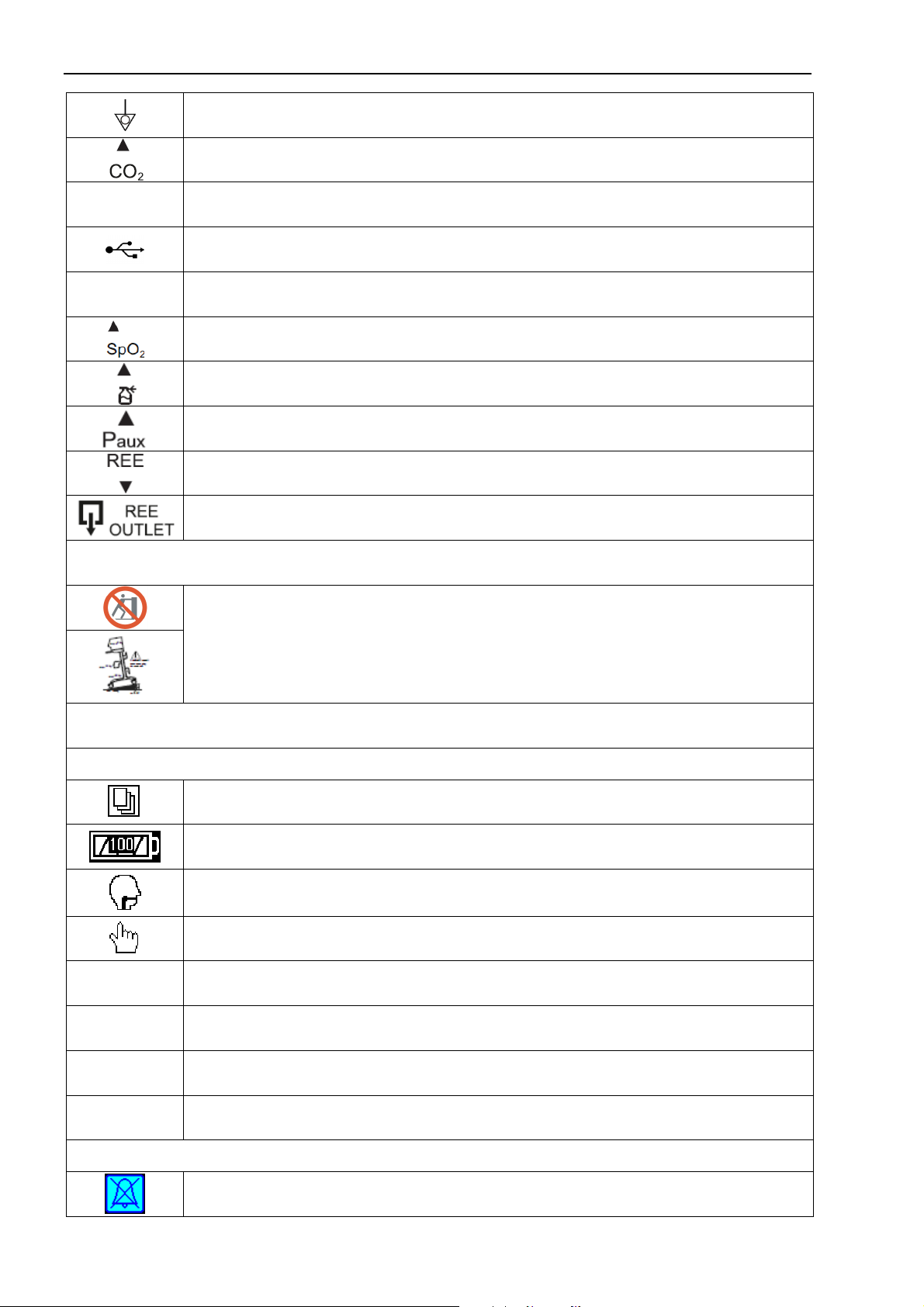
1.3 Symbols and references
1-6
Equipotentiality
Port for connection of the mainstream CO
2
sensor
Ethernet Connector for the local information network by the standard Ethernet protocol
Connector for USB Flash memory devices
T2.0AL/250V Mains power fuse
Connector for the pulse oximetry sensor
Connector for the pneumatic nebulizer
Port for connection of the catheter for auxiliary external pressure monitoring
Port for connection of water trap and sampling line of metabolism measurement module
Output port of metabolism measurement module (is used for elimination of the gas sam-
ple to the atmosphere)
Symbols on the transport cart
Symbols warning of the overturning danger (see p. 3.2)
Symbols and icons on the ventilator screen
General and patient symbols
Open/Close menu window button
Battery condition symbol (level of filling is proportional to the energy, green - at a charge,
yellow - at a discharge, red blinking - at the faulty accumulator)
Indicator of patient’s spontaneous inspiration attempts
Measurement of a compliance and resistance button
adult “Adult” type of patient
child “Child” type of patient
IBW Ideal body weight
ET (TST) Endotracheal (tracheostomy) type of tube
Icons
Sound alarm off

1.3 Symbols and references
1-7
Oxygenation
Standby mode
Alveolar recruitment maneuver
Suction
Leak compensation
Manual breath (manual ventilation)
“Freezing”/ analysis of graphs
Screen lock
Display brightness control
Graphs
Flow
Flow graph
iSV Graph of iSV mode
Paux Auxiliary external pressure graph
Paw Airway pressure graph
PCО
2
Capnogram
PО
2
Oxigram for operating with the metabolism measurement module (calculated as the dif-
ference FiO
2
- EtO
2
)
REF Reference loop
SpO
2
Photopletismogram
VCO
2
Volume capnography graph
Vol Volume waveform
V-F Volume/ Fow loop
V-P Volume/ Pressure loop
F-P Flow/ Pressure loop
V-Paux Volume / Auxiliary pressure loop

1.4 Information about resource of the main functional units of the device
1-8
1.4 Information about resource of the main functional units of the device
The device has the built-in flow generator providing its independence from sources of com-
pressed air. The design and completing units provide guaranteed operability of the built-in flow
generator during at least 40 000 operating hours, or during the whole period of operation of 10
years (the smallest parameter is chosen). Operability of the built-in flow generator is guaranteed
only at following operating and service conditions stated in the present document.
For the monitoring of oxygen concentration in the inhaled air the device has the built-in electro-
chemical oxygen sensor with the operation resource at least 10 thousand hours.
For the service control the device has the special operating time counter. After 6 000 operating
hours the message appears at the screen of the device “Carry out maintenance”. The engineer
who has carried out maintenance should enter the command in the service menu “Reset time
after maintenance” then the time counter will return to the starting position.
1.5 Revision history
Every version of User manual has its number and date of issue. Version number is changed
with the significant technical changes of the device. When issuing new version, date of version
is also changed. Insignificant amendments and additions that don’t influence on the modes,
functions and parameters of ventilator, don’t cause the change of version date.

2.1 Basic parameters and characteristics
2-1
2
DESCRIPTION OF DEVICE
2.1 Basic parameters and characteristics
No Parameter Value (description)
1
General features
1.1 Intended use
Controlled and assisted artifical ventilation
of lungs at the patients depending on
hardware ventilation in resuscitation units,
surgery and intensive care departments of
professional medical facilities, and also at
transportation within professional medical
facilities.
1.2 Modes of operation Adult, pediatric
1.3 Display Touch, color, 12.1 inches
1.4
Electrical power
Mains
Built-in accumulator
100 - 250 V, 50/60 Hz
10-27 V
1.5 Maximum power consumption not more than 300 VA
1.6 Operation mode setup time Maximum 15 sec
1.7 Time of full ventilation when powered on internal ac-
cumulator at mains power failure
Not less than 240 minutes at any ventilator
settings
1.8
Dimensions of enclosure, width хheight хdepth
electronic unit
electronic unit installed at the mobile trolley
maximum 450х450х650 mm
maximum 600х600х1450 mm
1.9
Weight
electronic unit
electronic unit installed at the mobile trolley
maximum 20 kg
maximum 35 kg
1.10
Input oxygen pressure Operation from a high pressure
oxygen sources 0.15 - 0.6 MPa (1.5 - 6 bar)
1.11
Operation from a low pressure oxygen sources 0 - 0.005 MPa (0 - 0.05 bar)
1.12
Accuracy of the mixer when regulating the oxygen
concentration in the gas mixture
- in the range 21-60%
- in the range 61-100%
3 %
6%
1.13
Trigger system of the device Flow and pressure triggers
1.14
Function of saving and viewing of trends of the main
monitoring parameters.
The duration of trend
Available
240 hours
1.15
Humidifier External: provide humidification and heat-
ing of respiratory gas mix
1.16
Nebulizer Built-in, pneumatic
Optional: external, ultrasonic micro-pump
1.17
The synchronization of the nebulizer with the begin-
ning of the patient’s inspiration Available
1.18
Noise level at operation of the device
Corrected sound power level
up to 43 dBA
up to 51 dBA
2
Ventilation modes
2.1
Continuous mandatory ventilation with the controlled
volume of inspiration (synchronized ventilation with
volume control)
CMV/VCV

2.1 Basic parameters and characteristics
2-2
No Parameter Value (description)
2.2
Continuous mandatory ventilation with the controlled
pressure of inspiration (synchronized ventilation with
pressure control)
CMV/PCV
2.3
Synchronized intermittent mandatory ventilation with
flow trigger or pressure trigger with volume control
with pressure support of spontaneous breaths (PS)
SIMV/VC
2.4
Synchronized intermittent mandatory ventilation with
flow trigger or pressure trigger with pressure control
with pressure support of spontaneous breaths (PS)
SIMV/PC
2.5
Synchronized intermittent mandatory ventilation with
flow trigger or pressure trigger with double control with
pressure support of spontaneous breaths (PS)
SIMV/DC
2.6
Spontaneous breathing with continuous positive air-
way pressure with pressure support of spontaneous
breaths (PS)
CPAP+PS
2.7
Spontaneous breathing with two levels of continuous
positive airway pressure with pressure support of
spontaneous breaths (PS)
BiSTEP
2.8 Airway pressure release ventilation APRV
2.9 Pressure controlled ventilation with guaranteed respi-
ratory volume PCV-VG
2.10 Non-invasive ventilation of lungs NIV
2.11 Intellectual support ventilation (option) iSV
2.12 Automatic backup ventilation mode in cases of pres-
sure and volume apnea. APNEA
3
Ventilation parameters
3.1
Tidal volume, Vt
Measuring accuracy :
In range 10-100 ml
In range 100-3000 ml
10 - 3000 ml
±(2+0.05Vt) ml abs
±8 % rel
3.2
Minute volume, MV 0 - 60 lpm
3.3
Rate of breathing / respiratory rate (controlled respira-
tory cycles), RB:
1 - 120 1/min
3.4
Frequency of mandatory breaths at synchronized in-
termittent assisted ventilation, RB 1 - 60 1/min
3.5
Waveform of the gas flow in the ventilation modes with
volume control, FormFlow Rectangular, descending
3.6
Periodic enhanced inspiration Available
3.7
I:E ratio 1:99 - 60:1
3.8
Plateau time, Tplat 0 - 5 s
0 - 70 % from inspiratory time
3.9
Support pressure of spontaneous breath, PS 0 - 80 cmH
2
O (mbar)
3.10
Positive end-expiratory pressure, PEEP 0 - 50 cmH
2
O (mbar)
3.11
Inspiratory pressure, Pi 0 - 100 cmH
2
O (mbar)
3.12
Inspiratory time, Tinsp 0.2 - 10 s
3.13
Trigger window, TrigWnd 0 - 100 %
0.5 - 4 s
3.14
Flow trigger sensitivity, Ftrig 0.5 - 20 lpm
3.15
Pressure trigger sensitivity, Ptrig 0.5 -20 cmH
2
O (mbar)

2.1 Basic parameters and characteristics
2-3
No Parameter Value (description)
3.16
Expiration trigger sensitivity, ETS 5 - 80 %
3.17
Periods of low pressure
and high pressure
0.5 - 30 s, 0 -35 cmH
2
O (mbar)
1 - 30 s, 0 -70 cmH
2
O (mbar)
3.18
Gas leakage from the breathing circuit
- at the pressure of 50 cmH
2
O (mbar)
- at the pressure of 40 cmH
2
O (mbar)
- at the pressure of 20 cmH
2
O (mbar)
Up to 0,2 lpm
Up to 0,1
lpm
Up to 0,05
lpm
3.19
Fractional concentration of inspired oxygen, FiO2 21 - 100 %
3.20
Maximum acceptable inspiratory pressure, Pmax 105 cmH
2
O (mbar)
3.21
Time of transition to the apnea mode, Tapnea 10 - 60 s
3.22
Pressure drop of the device in passive exhalation line Up to 2 cmH
2
O (0,2 kPa)
3.23
When the device is switched off the possibility of
spontaneous breathing of the patient through the de-
vice is provided.
Available
4
Parameters of basic respiratory monitoring
4.1
Peak inspiratory pressure
indication range 0-100 cmH
2
O (0-10 kPa) PIP
4.2
Positive end-expiratory pressure (the minimum pres-
sure in the circuit)
indication range 0-50 cmH
2
O (0-5 kPa)
PEEP
4.3
Minute volume of breathing
indication range 0-60 lpm MV
4.4
Expiratory volume
indication range 0-6000 ml Vexp
4.5
Inspiratory volume
indication range 0-6000 ml Vinsp
4.6
Respiratory rate
indication range 0-120 1/min RB
4.7
Inspiratory:expiratory ratio
indication range 1:99 ÷60:1 I:E
4.8
Fractional concentration of inspired oxygen
indication range 0-100 % FiO2
4.9
Static compliance (ml/cmH
2
O)
indication range: - lower value maximum 10
upper value minimum 90
Сst
4.10
Static resistance (cmH
2
O/l/s)
indication range: - lower value maximum 0
upper value minimum 200
Rst
4.11
Concentration (partial pressure) of CO2 in the inhaled
and exhaled gas mixture (option)
indication range 0-15 % (0-115 mm Hg)
FiCO2, EtCO2
4.12
Oxygen saturation of arterial blood hemoglobin (op-
tion)
indication range 10-100 %
SpO
2

2.1 Basic parameters and characteristics
2-4
No Parameter Value (description)
5
Alarms
5.1
Three levels of alarm with visual and audible alarm
Automatic detection of alarm conditions.
Sound and visual form, explanatory text
message with the alarm priority (high, me-
dium, low)
5.2
Disconnection of the patient Available
5.3
Apnea Available
5.4
Occlusion Available
5.5
High/low Vexp Vexp max 0 – 6000 ml
Vexp min 0 – 6000 ml
5.6
High/low minute volume MVmax 1 – 60 lpm
MVmin 0 – 59 lpm
5.7
Low accumulator charge Available
5.8
Low/high О
2
concentration 1 - 50 % from the set value
5.9
Pmax is reached Pmax: 10 -105 cmH
2
O (mbar)
5.10
Low/high
respiratory rate
RB RB max 2 - 120
1
/min
RB min 1 - 119
1
/min
5.11
Low O
2
pressure Available
5.12
No mains voltage Available
5.13
Low/high EtCO
2
2 - 12 % (15 - 100 mmHg)
5.14
Low/high SpO
2
60 - 95 % / 90 - 100 %
5.15
Low/high PR 15 - 100
1
/min / 80 - 350
1
/min
Classification
The device is designed for continuous operation in accordance with IEC 60601-1.
Regarding safety the device complies with IEC 60601-1, ISO 80601-2-12, ISO 80601-2-
55, ISO
80601-2-
61. The device is classified as class I type of protection (when powered from mains)/from internal
power supply (in the absence of connection to the mains) with applied part of type B and applied part of
type BF (pulse oximetry sensor).
According to electromagnetic compatibility the device complies with IEC 60601-1-2.
The enclosure of device has degree of protection against penetration of water and solids particles
IP21 (enclosure is protected against ingress of p
articles with a diameter of at least 12.5 mm and falling
drops of water falling vertically).
The device has the parts and accessories to be autoclaved by steam (see Section 3.5).
Note:
Control ranges of some ventilation parameters in certain modes of ventilation and with “child” type of
the patient may differ from the written above.
Functional characteristics and parameters of the device depend on deli-
very specification.
The list of additional parameters and characteristics is presented in Ap-
pendix 7.
Table of contents
Other Treaton Medical Equipment manuals

Popular Medical Equipment manuals by other brands


Getinge
Getinge Arjohuntleigh Nimbus 3 Professional Instructions for use

Mettler Electronics
Mettler Electronics Sonicator 730 Maintenance manual

Pressalit Care
Pressalit Care R1100 Mounting instruction

Denas MS
Denas MS DENAS-T operating manual

bort medical
bort medical ActiveColor quick guide

AccuVein
AccuVein AV400 user manual


