Treedental TR-DCL09 User manual

LED Curing Light USER MANUAL

1
Contents
1.Symbols .....................................................................................2
2.Technical Data..........................................................................3
3.Scope ...................................................................4
4.Before Use.................................................................................5
5.Setting up ........................................................6
6.Use Interface............................................................................8
7.Setting........................................................................................9
8.Operation..................................................................................10
9.Operation mode .....................................................................12
10.Maintenance..........................................................................13
11.Error Warning........................................................................13
12.Troubleshooting ...................................................................14
13.EMC Tables.............................................................................15
14.Statement ...............................................................................19
15.Warranty..................................................................................19
2
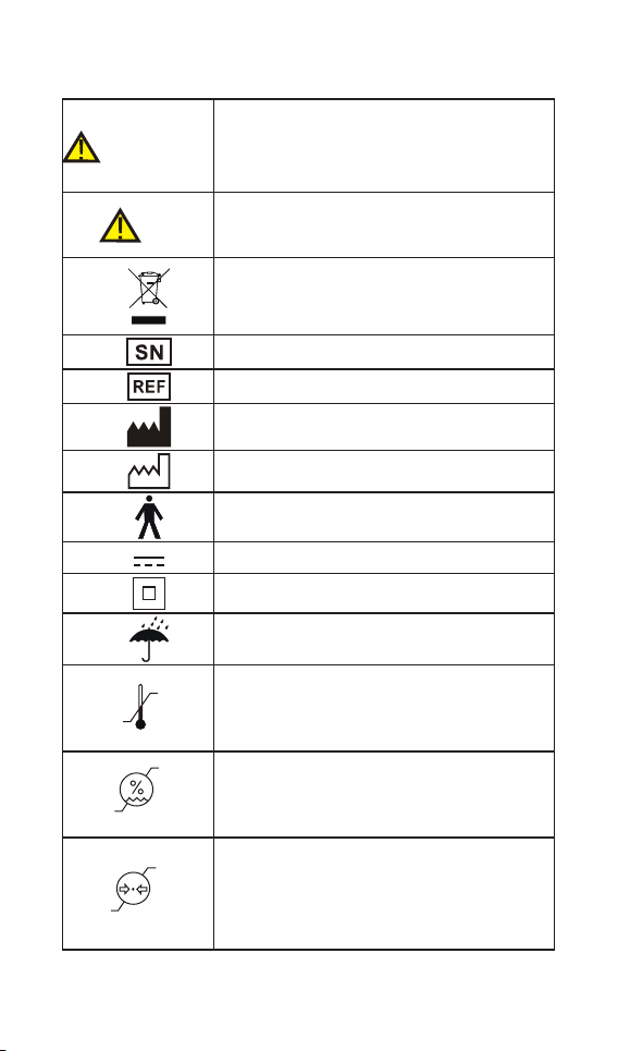
1. Symbols
If the instructions are not followed properly,
operation may lead to hazards for the
product or the user/patient.
NOTE
Additional information, explanation of
operation and performance.
Do not dispose of with normal household
waste.(WEEE)
Serial number
Catalogue number
Manufacturer
Date of manufacturer
Type B applied part
Direct current
Safety class II device
Store in a dry place
Temperature limitation
Relative humidity
Transport and storage pressure conditions: 70
kPa - 106 kPa
-20℃
55℃
80%
20%
106kPa
70kPa
Warning
3
Model
Dimensions(C25 Plus) 217mmX132mmX90mm
Weight 600g ±10%
Power supply Li-18650 battery: 3.7V, 2600mAh,
9.62Wh
Charger power supply AC 100-240 V, ±10%
Charger power output 5.0V 1A
Power Frequency 50/60Hz,±10%
Charger nominal power
input 5VA
Light intensity 2500mW/cm²
1200mW/cm²
Wavelength 420nm-515nm
Electrical safety class Class II
Applied part B
Operation conditions
Use: in enclosed spaces
Ambient temperature:
10° C ~ 40 ° C
Relative humidity: 20%~80%
Operating altitude < 3000m above sea
leve
Transport and storage
conditions
Ambient temperature: -20 ° C ~ +55
°C
Relative humidity: 20% ~ 80 %
Atmospheric pressure: 70kPa ~ 106kPa
2. Technical Data

4
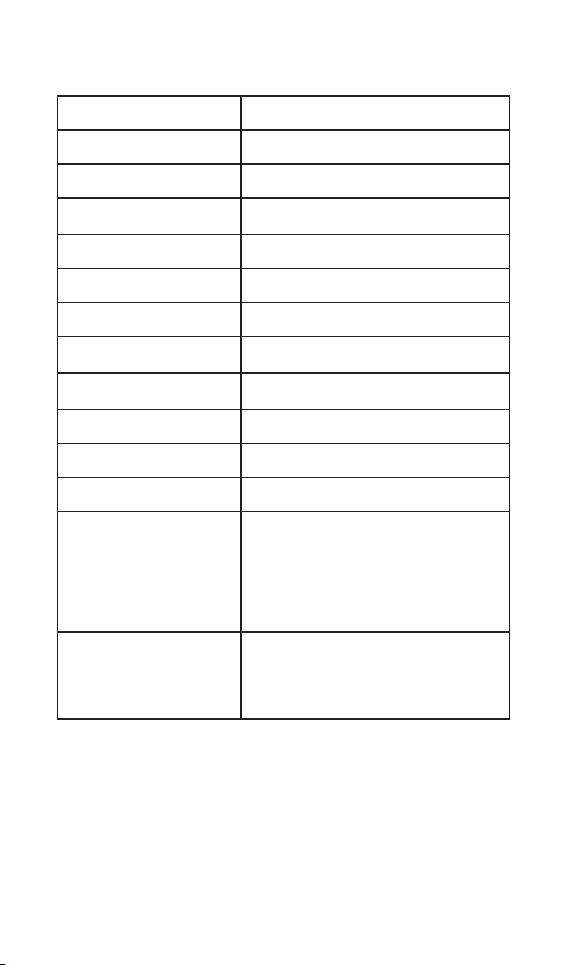
Light source head
Protective light shield
handpiece
Adapter
Disposable sleeve
Charging base
3. Scope
3.1 Parts Identification
4
1
2
3
5
6

5
3.2 Components and accessories
Handpiece (1pcs) Light source head(1pcs)
Disposable sleeve(100pcs) Adapter (1pcs)
Charging base (1pcs) Protective light shield (1pcs)
Warning
Read the following warnings before use:
1. The device must not be placed in humid surroundings or
anywhere where it can come into contact with any type of liquids.
2. Do not expose the device to direct or indirect heat sources. The
device must be operated and stored in a safe environment.
3. The device requires special precautions with regard to
electromagnetic compatibility (EMC) and must be installed
and operated in strict compliance with the EMC information.
In particular, do not use the device in the vicinity of fluorescent
lamps, radio transmitters, remote controls, portable or mobile RF
communication devices and do not use this system near the active
HF Surgical Equipment in the hospital .Do not charge, operate or
store at high temperatures. Comply with the specified operating
and storage conditions.
4. Protective light shield and a disposable sleeve are compulsory
during treatment.
5. If irregularities occur in the device during treatment, switch it off.
Contact the agency.
6. Never open or repair the device yourself, otherwise, void the
warranty
4. Before Use
4.1 Scope of application
Suitable for the purpose of curing dental resins and composites
or detecting caries.
This device must only be used in hospital environments, clinics or
dental offices by qualified dental personnel.
4.2 Contraindications
Do not use the device for non-endodontic dental procedures.
Safety and effectiveness have not been established in pregnant
women and children.

6
5.1 Install the light source head
Make sure the light source head
alignment the slots of handpiece,
plug them together until it
“click” securely into place.
The light source head can be 360
degrees rotated without take off,
make it easy to watch the LED in
treatment
5.3 Install the protective light
shield
Make sure the light source
head alignment the slots of the
protective light shield, plug them
together.
5. Setting up
Warning
1.After connecting the light
source head and the handpiece,
pull it gently to make sure the
connection is good.
2.Make sure the assembly is
connected properly, otherwise
might cause unexpected fault,
even hurt the patients
Warning
1.Disposable sleeve must be
discarded after use
2.The light source head, protec-
tive light shield and handpiece
should be cleaned and disin-
fected after each treatment.
Avoid direct exposure of
the lamp to the eyes during
working.
The lamp head can be adjusted
in angle to deal with different
positions
5.2Install the disposable
sleeve
Take a disposable sleeve
and gently insert it into the
handpiece from the light source
head.

7
5.4 Charging
Put the handpiece all the way into the charge base, the charge
state will show on the screen and plug the USB of adapter into the
charge base, and plug the other end into a power outlet, the Power
LED on charge base will light up (green).
Charging indication shows “CH” on the LED screen, and LED
flashes slowly , when battery is fully charged or in a state near full
charge, the flash will stop and show “FH”
Charging: Fully charged:
Warning
Only the original adapter could be used.
2
25
12
T
S
CH
2
T
S
FH
8
main switch
“T” Timing key
“S” Selecting key
Turn Power On
Press more than 0.5 seconds
to turn on the device
Time Change
Press Timing key during
standby state
Mode Change
Press Selecting key during
standby state
Power Change
Long press Selecting key
during standby state
Turn Power Off
Press Selecting key and
main switch to turn power
off.
Curing time
Curing power
Working mode
6. Use Interface
6.1 Panel key
1
2
3
2
T
S
0
E
1
2
3

9
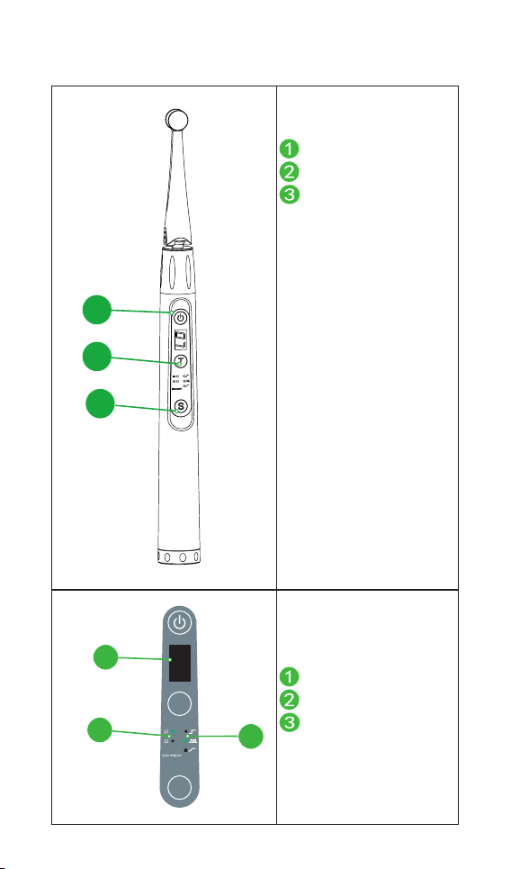
7. Setting
Curing Mode There are 3 built-in memory programs, namely
NORMAL, RAMP, PULSE. Press selecting key to
change the working mode during standby state.
Curing Power
Light intensity setting
The RAMP and PULSE mode are setting on
1200mW/cm², and NORMAL mode cand be
changed to 1200mW/cm² or 2500 mW/cm²,
Long Press “S” to change the light intensity.
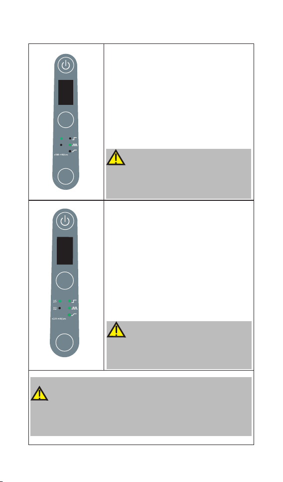
Curing Time
Curing Time setting
During standby state, press “T” to select dif-
ferent times. The time selection is different un-
der different light intensity:
Mode 2500mW/cm² 1200mW/cm²
NORMAL 1s,2s,3s 3s,5s,10s,15s
PULSE N/A 3s,5s,10s
RAMP N/A 5s,10s,15s,20s
7.1 Modify setting
Warning
The light intensity of RAMP, PULSE are built-in,
and the user cannot modify.
10
8. Operation
It means the battery is too low, less than
15% remains, please charge.
Charging indicator appears on the screen,
and flashes slowly , when battery is fully
charged or in a state near full charge, the
flash will stop and show as picture.
Fully charged will take about 4 hours, de-
pending on residual battery power and bat-
tery state.
It can be recharged 300-500 times, depend-
ing on the operating conditions of the de-
vice.
8.1 Charge
NOTE
If the power if less than 15%, must be
recharged within 30 days, otherwise the
battery will be damaged.
NOTE
When changing, other function will forcibly
stop, take from charge base, press main
switch, the last function will recall.
Warning
Do not change the battery, only trained technician or distributor
can change the battery, the electronic parts will be damaged if
use a wrong battery or install with a wrong way.
2
25
12
T
S
LO
2
T
S
FH

11
8.2 Handpiece operation
After the handpiece main unit is turned
on, press to start the light intensity
output, and the time will start counting
down. Press any key to interrupt the
output during the light intensity output.
There is a beep every 5s while working,
and the output is automatically turned
off after the countdown ends.
Auto Shut Down
When the device is in standby mode,
it will automatically shut down after 8
minutes.
Warning
1. When the device is working, do not
directly illuminate the eyes, otherwise it
will cause injury.
2.Do not directly illuminate the skin,
otherwise high temperature burns may
occur.
NOTE
1. After the device is used continuously
for 10 times at 2500mW/cm2, it will
be prohibited to use the highest light
intensity output within 1 minute, Used
to prevent the lamp from overheating
2. When using, the light should be
directly irradiated onto the curing dental
resins and composites to avoid improper
exposure.
3. The disposable protective cover
and protective light shield are highly
recommended.

12
9. Operation mode
Normal
Normal mode
In this modes, the light intensity can be set to
2500mW/cm² or
1200mW/cm²
Wavelength:420nm-515nm
When pressed, the setting light intensity is
output immediately, and the sound is prompted
every 5 seconds.
PULSE
PULSE Mode
Light intensity : 1500mW/cm²
Wavelength: 420nm-515nm
When pressed,the output light intensity is
1200mW/cm² and flashes once every 1 second,
prompting the sound every 5 seconds.
RAMP
Ramp Mode
Light intensity : 1200mW/cm²。
Wavelength:420nm-515nm
When pressed, the light intensity gradually
increases to 1200mW/cm² in the first 5 seconds,
and then continues to output 1200mW/cm²,
prompting the sound every 5 seconds.
Warning
1. Before using, please try it outside the oral cavity to ensure that
there is no problem with the function of the device.
2. Do not disassemble the lamp during treatment .
NOTE
1. If there is any abnormal functioning, stop using the device and
report to company
2. Gloves are compulsory during treatment
3 .Always clean the handpiece and light source head after each
treatment.

13
10. Maintenance
Disinfection components
handpiece Light source head Adapter
Charging base Protective light shield
Wipe all the surfaces with a cloth lightly moistened with Ethanol
for Disinfection (Ethanol 70 to 80vol%) at least 2min, repeat for 5
times.
Disposable components
Disposable sleeve(100pcs)
Warning
1. Do not use anything except Ethanol for Disinfection (Ethanol 70
to 80 vol%).
2. Do not use too much ethanol as it’s going into machine and
damage the components inside.
Warning
1. Please discard it after use and do not use it again.
2. The product has been disinfected with ethylene oxide, so there
is no need to disinfect it before use.
11. Error Warning
The battery is too low. Charge
it immediately
The temperature of the light
source head is higher than
expectation, turn the power
off or waiting more than 1
minutes to let it cold down.
2
25
12
T
S
LO
2
T
S
||||

14
12. Troubleshooting
When trouble is found, check the following points before contact-
ing your distributor. If none of these are applicable or the trouble
is not remedied even after action has been taken, the product may
have failed. Contact your
distributor.
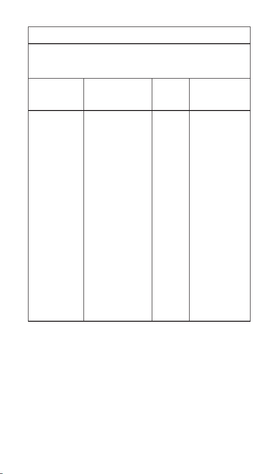
Problem Cause Solution Ref.
chap
The power is
not turned on.
The battery is run
down. Charge the battery. 8.1
The time to press
the main switch is
too short.
Press the main switch
more than 0.5 sec-
onds.
6.1
The Power LED
does not light
up when charg-
ing.
Use a wrong
adapter. Use the original adapter. /
There is no
electricity in the
outlet.
Check the connection. /
The adapter is not
connected.
Check the con-
nection. /
The charge base
broken. contact your distributor. /
Charging pin of
charge base una-
ble to
rebound.
Remove debris which
between move part and
base of the charge pin.
/
No output Handpiece
broken
Contact your
distributor /
No sound Handpiece
broken
Contact your
distributor
Insufficient
light intensity
There are resin or
other
contaminants on
the surface of the
lamp lens
Cleaning the lamp head
residue

15
13. EMC Tables
Guidance and manufacturer’s declaration – electromagnetic emissions
The C25 Plus is intended for use in the electromagnetic environment speci-
fied below. The customer or the user of the C25 Plus should assure that it is
used in such an environment.
Emissions test Compliance Electromagnetic environ-
ment-guidance
RF emissions CISPR 11 Group 1
The C25 Plus uses RF energy
only for its internal function.
Therefore, its RF emissions are
very low and are not likely to
cause any interference in nearby
electronic equipment.
RF emissions CISPR 11 Class B The C25 Plus is suitable for use
in all establishments, including
domestic establishments and
those directly connected to the
public low-voltage power supply
network that supplies buildings
used for domestic purposes.
Harmonic emissions
IEC61000-3-2 Class A
Voltage fluctuations/
flicker emissions
IEC 61000-3-3
Complies
Guidance and manufacturer’s declaration – electromagnetic immunity
The C25 Plus is intended for use in the electromagnetic environment speci-
fied below. The customer or the user of the C25 Plus should assure that it is
used in such an environment.
Immunity test IEC 60601 test lev-
el Compliance level
Electromagnetic
environment –
guidance
Electrostatic
discharge
(ESD) IEC 61000-
4-2
+/- 8 kV contact
+/- 2 kV, +/- 4 kV,
+/- 8 kV, +/- 15 kV
air
+/- 8 kV contact
+/- 2 kV, +/- 4 kV,
+/- 8 kV, +/- 15 kV
air
Floors should be
wood, concrete
or ceramic tile. If
floors are covered
with synthetic
material, the
relative humidity
should be at least
30 %.

16
Electrical fast
Transients
/bursts
IEC 61000-4-4
±2kV
100kHz repetition
frequency
±2kV
100kHz repetition
frequency
Mains power
quality should be
that of a typical
commercial or
hospital environ-
ment.
Surge
IEC 61000-4-5
Line to line:
±0.5kV, ±1kV
Line to earth:
±0.5kV, ±1kV,
±2kV
Line to line:
±0.5kV, ±1kV
Line to earth:
±0.5kV, ±1kV,
±2kV
Mains power
quality should be
that of a typical
commercial or
hospital environ-
ment.
Voltage dips,
short
interruptions and
voltage variations
on power supply
lines
IEC 61000-4-11
0% UT; 0.5 cycle
at 0 ° , 45 ° , 90 ° ,
135° , 180° , 225° ,
270° , and 315°
0% UT; 1 cycle
and 70% UT;
25/30 cycles
sine phase at 0°
0% UT; 250/300
cycle
0% UT; 0.5 cycle
at 0 ° , 45 ° , 90 ° ,
135° , 180° , 225° ,
270° , and 315°
0% UT; 1 cycle
and 70% UT;
25/30 cycles
sine phase at 0°
0% UT; 250/300
cycle
Mains power
quality should be
that of a typical
commercial or
hospital envi-
ronment. If the
user of devices
require continued
operation during
power mains
interruptions, it
is recommended
that devices be
powered form an
uninterruptible
power supply or
a battery
Power frequency
magnetic field IEC
61000-4-8
30 A/m
50Hz or 60Hz
30 A/m
50Hz or 60Hz
Power frequency
magnetic field
should be at levels
characteristic of a
typical location
in a typical com-
mercial or hospital
environment.
Note: UT: rated voltage(s); E.g. 25/30 cycles means 25 cycles at 50Hz or 30
cycles at 60Hz.
17
Guidance and manufacturer’s declaration – electromagnetic immunity
The C25 Plus is intended for use in the electromagnetic
environment specified below. The customer or the user of the C25 Plus
should assure that it is used in such an
environment.
Immunity test IEC 60601 test level Compliance
level
Electro
magnetic
environment -
guidance
Conducted
dis-turbances in-
duced by RF fields
IEC 61000-4-6
Radiated RF EM
fields
IEC 61000-4-3
Proximity fields
from RF wireless
communication
equipment
IEC 61000-4-3
3 V
0.15 MHz – 80 MHz,
6 V in ISM bands be-
tween 0.15 MHz and
80 MHz, 80 % AM at 1
kHz
3 V/m, 80 MHz – 2,7
GHz, 80 % AM at 1 kHz
See the
RF
wireless
communication
equipment
table
in “
Recommended
minimum
separation
distances”
3 V
3V/m
Complies
Portable and
mobile RF
communications
equipment should
be usedno closer
to any part of the
C25 Plus, including
cables, than the
recommended
separation distance
calculated from the
equation applicable
to the frequency of
the transmitter.
Recommended
minimum separation
distances
See the RF wireless
communication
equipment table in
“Recommended
minimum separation
distances”
18
Recommended minimum separation distances
Nowadays, many RF wireless equipments have being used in various health-
care locations where medical equipment and/or systems are used. When
they are used in close proximity to medical equipment and/or systems, the
medical equipment and/or systems’ basic safety and essential performance
may be affected. The C25 Plus has been tested with the immunity test level
in the below table and meet the related requirements of IEC 60601-1-2:2014.
The customer and/or user should help keep a minimum distance between
RF wireless communications equipments and the C25 Plus as recommended
below.
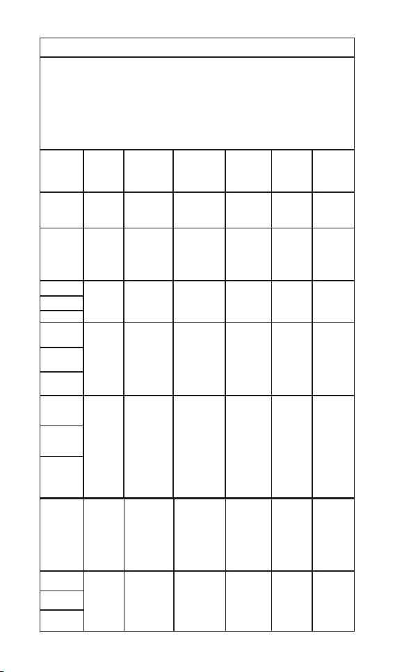
Test
frequency
(MHz)
Band
(MHz) Service Modulation
Maximum
power
(W)
Distance
(m)
Immunity
test level
(V/m)
385 380-390 TETRA 400
Pulse
modulation
18Hz
1.8 0.3 27
450 430-470 GMRS 460
FRS 460
FM
± 5 kHz
deviation
1 kHz sine
2 0.3 28
710
704-787 LTE Band
13, 17
Pulse
modulation
217Hz 0.2 0.3 9
745
780
810
800-960
GSM
800/900,
TETRA 800,
iDEN 820,
CDMA 850,
LTE Band 5
Pulse mod-
ulation
18Hz 2 0.3 28
870
930
1720
1700-
1990
GSM 1800;
CDMA
1900;
GSM 1900;
DECT;
LTE Band 1,
3,
4, 25;
UMTS
Pulse
modulation
217Hz 2 0.3 28
1845
1970
2450 2400-
2570
Bluetooth,
WLAN,
802.11 b/
g/n,
RFID 2450,
LTE Band 7
Pulse
modulation
217Hz 2 0.3 28
5240
5100-
5800
WLAN
802.11
a/n
Pulse
modulation
217Hz 0.2 0.3 9
5500
5785

19
14. Statement
Service Life
The service life of products is 5 years.
Disposal
The package should be recycled. Metal parts of the device are
disposed as scrap metal. Synthetic materials, electrical components,
and printed circuit boards are disposed as electrical scrap. The
lithium batteries are disposed as special refuse. Please deal with
them according to the local environmental protection laws and
regulation.
1. The main unit enjoys a 12-month warranty period,
which starts on our delivery date.
2. The host and other parts of the Curing Light are repaired by au-
thorized repair service partners.
3. If it is proved that the damage is caused by improper daily main-
tenance by the user, it is not covered by the warranty.
15. Warranty
Table of contents
Other Treedental Dental Equipment manuals


