Trejon OPTIMAL VPX Plough Guide

Instruction Manual and
Maintenance Directions
VPX Plough
From October 2018
Important!
Read the Instruction Manual
thoroughly before use
TREJON FÖRSÄLJNINGS AB
Företagsvägen 9
SE-911 35 VÄNNÄSBY
SWEDEN
Tel: + 46 (0)935 39 900
Web: trejon.se

Instruction manual TREJON OPTIMAL VPX plough (1810)
2

Instruction manual TREJON OPTIMAL VPX plough (1810)
3
CONTENTS
1Introduction........................................................................................................................... 7
1.1 General............................................................................................................................ 7
1.2 Description of VPX snow plough ...................................................................................... 7
1.3 Detailed description.......................................................................................................... 8
1.4 Technical specifications ................................................................................................... 9
1.5 Attachment with floating mode function.......................................................................... 10
1.6 Attachment..................................................................................................................... 11
1.7 Blank attachment ........................................................................................................... 11
1.8 Trejon Attachment –Table............................................................................................. 12
1.9 Support plates................................................................................................................ 13
1.10 Cutting edge................................................................................................................... 14
1.11 Cutting angle –adjustment............................................................................................. 15
1.12 Springs –pretensioning of cutting edges –adjustment................................................... 16
2Safety Instructions.............................................................................................................. 17
2.1 Safety Regulations......................................................................................................... 17
2.2 Safety symbols............................................................................................................... 20
3Using the machine .............................................................................................................. 21
3.1 Assembly ....................................................................................................................... 21
3.2 Coupling the plough to the machine............................................................................... 22
3.3 Hydraulics...................................................................................................................... 22
3.4 Hydraulic connection diagram........................................................................................ 23
3.4.1 4-hose ........................................................................................................................ 23
3.5 Plough steering –installation.......................................................................................... 24
3.6 Control box –function description .................................................................................. 25
3.7 Wiring diagram............................................................................................................... 26
3.8 Operating the Machine................................................................................................... 27
3.8.1 Please check the following before use:....................................................................... 27
3.8.2 Operating instructions................................................................................................. 28
3.9 Road transport ............................................................................................................... 28
3.10 Disconnection of the plough........................................................................................... 29
4Service and Maintenance.................................................................................................... 30
4.1 General.......................................................................................................................... 30
4.2 Maintenance schedule ................................................................................................... 31
4.3 Before season start........................................................................................................ 31
4.4 At End of Season........................................................................................................... 31
4.5 Lubrication points –location........................................................................................... 32
5Accessories......................................................................................................................... 33
7Spare Parts.......................................................................................................................... 34
7.1 Use original spare parts ................................................................................................. 34
8Notes.................................................................................................................................... 35
EC Declaration............................................................................................................................ 36

Instruction manual TREJON OPTIMAL VPX plough (1810)
4
SAFETY SYMBOLS
NOTE! You will find this general warning symbol throughout this Instruction Manual to make you
aware of safety instructions concerning yourself, your employees and other persons coming into
contact with the equipment. Neglecting these instructions may lead to serious injury and even
death.
This symbol has the following meaning:
WARNING!
LOOK OUT!
YOU ARE IN DANGER!
Warning Labels
Be aware of the warning words WARNING! and NOTE! in safety texts. These words have been
chosen based on the following guidelines:
WARNING! Warns of dangerous situations which, unless avoided, could lead to serious injury or
even death. This also includes dangers that can occur when protective equipment and/or
protective screens are removed. Warning labels can also be used to warn of hazardous use.
NOTE! Highlight risky situations where slight or minor injuries can result if they are not avoided.
Used also to warn of machine damage that can arise if the directions are not followed.

Instruction manual TREJON OPTIMAL VPX plough (1810)
5
Dear Customer!
Thank you for choosing a TREJON OPTIMAL product –we hope you will be pleased.
Reading this manual and following its recommendations will ensure you get the longest possible
service life and efficient use of the VPX plough.
We have produced this manual to give you a good overview of how the plough works as well as
the safety and maintenance directions that must be followed when working with it.
If any questions should arise when using the plough or reading this manual, you are always
welcome to contact us.
TREJON AB
Företagsvägen 9
SE-911 35 Vännäsby
Sweden
Tel: + 46 (0)935 399 00
E-mail: info@trejon.se
Website: www.trejon.se
Instruction manual TREJON OPTIMAL VPX plough (1810)
6
Dear Dealer,
In order for the warranty to come into force and for all legal requirements to be met, we would like
you to complete the warranty certificate together with the customer and to register at
www.trejon.se
The warranty will come into force on the same day as the plough is transferred to the customer.
Delivery inspection checklist:
Check for any transport damage. Report to carriers
Inspect the tool thoroughly before use and make sure all packaging has been
removed. Dispose of all packing materials in an environmentally responsible manner.
Check that the delivery is complete in accordance with the machine order/packing
note.
Make sure the machine has been lubricated as described under “Service and
Maintenance”.
Check tightness of all screw unions, see table for tightening torques in Service and
maintenance (Section 4).
Perform function test
With the assistance of the Instruction Manual, run through and explain
commissioning, use and maintenance of the plough and accessories to the
customer.
Complete the proof of transfer together with the customer and register at trejon.se
Instruction Manual handed over to customer.
Enter the serial number of the plough in the field
on the right
S/N:
Read through the entire Instruction Manual and
understand its contents before using the VPX folding
snow plough.

Instruction manual TREJON OPTIMAL VPX plough (1810)
7
1 Introduction
1.1 General
Before starting to use the plough, you are strongly recommended to carefully read through the
manual and safety instructions.
The user must be familiar with the VPX folding snow plough in order to guarantee safe usage.
1.2 Description of VPX snow plough
The VPX folding snow plough’s wings can be adjusted ±38°. This means that the plough can be
used both as a diagonal blade and as a folding snow plough.
The plough is intended to be connected to an existing attachment for agricultural tractors, loaders
and compact tractors. The TREJON OPTIMAL VPX folding snow plough can be equipped with
quick-coupling attachments for most tractors. The plough is equipped with a diagonal valve as
standard. This makes it possible to operate each wing independently or both wings together
diagonally.
The folding plough can be set in 3 different positions, depending on the type of work to be
performed. Y-CONFIGURATION for pavements, S-POINTED CONFIGURATION for conventional
road ploughing, street junctions and other areas where you can collect up and remove the snow,
D-DIAGONAL CONFIGURATION for clearing snow from car parks, streets, etc.
The VPX cutting blade works as standard with a 15° positive cutting angle. This provides an
efficient and clean cut, even at high speeds.
Y
S
D
Instruction manual TREJON OPTIMAL VPX plough (1810)
8
1.3 Detailed description
1. Left wing
11. Centre steel holder
2. Right wing
12. Steel holder
3. Rubber membrane
13. Centre frame
4. Support plate
14. Pin (centre frame)
5. Crank (support plate)
15. Hydraulic valve (diagonal valve)
6. Cylinder
16. Protective cover (Hydraulic valve)
7. Attachment / floating mode
17. 7-pole connector for spiral cable
8. Pin
18. Pressure accumulator
9. Cutting edge
19. Spring
10. Centre steel
9
10
1
2
3
5
4
6
7
8
11
12
14
13
15
17
18
16
19

Instruction manual TREJON OPTIMAL VPX plough (1810)
9
1.4 Technical specifications
All measurements in the table are for VPX ploughs equipped with a standard (smooth) cutting edge.
Model
Dimensions
VPX290
VPX330
VPX370
Total width [mm]
B
2990
3280
3700
Width, D-configuration [mm]
D
2410
2740
3120
Height [mm]
H
950
1050
1130
Width, S-configuration [mm]
S
2470
2700
3050
Length, S-configuration [mm]
K
1015
1110
1280
Width, Y-configuration [mm]
Y
2350
2580
2880
Length, Y-configuration [mm]
L
1885
2040
2230
Blade angle [°]
±38°
±38°
±38°
Weight [kg]
615
755
905
Operation
Hydr./Elec.
Hydr./Elec.
Hydr./Elec.
El. voltage* [V]
12
24
24
Hydraulic connection
G½” Faster
male (x2)
G¾” TEMA
female (x2)
G¾” TEMA
female (x2)
* As standard, the plough is supplied for the voltage indicated in the table. If a different voltage is required, contact
Trejon or read section 5 –Accessories.
Instruction manual TREJON OPTIMAL VPX plough (1810)
10
1.5 Attachment with floating mode function
The floating mode attachment is movable for vertical pivoting and twisting (horizontal) (see figures
1, 2 and 3 below for a description of the movement capacity).
It is important to position the floating mode attachment so that it can move freely up and down.
Lower the plough to the ground. Lower the attachment to its end position (see Figure 2) and then
lift the attachment approximately 70-80 mm. In this position (floating mode), the plough is able to
follow the surface optimally.
Figure 1 –Vertical movement, up Figure 2 –Vertical movement, down
Figure 3 –Rotation
Figure 4 –Hole pattern

Instruction manual TREJON OPTIMAL VPX plough (1810)
11
1.6 Attachment
The type of attachment / hook (1) for the machinery’s loader (3) or suspension must always be
specified when ordering a VPX folding snow plough. It is important to use the correct tightening
torque: M20 (420 Nm) and M16 (215 Nm) for all bolts (4) when installing the attachment / hook (1)
on the plough’s floating bracket (2).
Figure 5
Warning!
Loose or poorly tightened bolts can cause the plough to come loose and cause
material damage and/or personal injury!
1.7 Blank attachment
There are many different machines. In those cases where the Trejon does NOT have a ready-
made attachment, customers can weld these onto a blank plate themselves. There is a ready-
made kit for this, art. no. 84005 –see Figure 6. Customers can weld attachment hooks for the
load carrier themselves. For mounting on a VPX plough, read section 1.6.
Warning!
It is the person who welds/manufactures the attachment who is responsible for
any incorrectly performed welding/manufacturing that may result in future injuries
or accidents.
Figure 6
2
3
4
1
A
VPX

Instruction manual TREJON OPTIMAL VPX plough (1810)
12
1.8 Trejon Attachment –Table
The VPX plough can be equipped with various attachments. The following table lists Trejon’s art.
nos. for the most viable alternatives. All these are suitable for the VPX plough’s floating mode
attachment.
Model
Kit art. no.
C-C [mm]
(internal)
Location of stop
lug (ST)
Other
Volvo BM
12433
960
Outside
Fits Terex TL160
Kunta 500
60121
960
Outside
-
3-point Cat. 2
15405
800
-
Wider (W) side facing inwards
Trima
12432
650
-
Wider (W) side facing inwards
Euro
13266
995
Outside
-
Zettel 502
60122
860
Inside
Fits JCB 409B
Zettel 402
60131
650
Inside
Fits Volvo L25B
It is important to maintain the C-C dimensions (see Fig. 7) when installing the attachments. The
location of the stop lug (ST) is also an important part of the installation.
Figure 7
ST
W

Instruction manual TREJON OPTIMAL VPX plough (1810)
13
1.9 Support plates
The VPX folding snow plough is equipped with two support plates, which can be adjusted using a
crank (size NV19) to the desired position. Remove the ring pin (1) and lock plate (2) from the
adjustment screw (3) before carrying out height adjustment –see Figure 8. Use the crank (4) for
height adjustment 360° = 5 mm –see Figure 9. Restore the lock plate (2) and cotter pin (1) to lock
the adjustment screw (3) following height adjustment –see Figure 10.
Figure 8 Figure 9 Figure 10
When ploughing for the first time or when the roadway is soft, it can be an advantage to raise the
folding snow plough (X ≥ 0) (see Figure 11). This is done to prevent unnecessary wear on the
cutting blade and to avoid cutting up gravel.
After ploughing a few times or once the roadway has frozen and become hard, you are
recommended lower the folding plough by adjusting the support plates upwards to the same level
(X = 0) as the cutting edge (see Figure 12).
Better ploughing results are achieved once this has been done.
NOTE!
Always replace damaged or worn support plates in time –Trejon art. no. 980002. If
the plate comes loose, the support leg will also be damaged. This is NOT covered
by any warranty.
NOTE!
Make sure that the support plates are the same height on both sides.
Damage due to incorrect adjustment is NOT covered by any warranty.
Figure
11
Figure
12
1
2
3
3
1
2
4

Instruction manual TREJON OPTIMAL VPX plough (1810)
14
1.10 Cutting edge
The VPX plough is equipped with the following cutting edges (A, B, C –see Figure 13.). The
cutting edges are sprung (F) and reversible. The outer cutting edges (a) have a bent edge which
reduces the risk of becoming stuck in obstacles.
The sprung cutting edges reduce damage in the event of a collision. Standard cutting edges can
be reversed by switching from left to right.
It is important to check wear and tear on the cutting edges daily. There are many factors that affect
this. These factors include ploughing speed, substrate, cutting angle, support plates and
adjustment of the floating mode. It is therefore important to maintain the distance W ≥ 10 mm
between the lower edge of the cutting edges (1) and the lower edge of the steel holder (2) (see
Figure 14).
When the wear is significant and the distance W≤ 10 mm (see Figure 15), it is time to move all the
cutting edges downwards (see Figure 16). When this position is also worn, the cutting edges (B)
are turned or shifted (from left to right and vice versa); this applies to the cutting edges with bent
ends (A).
It is important that the cutting edges do not protrude downwards more than 60 mm, i.e. W max. =
60 mm.
Figure 13
B
A
C
C
B
A
F
Figure 16
Figure 14
2
1
Figure 15
A
B
Instruction manual TREJON OPTIMAL VPX plough (1810)
15
C
Two extra centre cutting edges (C) are supplied with each VPX folding snow plough. They are
located on the right-hand side of the centre frame –(see Figure 17)
You are recommended to order new centre cutting edges, art. no. 85708, as soon as the last pair
has been installed on the plough.
NOTE!
Trejon Optimal cutting edges are made of the highest quality steel to provide a
low overall cost. The cutting edges are wear components and their service life
CANNOT be determined. The cutting edges are NOT covered by any warranty.
NOTE!
Damage due to the use of other cutting edges is NOT covered by any warranty.
NOTE!
Replace the cutting edges when they have become worn.
1.11 Cutting angle –adjustment
The default cutting angle is 15° (Z = 420 mm) –see Figure 18. In general, cutting angles only need to
be adjusted after the springs have been replaced –see section 1.12.
Dimension Z –see Figure 18 –can be used as a control measure. By tightening the nut (M) in the
upper part of the spring rod (P), the cutting angle is smaller –for cutting angle 0°, Z = 390 mm.
Loosening the nut (M) makes the angle larger.
Figure 17
M
P
Figure
18

Instruction manual TREJON OPTIMAL VPX plough (1810)
16
1.12 Springs –pretensioning of cutting edges –adjustment
NOTE!
If the pretension of the cutting edges is too high, there is a risk of accidents and of
the device breaking. Sprung cutting edges are a safety arrangement, and they are
intended to make ploughing safe. If any of the springs has become deformed or broken off,
we recommend that all the springs on the blade be replaced, art. no. 200595.
The default pretension, i.e. spring Y dimension, is 330 mm –see Figure 19.
To increase the pretension, adjust Y dimension as follows:
1) Loosen nuts M1 and M2 in the lower part of the spring –see Figure 19
2) Tighten nut M1 upwards two turns at a time and test operate. Repeat until the tension is
just right –see Figure 20
3) Tighten nut M2 against nut M1 to lock the spring –see Figure 21
NOTE!
If the pretension of the cutting edge is too low, the cutting edge constantly gives
way, the ploughing results are poor, the plough jumps and causes unnecessary
noise.
To decrease the pretension, adjust Y dimension as follows:
4) Loosen nuts M1 and M2 in the lower part of the spring –see Figure 21
5) Tighten nut M2 downwards –see Figure 20
6) Tighten nut M1 downwards two turns at a time and test operate. Repeat until the tension is
just right –see Figure 20
7) Tighten the lower nut M2 against nut M1 to lock the spring –see Figure 19
Figure 19
Figure 20
Figure 21
M1
M2
M1
M2

Instruction manual TREJON OPTIMAL VPX plough (1810)
17
2 Safety Instructions
2.1 Safety Regulations
Read the manual. All machine operators should read and understand the entire contents of this
manual and the safety regulations so there is no uncertainty as to the use of the machine/tool
before it is taken into service. Get in touch with your dealer if you have any questions.
Use of the machine is strictly forbidden if the operator is not aware of the risks involved in
conjunction with the use of the machine and cannot act correctly if a risk situation should arise.
Read, observe and understand the meaning of all safety, operating, warning and positioning
decals on the machine and in the manual.
Actions may occur when using this equipment that cannot be prevented in its design or with the
use of mechanical protection.
Unfortunately, human carelessness may cancel the function of our integrated safety features.
Accordingly, the prevention of accidents and operating safety features are dependent on the
responsible use of the equipment and its integrated safety features.
Only trained personnel should use this equipment.
The machine is intended for snow clearing only.
Operation. Learn and practise the machine’s working methods and controls before it is used.
Coupling the Machine. Connect the machine in the correct manner and keep away from the area
between the tractor and the machine when coupling.
Make sure the equipment is correctly mounted, adjusted and in working order.
Safe Work Area. Keep unauthorized persons, especially children, away from the working zone of
the machine or when it is being repaired.
Be aware of the risk of injury from material that may be ejected by the machine while work is in
progress.
Ensure all warning and operating decals are in good condition and affixed in the correct manner,
and replace them if necessary. Write the model and serial number when ordering.
Moving Parts. Keep arms, legs and other body parts as well as clothing away from any moving
parts of the machine.
Lifting and lowering of the machine.
Be careful when lifting and lowering the machine/machine part.

Instruction manual TREJON OPTIMAL VPX plough (1810)
18
Stability. The machine must not be operated with a tractor that does not weigh enough over the
front/rear axle, such that the steering and stability of the tractor are affected. Mount ballast weights
if necessary, see tractor instruction manual.
Operating the Machine. Take great care when working on uneven ground conditions, close to
ditches and fences, look out for hidden dangers and adapt your working rate.
Do not reverse with the plough down (the wrong way)
Great care should be observed when working on steep slopes:
Try to drive in the same direction as the incline and not across it.
Avoid fast starts and heavy braking when driving the machine up and down inclines.
If it is absolutely necessary to drive across steep inclines then reduce your speed and watch out
for unevenness, avoid sudden turns and be aware of the shift in centre of gravity that occurs when
lifting mounted tools.
Hold onto the steering wheel tightly if the tractor should overturn.
Operating at Night. The work area must be illuminated when working in the dark.
Driver. Operators who are tired, intoxicated, drugged or under the influence in any other way so
that they cannot control their movements must not use the machine.
The machine may only be operated by one person sitting in the tractor, no passengers are
allowed.
It is prohibited for people without authorisation to use the machine.
Personal protective equipment. Protective equipment such as helmets, protective goggles,
protective shoes and gloves are recommended for personnel during assembly, operation,
adjustment and maintenance.
Protective Cab. The machine should only be driven by a tractor equipped with an approved
protective cab. Keep doors and windows close while working.
All moving parts, including engine, must be stationary and the handbrake applied before the tractor
driver leaves the cab. When travelling on ice-covered water the roof hatch must be kept open.
When travelling on ice-covered water the roof hatch must be kept open.
Maintenance. Inspect, adjust and maintain the machine according to the directions.
Regular Inspection. Inspect the entire machine regularly. Locate any loose, worn and damaged
components and leaks.
Safety During Maintenance and Service. The machine must be standing on firm, even ground
for maintenance and adjustment.
The tractor engine must be shut off, all moving parts stationary, the machine lowered to the ground
and the handbrake applied during all cleaning, inspection, adjustment, maintenance and repair
work.
Clean the machine thoroughly before repair and storage.
Bearing and hydraulic components should not the cleaned with high-pressure jets.
If excessively high pressure is used for general cleaning, this may damage the paint.
After cleaning, the machine must be lubricated according to the lubrication schedule and a short
test run carried out.
Vibration. If any vibration should occur in the machine, it must be shut down immediately and the
cause located. Change any damaged parts.
Emergency stop. Stop the machine immediately if it should hit an obstruction. Shut off the engine,
remove the key, check for and repair any damage before recommencing work.
Make yourself aware of how emergency stops work on the tractor and the tool, and be prepared of
how they work in an emergency situation.

Instruction manual TREJON OPTIMAL VPX plough (1810)
19
Hydraulic hoses. Hydraulic hoses on the machine contain oil at very high pressure. Do not touch
hoses and hydraulic components if the system is pressurised. In case of leaks, oil at high pressure
may penetrate the skin and cause serious injury. In the event of an accident, contact a doctor
immediately.
Check the condition of hydraulic hoses daily with respect to damage. Chafed and leaking hoses
should be replaced immediately with new that meet the manufacturer’s technical requirements.
When changing tractor, always check the length of hoses. Hoses that are too long or too short may
be damaged.
The use of incorrect hydraulic hoses that do not meet with specifications is strictly forbidden.
Hoses can become hot while in operation, with the risk of burn injuries. Do not loosen hoses
while the oil is hot, wait for it to cool down.
Welding. Protect bearings, hydraulics and electronic components if welding is being carried out.
Before welding commences, electronic components must be disconnected and the welder’s
ground clamp placed as close to the welding site as possible.
Electrical Lines. Take great care when working close to electrical lines, maintain a safe distance
with good margin.
If an accident should occur such that the plough comes into contact with live lines:
-Keep calm, act rationally so as not to worsen the situation and do not touch any metal
parts.
-Warn people in the vicinity and make sure they stay outside the risk zone.
Spare Parts. Use only original spare parts on the machine.
If you should have any questions concerning the machine or its function, please get in touch with
your dealer or Trejon AB
Instruction manual TREJON OPTIMAL VPX plough (1810)
20
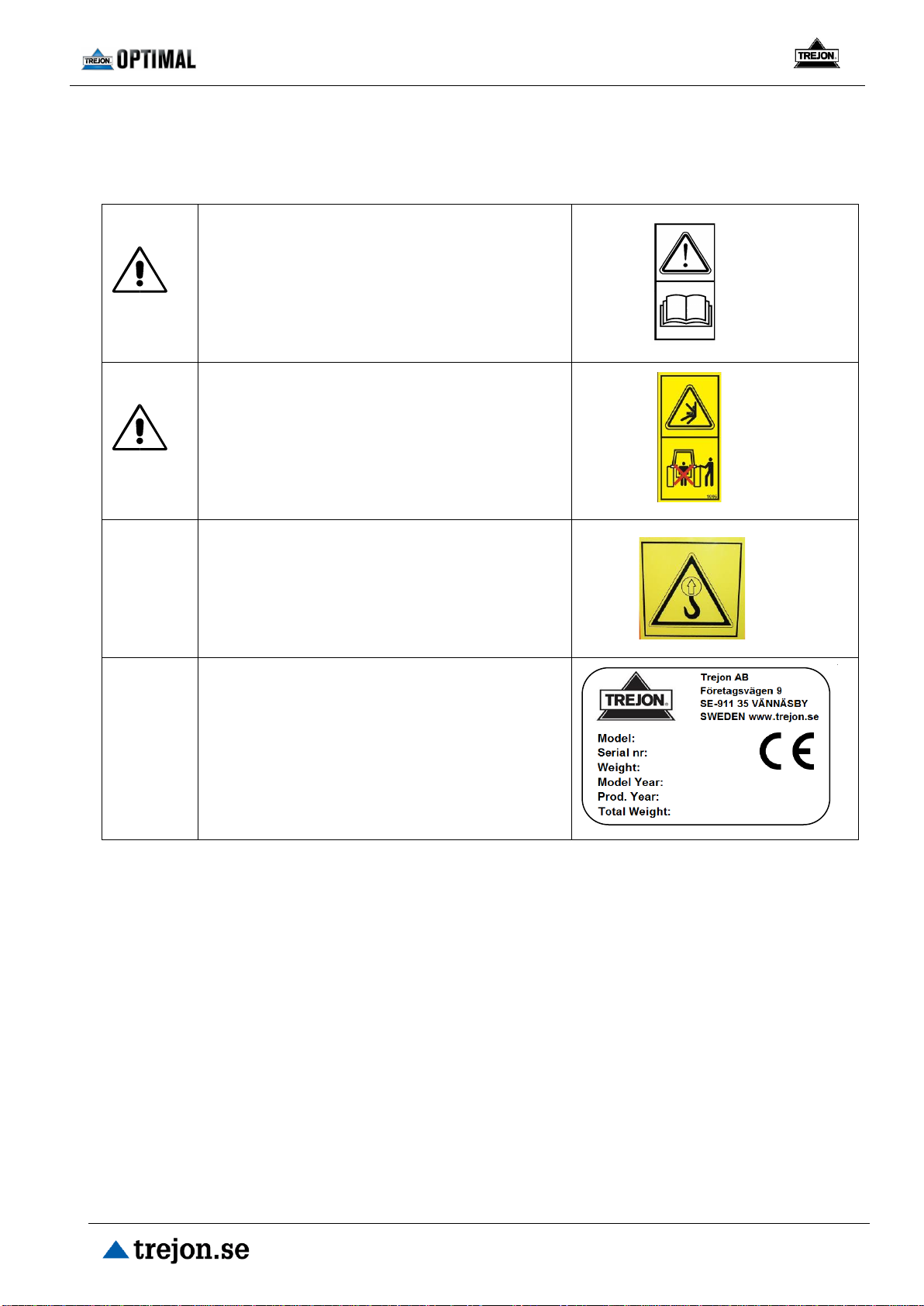
2.2 Safety symbols
The symbol on the right shows the following:
Warning!
Study the instruction manual carefully before
use, so that the user knows the machine well.
Warning!
Crush risk! Do not stand between machine,
machine parts and tractor when coupling.
Always brake the tractor, turn off the engine
and remove the ignition key when leaving the
cab during coupling or decoupling operations.
Indicated lifting point.
Machine name plate with CE marking. This
includes the model designation, the machine’s
serial number, weight and year of manufacture.
This manual suits for next models
1
Table of contents


