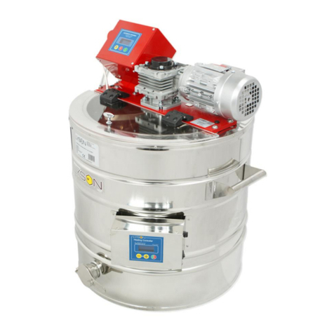
LYSON C-01 User manual

MANUAL FOR A CREAMING MACHINE ON A
DECRYSTALLIZER WITH AUTOMATIC CONTROLLER
C-01
POWER SUPPLY 400V
(50l-200l, 600L)
Przedsiębiorstwo Pszczelarskie Tomasz Łysoń
Spółka z o.o. Spółka Komandytowa
34-125 Sułkowice, ul. Racławicka 162, Polska
www.lyson.com.pl, email; [email protected]om.pl
tel. 33/875-99-40, 33/870-64-02
Siedziba Firmy Klecza Dolna 148, 34-124 Klecza Górna

The following manual encompasses the
devices bearing the following codes:
POWER SUPPLY 400V:
W20087, W20087C, W20085, W20086, W20089,
W200890
1. General safety principles for using the
creaming machine
1.1. Electric safety
1.2. Usage safety
2. Characteristics for a creaming machine
with a heating mantle
2.1Honey creaming
2.2 Diagram for the creaming machine with
heating mantle
2.3 Technical parameters for the creaming
machines
3. C-01 controller for the creaming machine –
power supply 400V
3.1 Button description – controller functions
3.2 Setting up the “stirring cycle”
4. Temperature regulator
4.1 Setting up the controller
4.2 Starting the controller’s operation
4.2 Error report for the controller
5. Storing the creaming machine with a heating
mantle
6. Cleaning and maintenance
7. Recycling
8. Guarantee

2. Characteristics of the creaming
machine with a heating mantle
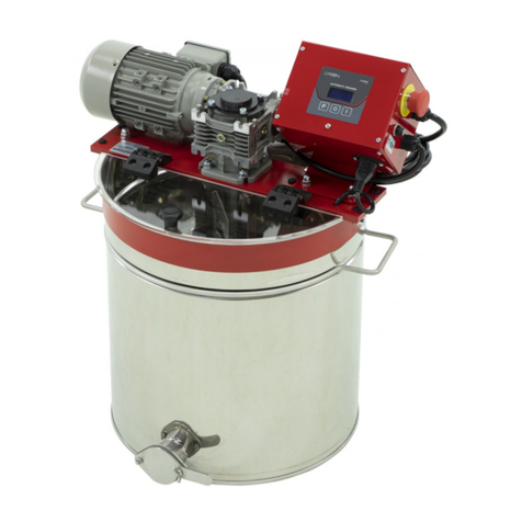
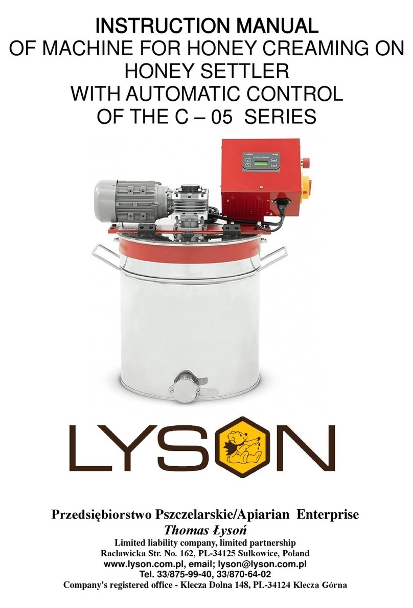
The honey creaming machine with a heating mantle is
intended to cream and melt the crystallised honey.
The proper design of a stirring propeller made of stainless
and acid resistant steel allows to cream the honey precisely.
2.1. Honey creaming
Fresh honey remains dense and transparent. With time it is
subject to natural crystallization. Proper temperature for
crystallization ranges between 16-18ºC. With higher
temperatures, the crystallization process slows down and
the crystals have bigger sizes
Heating honey until the temperature of 40ºC and its
maintenance by several days makes the honey switch from
crystallized state (set honey) to liquid state ( strained
honey).
Creaming remains a quick and simple method to produce
creamed honey. It consists in adding crystallized honey (set
honey) to freshly centrifuged and clear liquid honey
(strained honey) in order to initiate controlled, fine-grained
(creamed) crystallization. The creaming process should be
run in repetitive cycles:
Stirrer operation - 15 min; stirrer stoppage 1h.
The creaming machine possesses a special mechanical
stirrer which allows to perform the re-crystallisation process,
after which honey achieves a consistency similar to
chocolate creams.
The process is based on cyclical aeration and intensive
honey stirring for several days until the proper consistency
has been achieved. Honey stored in constant temperature
shall maintain the consistency for many months.
Mixing is to be performed several time in a day for
approximately 10-15 minutes.
For example, one may start by adding crystallised honey to
the liquid one.
"Creaming" is intended to formulate numerous small
crystallization nucleuses and to block the expansion of the
already existing honey crystals. It is referred to as
“mechanical honey crystal creaming”.
The process shall be run gradually, i.e. small quantities
of honey must be added gradually instead of filling the
entire device with it .
2.2.Diagram for a honey creaming machine
with a heating mantle
Legend:
1. Internal mantle
2. External mantle
3. Insulation
4. Stirrer
5. Engine
6. Cover
7. Stainless steel valve
8. Grips
9. Heating cable
10. Controlling
11. Transmission
2.3. Device technical parameters
a. tank made of stainless and acid resistant steel plate
b. transmission engine power supply 400 V
c. digital display in the temperature regulator.
d. rotational speed for the stirrer – 36 rpm
e. stainless steel valve 5/4”, 6/4” ,2”
3. C-01 CONTROLLER FOR THE CREAMIGN
MACHINE – POWER SYPPLY 400V
Automatic controller controls the operation of the stirrer.
Controller operation boils down to cyclical activation and
deactivation of the creaming machine stirrer engine .
The number of cycles for engine activation depends on the
total operating time, however it is calculated in the following
manner, each 15 minutes of the stirrer operation
corresponds to 1 hours of stoppage (optimal parameters for
the creaming process).
Temperature regulator

For example, the cycle with the total duration of 24
hours means 20 cycles of engine activation for 15 minutes
each as well as 19 stoppage cycles of 1 hour each one
Fig 1. Creaming machine controller handling panel
3.1. Description of buttons – functions of the
controller
Once power supply is connected, the controller performs
self-diagnostics to acknowledge the correct device operation.
Error detection is signalled by the relevant code being
displayed on the LCD screen
If errors have not been detected, the screen display will look
like in Fig. 2.
Fig. 2. Depending on the previous set-ups, the screen
will display previously preset creaming machine
operating time.
The controller possesses several programmes , which
allows to select precisely the total creaming time ranging
from 24 hours to 99 hours as well as 1 hour in special cycle
(for the devices on a de-crystallizer).
Controller handling boils down to the selection of a
programme ( by pressing the “P” button and subsequent
activation of selected programme cycle by pressing the
START button.
In order to select a proper operating time for the creaming
machine, “P” button shall be pressed, as in Fig. 3 and the
device operating time shall be set: (24h, 36h, 48h, 60h,
72h, 84h, 96h, 99h).
Fig. 3 Selection of programme.
In order to activate the creaming machine stirrer operation,
press START button, as in Fig. 4
Rys. 4 Programme activation
The screen of the controller working with activated
creaming cycle specifies the time that has passed since the
cycle activation. (Fig. 5). Additional icon informs about the
stirrer activation mode.
(no icon – stirrer stoppage, visible icon – stirrer rotates)
Fig 5. Activated creaming cycle
STOP button allows to deactivate the programme
performed (Fig.6).
Re-activated programme will operate from the beginning ,
i.e. operating throughout the entire time specified.
Proper termination of the creaming cycle is signalled by an
inscription OK (Fig .7) showed in the display screen
Czas, jaki upłynął
od włączenia cyklu
P
START
STOP
2:30
Cycle execution time
Time that has passe since
the creaming machine activation
PSTART
STOP
24h00m
1 2 3

Fig. 6 Stopping the creaming process.
Fig. 7 Terminated creaming cycle
3. 2 SETTING UP THE “STIRRING CYCLE”
The “Stirring Cycle” allows to configure the controller from
constant stirrer operation for one hour.
Activation of the cycle is possible only in the creaming
machines equipped with heating system (i.e. on the de-
crystallizer) !!!
In order to activate the Stirring Cycle, during the controller
start-up (“ŁYSOŃ-C01 note shall appear), one should press
and hold STOP button and Pbutton at the same time.
Having entered the menu on the display screen, a message
informing on the active programming mode (“Prog”) is
displayed and when both buttons are released the current
configuration of the “Stirring Cycle” is showed
Changing the “Stirring Cycle” configuration is possible by
pressing the “P” button.
Configuration 1h=on (permanent stirring for 1 h) means
that 1h programme will be on. Respectively, configuration
1h=off (permanent stirring for 1 h) means 1 h function will
be off.
Leaving the “Cycle programming” is possible by pressing
STOP button.
P = 1h (permanent stirring cycle),
Fig. 8. „Stirring cycle” for the controller
Once the creaming machine cover has been opened,
security lock mounted on the creaming device cover shall
stop the creaming cycle (stoppage state, if such one was
active). STOP message will appear on the display screen
and time counting will stop. Cover reclosing means the
return to the state in which the controller was before the
safety cover had been opened, i.e. continuation of the cycle
stopped.
Fig. 9. Message regarding the creaming machine
stopping.
Error codes
FAILURE
CODE FAILURE DESCRIPTION
E-001
INTERNAL FAULT OF THE
MICROPROCESSOR
CONTROLLER
E-002
PRESSED/BLOCKED “START”
BUTTON
E-003
PRESSED/BLOCKED “P”
BUTTON
E-004
PRESSED/BLOCKED “STOP”
BUTTON
PSTART
STOP
OK
PSTARTSTOP
STOP
Czas wykonania
cyklu
Exit

4. Temperature regulator MHC-01
The device has been equipped with MHC-01 temperature
regulator.
Heating Controller
c
456
3
12
4.1. Setting up the controller
1. Prior to plugging in the device to the mains, one
must make sure that the controller is switched off.
2. Switch (0/1) on the control panel shall be in “0”
position
3. Once plugged in to the mains, Switch (0/1) shall be
moved from “0” position to “1” position
4. Controller should be programmed in line with
individual needs
5. In order to enter the programming mode (Prog),
buttons “+” and “-“ must be pressed at the same time
during controller start-up.
4.2. Starting work with the controller
1 – signalling the work state
Indicator lights up – temperature regulator switched on,
indicator dimmed – temperature regulator switched off
(controller operates as an ordinary thermometer), indicator
flashes – temperature regulator switched on and initial
heating in progress
Indicator lights up – transmitter contacts closed (heating
on), indicator dimmed – contacts opened (heating off)
3 – display
Working mode – default mode, selected after controller
power supply switched on. The display shows the measured
temperature, readings specified in oC.
Setting mode – selected when button “+” or “-“ has been
pressed. The display shows the preset temperature.
Readings specified in oC. Reading flashes and returns to
measured temperature after a while.
Working time setting mode (Pro.) – activated when
“ON/OFF” button is pressed and held. The display shows
working time, counting it from activation, after which the
thermostat gets switched off. Readings specified in hours.
Display brightness setting mode (d.br.) – activated when
“ON/OFF” button is pressed and held for a longer time. The
display shows the currently set brightness on all its
segments . When the setting limit values are reached, the
segments start to flash.
The modes specified below are accessible once the
relevant code have been entered.
Calibration mode (CAL.) code L-1 – activated when the
“ON/OFF’ button has been pressed and held for a longer time.
The display shows the measured temperature including the
calibration. Readings specified in oC.
Preliminary heating time setting mode (P.tI.) code L-2 –
activated when “ON/OFF” button is pressed and held for a
longer time. The display shows the working time, counting it
from the activation, for which the controller performs
preliminary heating maintaining the preliminary heating
temperature programmed by the manufacturer. Reading
“OFF” means deactivation of the preliminary heating function.
Readings specified in minutes. When preliminary heating
activated, the controller displays marking “HC2” during start-
up.
Preliminary heating temperature setting mode (P.tE.)
code L-3 –activated when the “ON/OFF” button is pressed
and held for a longer time. The display shows the value of
preset temperature for preliminary heating. Readings P …
specified in oC.
Preset temperature limit setting mode (L.t.h.) code L-4 –
activated when “ON/OFF” button is pressed and held for a
loner time. The display shows maximum value of preset
temperature that can be set . Readings L … are specified in
4 – button „-„ value decreasing
Working mode – pressing the button will decrease the
preset temperature value. During preliminary heating, the
option to change the setting for preset temperature is blocked.
Working time setting mode – pressing the button will
decrease the time after which the thermostat will get
switched off.
Display brightness setting mode – pressing the button will
decrease the brightness of the display.
Calibration mode – pressing the button will decrease the
value of the temperature to be transferred, calibrating the
measurement duct in this way.
Preliminary heating time setting mode – pressing the
button will decrease the time after which the thermostat will
switch from preliminary heating phase to proper heating
phase.
Preliminary heating temperature setting mode – pressing
the button will decrease the value of preset temperature that
will be maintained during preliminary heating.
Preset temperature limit setting mode – pressing the
button will decrease the value of maximum preset
temperature that will be to set.

5 – button „+” value increasing
Working mode – pressing the button will increase the value
of preset temperature. During preliminary heating, the preset
temperature setting changes is blocked.
Working time setting mode – pressing the button will
increase the time after which the thermostat gets switched
off.
Display brightness setting mode – pressing the button will
increase the brightness of the display
Calibration mode – pressing the button will increase the
value of the transferred temperature, calibrating the
measuring duct in this way.
Preliminary heating time setting mode – pressing the
button will increase the time after which thermostat switches
from preliminary heating phase to proper heating phase.
Preliminary heating temperature setting mode pressing
the button will increase the value of preset temperature
which will be maintained during preliminary heating.
Preset temperature limit setting mode – pressing the
button will increase the value of maximum preset
temperature that can be set
6 –„ON/OFF” button
Short-time pressing of the button will activate (ON) and
deactivate (OFF) the regulator interchangeably. At
deactivated state (OFF) the regulator act as a thermometer.
At activated state (ON) , the regulator shall activate and
deactivate the outlet to control the heater in order to maintain
the temperature set by the user.
Longer pressing and holding of the button and subsequent
button releasing will activate the working time setting mode,
signalled with (Pro.) notice. In this mode, by means of “+” and
“-“ buttons , the user has a possibility to define the time after
which the controller gets deactivated, i.e. switches to the
OFF state. Exit from the mode and setting approval occurs
once the “ON/OFF” button is shortly pressed.
Longer pressing and holding of the button and its
subsequent releasing will activate the display brightness
setting mode – signalled with (d.br) notice.
In this mode, by means of “+” and “-“ buttons the user has
the possibility to set the brightness of the display segments.
Exit from the mode and confirming the setting occurs when
the “ON/OFF” button is pressed shortly. Longer pressing and
holding of the button and subsequent releasing of the button
will activate the calibration mode, signalled by the (CAL)
notice. In this mode by means of “+” and “-“ buttons, the user
has a possibility to adjust the temperature readings to the
real temperature. Exist from the mode and confirming the
calibration settings occurs when the “ON/OFF” button is
pressed shortly.
NOTE – the controllers supplied have been calibrated
already.
Longer pressing and holding of the button and subsequent
its releasing shall activate the preliminary heating time
setting mode, signalled by (P.tl) notice. In this mode by
means of “+” and “-“ buttons the user has a possibility to
define the time after which the controller gets switched from
preliminary heating phase to proper heating phase.
Deactivation of preliminary heating is signalled by the “OFF”
notice. Exist from the mode and setting confirmation occurs
when the “ON/OFF” button is pressed shortly.
Longer pressing and holding of the button and its subsequent
releasing will activate the preliminary heating temperature
setting mode, signalled by (P.tE.) notice.
In this mode by means of “+” and “-“ buttons the user has a
possibility to define the preset temperature that shall be
maintained during preliminary heating. Exit from the mode
and setting conformation occurs when the “ON/OFF” button
is pressed shortly. Longer pressing and holding of the button
and its subsequent releasing will activate the preset
temperature limit setting mode, signalled by (L.t.h.) notice.
In this mode by means of “+” and “-“ buttons the user has the
possibility to set the upper limit of the preset temperature
settings. Exist from the mode and setting confirmation occurs
after the “ON/OFF” button is pressed shortly.
NOTE – all controller settings and working state
(activated or deactivated) are stored in the non-
volatile memory.
Entering the access codes
During controller start-up (displayed controller’s
name, software version, settings), press and hold the “+” and
“-“ buttons. Once “---“ has been displayed on the screen,
buttons may be released and the relevant code can be set.
The code shall be confirmed by the “ON/OFF” button.
CODE
CCESS LEVEL
any
L-0
157
L-1
314
L-2
628
L-3
942
L-4
Working time setting mode (code L-0)
Display brightness setting mode (code L-0)
Calibration mode (code L-1)
Preliminary heating time setting mode (code L-2)
Preliminary heating temperature setting mode (code L-3)
Preset temperature limit setting mode (code L-4)
4.3. Controller error report
MHC1 controller has been equipped with advanced
mechanisms for error detection. Detection of any error
activates emergency work stoppage and triggers error report
screen. Error report screen is displayed in a continuous
manner. It is therefore necessary to disconnect power supply,
remove the error source and controller reactivation
ERROR
ERROR DESCRIPTION
(E-0) CPU
STATUS
Damaging the main processing
unit.
(E-3) T < Tmin
Too low temperature measured
by T1 sensor.
(E-4) T > Tmax
Too high temperature measured
by T1 sensor.
(E-5) button -
“-“ button damage/pressing
(E-6) button +
“+” button damage /pressing
(E-7)button
ON/OFF
“ON/OFF” button
damage/pressing
4.4. Controller’s technical parameters
CONTROLLER’S TECHNOLOGICAL
PARAMETRES (STATE FOR FW: 0.1)
Temperature measurement
range*: -50oC ... +250oC
Temperature readout
resolution: 0,1°C
Temperature measurement
accuracy: ± 1,5 °C
Minimal value of preset
temperature: 30°C
Maximum value of preset
temperature:
Set up in the range:
45oC ... 95oC
Setting range for automatic
deactivation: 1 … 96 h
Setting range for
preliminary heating
temperature:
30oC ... 40oC
Setting range for
preliminary heating time: 0 … 60 minutes
Regulation type: bistate
Controller’s electrical parameters
Power supply for the
controller board:
Power supply of dedicated
feeder:
12VDC ±10%, Min.
200mA
100…240VAC 50/60Hz
Measurement input for
temperature measurement PT1000
Outlet type: Relay, contact NO
Output load: AC1 - 9A 230V
Maximum power of the
heater attached:
2000W 230VAC
Outlet switching durability > 3 x 10⁴for 10A 230VAC
Maximum switching
frequency AC1
600 cycles/h
Environmental conditions
Temperature of the
regulator in operation: 0oC…55oC
Ambient temperature for
stored regulator: 0oC…60oC
Air humidity for the
regulator in operation: Max 65% at 25 oC
Storage of honey creaming machine
After completion of the honey harvest, the device must be
thoroughly cleaned and dried.
Before starting the honey creaming machine, in the case
when it has been moved from the room with the lower
temperature to spaces of higher temperature, you should
wait until it reaches the ambient temperature. Store in dry
rooms at a temperature above 0º C.
Before each new season, one should make an additional
technical review, and in the event of
fault detection, please contact the service center.
6. Maintenance of the creamer
IMPORTANT!
Before commencing the maintenance, pull out the
mains plug!!!
Before the first use, the creamer must be thoroughly
washed and dried. The creamer must be washed with hot
water by means of a soft flannel cloth with the addition of
agents approved for the contact with equipment used in the
food industry, and then carefully flushed with clean water,
remembering about securing electronic elements and
bearings against wetting!!!
The machine must be stored in a dry room.
No elements of the machine can be maintained with
chemical agents.
7. Utilisation
The Worn out product shall be subject to disposal as waste
only in the selective collection of waste organized by
Network of Municipal Collection Points for Waste Electrical
and Electronic Equipment. The consumer shall have the
right to return used equipment in the electrical equipment
distributor network, at least, free of charge and directly if a
device that is returned is the proper kind and provides the
same functionality as the newly purchased equipment.
8. Warranty
Products purchased in the ”Łysoń” company are covered by
manufacturer's warranty.
The warranty period is 24 months.
On purchased products shall be issued a receipt or VAT
invoice.
Other manuals for C-01
2
Table of contents
Other LYSON Industrial Equipment manuals
Popular Industrial Equipment manuals by other brands

Big Daishowa
Big Daishowa Point Master PMC-20S Operation manual

NTN-SNR
NTN-SNR AXC Series operating manual

MetalMaster
MetalMaster PB-440T user manual

Maxcess
Maxcess Tidland Advantage Series user manual

SMC Networks
SMC Networks INR-244-757 Operation manual

Festool
Festool VAC SYS VP Original operating instructions/Spare parts list

TRAILPARTS
TRAILPARTS hygo3 installation guide

Nidec
Nidec DYNAGEAR D37 Installation and operating instructions

Emerson
Emerson SA1-2 Series RE-ASSEMBLY INSTRUCTIONS

Rego-fix
Rego-fix reCool RCR/ERAX Maintenance and operating manual

Thiele
Thiele Streamfeeder Reliant 3700 manual

Schischek
Schischek EXM Series manual