Conair CH Series User manual

www.conairgroup.com
Corporate Office: 724.584.5500 l Instant Access 24/7 (Parts and Service): 800.458.1960 l Parts and Service: 814.437.6861
INSTALLATION GUIDE
UGD061-1117
Drying Hopper
CH Series and DH Series

It’s a good idea to record the model and serial number(s) of your equipment and the date
you received it in the User Guide. Our service department uses this information, along
with the manual number, to provide help for the specific equipment you installed.
Please keep this User Guide and all manuals, engineering prints and parts lists together for
documentation of your equipment.
Date:
Manual Number: UGD061-1117
Serial Number(s):
Model Number(s):
DISCLAIMER: Conair shall not be liable for errors contained in this User Guide or for incidental, consequential
damages in connection with the furnishing, performance or use of this information. Conair makes no warranty
of any kind with regard to this information, including, but not limited to the implied warranties of merchantability
and fitness for a particular purpose.
Please record your equipment’s
model and serial number(s) and
the date you received it in the
spaces provided.
Copyright 2017 l Conair l All rights reserved

Table of Contents Ii
Table of Contents
1-1 The Hopper
Unpacking the Drying Hopper
System Components ................................................................... 1-2
Preparing for Installation .......................................................... 1-3
Positioning and Securing the Drying
Hopper Floor Stand to the Floor.............................................. 1-4
Installation of the HTC Control ................................................ 1-5
Installing the Hopper Cone Section on
the Floor Stand Assembly ........................................................ 1-8
Installing the Hopper Door, Upper,
and Lid Sections - Spreader Cone Weldment...................... 1-9
Installing the Hopper Door, Upper,
and Lid Sections......................................................................... 1-10
2-1 Accessories
Ladder and Handrail Installation............................................. 2-2
Drop Tube (Hopper Air Outlet) Installation........................... 2-5
Installing the Cyclone (optional)............................................. 2-6
Installing the Drying Monitor Probe....................................... 2-9
HP Heater Pack Installation (If applicable)........................ 2-11
Installing the Receiver(s), Purge Valve,
Modular Distribution Box(es), Loader (optional) .............. 2-18
Location and Mounting of
the Dust Collector (optional) .................................................. 2-19
Location and Mounting of
Vacuum Pump(s) (optional) ..................................................... 2-20
Appendix ........................................................................................ A-1

Page intentionally left blank

Hopper Installation Guide I1-1
1
SECTION
1
Hopper
The Hopper
Unpacking the Drying Hopper
System Components ............................................. 1-2
Preparing for Installation ...................................... 1-3
Positioning and Securing the
Drying Hopper Floor Stand to the Floor ................... 1-4
Installation of the HTC Control ............................... 1-5
Installing the Hopper Cone Section on
the Floor Stand Assembly ...................................... 1-8
Installing the Hopper Door, Upper,
and Lid Sections - Spreader Cone Weldment............. 1-9
Installing the Hopper Door, Upper,
and Lid Sections .................................................1-10

1-2 I Hopper Installation Guide
Unpacking the Drying Hopper System
Components
Because of their size and shape, and the multiple sizes in which the hopper is available,
the components of the drying hopper come packaged for shipping in the best available
manner. The hopper components include, depending on the model and options ordered:
•Drying hopper
•Hot air drying circuit blower
•Dehumidifying drying circuit dryer
•Hot air and dehumidifying drying circuit heaters (HTC, HP or GasTrac)
•Hot air and dehumidifying drying circuit cyclone separators
•Hot air and dehumidifying drying circuit
dust collectors
1 Carefully move the components to their
approximate installation locations.
2 Remove all packing material, protective
paper, tape, and plastic, including any
inserted inside the components.
3 Prior to assembling the hopper remove
the rust inhibtive coating from carbon
steel hoppers.
NOTE: This avoids the need for confined space entry.
TIP: Removal of rust inhibtive coating is best accomplished using mineral spirits or a equivalent solvent.
4 Carefully inspect all components to make sure no damage occurred during
shipping, and that you have all the necessary hardware. If any damage is found,
notify the shipping agent immediately.
5 Take a moment to record serial numbers and electrical power specifications in the
blanks provided on the back of the User Guide’s title page. The information will be
helpful if you ever need service or parts.
6 You are now ready to begin installation. Follow the preparation steps in the
next section.
Floor stand and hopper cone section
mounted on pallet for shipping.
Contact Conair
Parts and Service
Phone: 800-458-1960
From outside of the
United States,
Call: 814 437 6861
•Apply solvent to the surface of the hopper by spraying, brushing or rolling.
•Allow solvent to dwell for 5 - 10 minutes on surface.
NOTE: Dwell time may vary based on thickness of coating.
•Agitate the surface with a stiff brush to increase effectiveness.
•Wipe away the residue solution with absorbent rags or scraping.
•Repeat process if required.
•Dispose of waste according to local and federal regulations.
CAUTION:
Protective
Equipment
The packing material
can cause cuts or
abrasions. Pay special
attention and always
wear suitable protec-
tive equipment.

Hopper Installation Guide I1-3
Preparing for Installation
There are many options and pieces available for the drying hopper – look over the
entire manual and all pieces that were received before assembling the hopper to
make sure things are installed correctly.
The drying hopper system is easy to install if you plan the location and prepare the
installation area properly.
1 Make sure the installation area provides:
UGrounded power sources supplying the correct voltage and current for your
drying system components. Check each component’s serial tag for the correct
amps, voltage, phase, and cycles. Field wiring to each drying hopper component
should be completed by trained, qualified personnel. All electrical wiring should
comply with your region’s electrical codes.
UMinimum clearance for safe operation and maintenance. Refer to the component
manuals supplied with your specific drying system to determine minimum system
clearances needed for each system component.
UA mounting area that will support the weight of the fully loaded drying hopper,
floor stand, and the other drying system components. Refer to the specifications
supplied with your drying system for the weights of each system component.
UA source of water for the aftercooler in the dryer. (If equipped) The water source
must be tower, city, or chiller water at temperatures of 45° to 85°F {7° to 29°C}.
Refer to the specifications supplied with your system for the flow rate.
UIf the heat sources supplied with your Drying System are GasTracs, the
installation location must provide for exhaust flues and gas lines that meet all
applicable local, regional, and national codes. Ideally, each GasTrac should have
a dedicated vertical stack that exits the building through a rain-protected roof
penetration.
UMaterial and conveying lines installed. If you plan to use vacuum loaders to fill
the drying hopper, install conveying lines to the hopper location as well as other
utilities your loading system may require.

1-4 I Hopper Installation Guide
Positioning and Securing the Drying
Hopper Floor Stand to the Floor
WARNING: You are responsible for the structural integrity of this installation.
CAUTION: Care should be taken while moving the main drying hopper floor
stand and sections to ensure that no damage is done to these assemblies.
IMPORTANT: HAD systems - These are designed to have the HTC placed on
the back of the stand and connected to the hopper inlet, also located on the back of
the stand. The lid can be rotated to allow the standard drop tube to be on the left
or right of the back corner of the stand. If an optional cyclone is configured on the
order, it can be selected to be positoned left or right - it will only go in one way.
Dehumidifying drying systems such as W dryers pull moist air from the drying
hopper and circulate it through a dehumidifying dessicant wheel. These
systems use a HP style heater. This heater is a universal design and it can be
mounted to the tabs on the hopper on either the left or right side of the hopper.
The dryer would also be placed on that same side. If an optional cyclone is added,
it remains specific to the left or right configuration as determined in the purchase
order. The design ensures that the dryer, cyclone and HP should all be on one side
of the hopper.
It is important to fasten the hopper floor stand to a rigid floor structure. This will add
rigidity to the installation and help to prevent accidents during operation and maintenance
of the drying hopper.
Due to the varying size of Conair hoppers, we recommend that you:
•Follow all applicable local building and safety codes;
•Use anchoring techniques and hardware suitable for the size and weight of the drying
hopper; and;
•Do not install any hopper sections until the floor stand is secured to the floor.
1 Make sure the installation location for the hopper meets all provisions for clear-
ances, will support the weight of the fully loaded hopper, and provides space for
the installation of the other Drying System components. See the specifications
and drawings supplied with your system for details.
2 Using a forklift, hoist, or crane, move the floor
stand to its installation location.
3 Following all applicable building and safety
codes, secure the floor stand to the floor.
NOTE: The footpads on the floor stand have existing holes that
can be used for anchoring the floor stand depending on the local
building and safety codes.
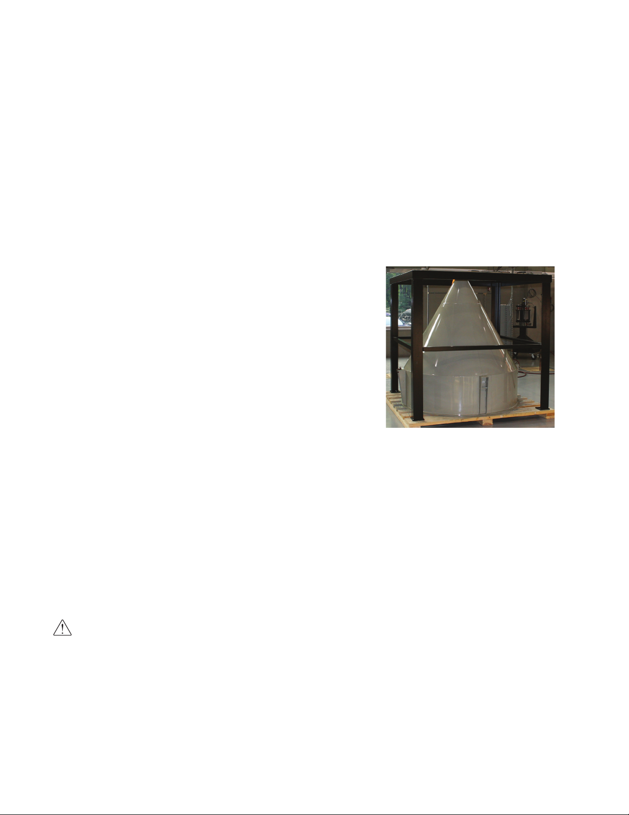
NOTE: For Drying Systems
supplied with “small” hoppers,
the floor stand and cone section
may be pre-assembled at the
factory. If your floor stand and
cone section are pre-assembled,
follow the instructions in this
section for mounting the floor
stand then proceed to the
instructions in the “Installing
the hopper door, Upper, and
Lid Sections” section of this
manual.
Tools for installation
UForklift, hoist, or crane;
and
UOther tools as dictated
by the specific installation.

Hopper Installation Guide I1-5
Installation of the HTC Control
(Models HTC 30, 60, and 90)
CAUTION: You are responsible for the structural integrity of this installation.
NOTE: The HTC control is shipped mounted on the left side of the Hopper floor stand on models
30, 60 and 90.
NOTE: If, by using your own provisions, you change the mounting arrangement of the control center to
a wall mount unit, it must be mounted six (6) inches {152.4 mm} off of the wall to provide clearance for
the heat sink.
HTC Control
Center
NOTE: If using a GasTrac for
the drying system heat source,
see “Installing the Hopper
Cone Section”
(Continued)

1-6 I Hopper Installation Guide
Installing the HTC Control (continued)
(Models HTC 120)
CAUTION: You are responsible for the structural integrity of this installation.
1 Securely bolt the HTC control to the left side of the floor stand. Use the supplied
locking fasteners to securely mount the HTC control center to the floor stand to
prevent vibration-induced loosening.
NOTE: If, by using your own provisions, you change the mounting arrangement of the control center to a
wall mount unit, it must be mounted six (6) inches {152.4 mm} off of the wall to provide clearance for the
heat sink.
Installing the HTC Control (continued)
(Models HTC 180 and 270)
CAUTION: You are responsible for the structural integrity of this installation.
1 Move the control center into
its final location for opera-
tion (see figure to the right).
The control center must be
positioned close enough to the
hopper to allow connection of
the RTD temperature probe.
The control center can be
mounted to a wall, the hopper
frame or a floor stand with
customer supplied provisions.
NOTE: If, by using your own provisions, you change the mounting arrangement of the control center to a
wall mount unit, it must be mounted six (6) inches {152.4 mm} off of the wall to provide clearance for the
heat sink.
NOTE: If the lengths of the
process and process
protection RTD wiring are
too short for your installation,
contact Conair Parts Depart-
ment (800.458.1960) to
purchase extension cables.
From outside the United States,
call (814.437.6861).
NOTE: If using a GasTrac for
the drying system heat source,
see “Installing the Hopper
Cone Section” HTC Control Center
(Free-Standing)
HTC Control
Center
(Continued)

Hopper Installation Guide I1-7
Location and Mounting of the HTC
Heater Assembly (Models HTC 30, 60, and 90)
CAUTION: You are responsible for the structural integrity of this installation.
NOTE: The HTC control is shipped mounted on the left side of the Hopper floor stand on models
30, 60 and 90. (see figure to the right)
NOTE: The heater is prewired to the control box on HTC Model 30, 60 and 90.
Location and Mounting of the HTC
Heater Assembly (Models HTC 120)
CAUTION: You are responsible for the structural integrity of this installation.
1 Securely bolt the HTC heater assembly to the back of the floor stand (see figure
to the right). Use the locking fasteners provided to securely mount the heater
assembly to the floor stand to prevent vibration-induced loosening.
NOTE: The heater is prewired to the control box on HTC Model 120.
Location and Mounting of the HTC
Heater Assembly (Models HTC 180 and 270)
CAUTION: You are responsible for the structural integrity of this installation.
1 Securely bolt the HTC heater assembly to the back of the floor stand
(see figure to the right). Use the locking fasteners provided to securely mount the
heater assembly to the floor stand to prevent vibration-induced loosening.
2 Refer to the wiring diagram to make the wiring connections for the heater
and control box. Only a qualified electrician should make the wiring connections
between the control and the heater. The customer must supply the appropriately-
sized wire and conduit to make connections.
IMPORTANT:
Always refer to the wiring
diagrams that came with
your HTC before making
electrical connections.
HTC Heater
CAUTION: Always
disconnect and lock out
the main power sources
before making electrical
connections. Electrical
connections should be
made only by qualified
personnel.
CAUTION: Check the
disconnect with a volt
meter to ensure that the
power is off.

1-8 I Hopper Installation Guide
Installing the Hopper Cone Section on
the Floor Stand Assembly
After the hopper floor stand assembly has been secured to the floor, install the hopper
cone section on the floor stand using the following steps.
IMPORTANT: You will need to consider the installation of your entire drying
system before permanently placing any system component.
1 Make sure any hoses, wires, etc. attached to the floor stand and cone section
(for shipping purposes), are positioned away from the mating surfaces of the
assemblies so they will not be damaged during this procedure.
2 Using a forklift, hoist, or crane, lift the cone section assembly above the floor
stand.
CAUTION: To prevent accident and injury, lift the cone and hopper sections onto
the floor stand assembly using a forklift, hoist, or crane.
3 Set the cone section on the floor stand as shown. Make sure the holes in the cone
section mounting lugs align with the holes in the top of the floor stand assembly.
4 Secure the cone section to
the floor stand assembly
using the four (4) sets of
1/2 inch - 13 hardware
supplied.
5 Take a moment to record
serial numbers and electrical
power specifications in the
blanks provided on the back
of the User Guide’s title page.
The information will be
helpful if you ever need
service or parts.
6 You are now ready to
continue installation. Follow
the preparation steps in the
next section.
Tools for installation
UForklift, hoist, or crane; and
UOther tools as dictated
by the specific installation.
NOTE: For drying systems
supplied with “small” hoppers,
the floor stand and cone
section may be pre-assembled
at the factory. If your floor stand
and cone section are pre-
assembled and you have
secured the floor stand to the
floor, proceed to the instructions
in the “Installing the Hopper
Door, Upper, and Lid
Sections” section of this
manual.

Hopper Installation Guide I1-9
Installing the Hopper Door, Upper, and
Lid Sections
Spreader Cone Weldment
1 Prepare to assemble the spreader cone weldment.
Make sure hopper cone section is assembled on the floor stand.
2 Install the spreader cone
weldment in the hopper cone
section by sliding it through the
top of the cone section and down
around below the inlet tube.
3 Insert the spreader cone weldment
into the air inlet tube aligning the
slot with the pin.
4 Insert the spreader cone weldment
fully into the air inlet tube.
5 Rotate the spreader cone weldment
clock-wise until it stops. Pull it
down into position.
NOTE: The spreader cone weldment should
rest on the air inlet tube pin.

1-10 I Hopper Installation Guide
Installing the Hopper Door, Upper, and
Lid Sections
IMPORTANT: Before installing the hopper door, upper (if applicable), and lid
sections of the hopper, careful consideration should be given to the following:
•When installing the hopper door section, make sure the hopper door is positioned to
allow easy access into the hopper to aid in installation and to facilitate hopper
cleaning and maintenance in the future.
•When installing the hopper lid section, make sure to identify the location of the
hopper’s return air outlet. The lid section has multiple piping options that can be
connected to an optional cyclone or traditional hopper outlet, then to an optional dust
collector and finally to the dryer’s return air inlet. Consider all piping/ hosing
possibilities when installing the dryer, heater (gas or electric), optional dust collector
and optional cyclone before making the installation permanent.
Hopper Door Section
To install the hopper door section:
1 Apply strip and stick gasket around the flange on the top of the cone section.
NOTE: The strip and stick gasket is supplied with the hopper.
NOTE: Thoroughly clean all flanges with alcohol or similar product before installing the
strip and stick gasket.
2 Using a forklift, hoist or crane, lift the hopper door section assembly above the
cone section.
CAUTION: To prevent accident and injury, lift the hopper door section onto
the cone section using a forklift, hoist or crane.
NOTE: When applying the strip
and stick gasketing material,
do not cover the holes in the
cone section flange. Apply the
strip and stick gasketing
material around the holes so
you will have a good seal but
not interfere with the mounting
hardware that will be used to
secure the hopper door section
to the cone section.
Tools for installation
UForklift, hoist, or crane;
and
UOther tools as dictated
by the specific installation.
(Continued)
TIP: Conair recommends
applying strip and stick
gasketing material 1/4 inches
{6.35 mm} from the inside to
the edge of the hopper.

Hopper Installation Guide I1-11
Installing the Hopper Door, Upper, and
Lid Sections (continued)
Hopper Door Section (continued)
3 Set the hopper door section on the
cone section. As the hopper door
section is positioned on the cone
section, make sure the holes in the
hopper door section align with the
holes in the cone section.
4 Secure the hopper door section to
the cone section using the 3/8-inch
hardware supplied.
(Continued)
CAUTION: Keep
hands clear of sections
coming together.

1-12 I Hopper Installation Guide
NOTE: When applying the strip
and stick gasketing material, do
not cover the holes in the cone
section flange. Apply the strip
and stick gasketing material
around the holes so you will
have a good seal but not inter-
fere with the mounting hard-
ware that will be used to
secure the hopper door section
to the cone section.
TIP: Conair recommends
applying strip and stick
gasketing material 1/4 inches
{6.35 mm} from the inside to
the edge of the hopper.
Installing the Hopper Door, Upper, and
Lid Sections (continued)
Hopper Upper Section(s) (If Applicable)
1 Apply the supplied strip and stick gasket around the flange on the top of the
hopper door section.
2 Using a forklift, hoist, or crane, lift the hopper upper section assembly above the
hopper door section.
CAUTION: To prevent accident and injury, lift the hopper upper section onto
the hopper door section using a forklift, hoist, or crane.
CAUTION: Keep hands clear of sections coming together.
IMPORTANT: Line up the sight glasses of the hopper upper section(s) with the
sight glasses of the hopper door section.
3 Set the hopper upper section on the hopper door section. As the hopper upper
section is positioned on the hopper door section, make sure the holes in the upper
section align with the holes in the door section.
4 Secure the hopper upper section to the hopper door section using the 3/8-inch
hardware supplied.
NOTE: If more than one (1) hopper upper section is to be installed, repeat the steps detailed in this
section for each hopper upper section.
(Continued)

Hopper Installation Guide I1-13
(Continued)
Installing the Hopper Door, Upper, and
Lid Sections (continued)
Hopper Lid Section
IMPORTANT: Improper mounting of the hopper lid will cause interference when
installing the DM-II monitor probe and optional integrated cyclone.
To install the hopper upper section(s):
1 Apply the supplied strip and
stick gasketing material around
the flange on the top of the
hopper door or hopper upper
section (whichever is applicable).
2 Using a forklift, hoist, or crane,
lift the hopper lid section
assembly above the hopper door
or hopper upper section.
3 Set the hopper lid section on
the hopper door or hopper
upper section as shown. As the
hopper lid section is positioned on
the hopper door or hopper upper
section, make sure the holes in
the hopper lid section align with
the holes in the hopper door or
hopper upper section.
4 Secure the hopper lid section to
the hopper door or hopper upper
cone section using the 3/8-inch
hardware supplied.
NOTE: When applying the strip
and stick gasketing material,
do not cover the holes in the
hopper door section flange.
Apply the strip and stick gasket-
ing material around the holes
so you will have a good seal
but not interfere with the
mounting hardware that will
be used to secure the hopper
upper section to the hopper
door section.
TIP: Conair recommends
applying strip and stick
gasketing material 1/4 inches
{6.35 mm} from the inside to the
edge of the hopper.
WARNING: To
accomplish the following
steps, it may be necessary
for personnel to enter the
hopper assembly. If it is
necessary to enter the
hopper assembly, all appli-
cable OSHA procedures for
working within a confined
space MUST BE followed.
CAUTION: To pre-
vent accident and injury,
lift the hopper upper
section onto the hopper
door section using a
forklift, hoist, or crane.
CAUTION: Keep
hands clear of sections
coming together.

Page intentionally left blank

Hopper Installation Guide I2-1
2
SECTION
2
Accessories
Accessories
Ladder and Handrail Installation ............................ .2-2
Drop Tube (Hopper Air Outlet) Installation ............... .2-5
Installing the Cyclone (optional) ............................. 2-6
Installing the Drying Monitor Probe ........................ 2-9
HP Heater Pack Installation (If applicable) ..............2-11
Installing the Receiver(s), Purge Valve,
Modular Distribution Box(es), Loader (optional)........2-18
Location and Mounting of
the Dust Collector (optional) .................................2-19
Location and Mounting of
Vacuum Pump(s) (optional)) ..................................2-20

2-2 I Hopper Installation Guide
Ladder and Handrail Installation
CAUTION: To prevent accident and injury, lift
the hand rail onto the upper section of the hopper
using a forklift, hoist, or crane.
The design of the ladder and handrail is such that it
is to be installed 180°from the hopper door location,
typically towards the back of the hopper.
The hopper lid,
Cyclone Dust
Collector and
the air outlet needs
to be rotated to
interface with the
openings in the
handrail.
Handrail Installation
The handrail can be installed in one of two ways:
•On to a completely assembled hopper.
•During the hopper assembly process.
Installing on a Completely
Assembled Hopper
1 Position the hopper lid to allow the
air outlet to pass through as shown in
the picture.
2 If installed, remove any items
mounted to the hopper lid.
3 Remove mounting hardware holding
the hopper lid to the hopper body.
4 Locate the handrail and twenty four
(24) 3/8-16 inch x 2 1/2 inch
mounting bolts.
5 Lift handrail onto the top of the
hopper, position as required.
6 Install, fasten and tighten all bolts and nuts too firmly secure
handrail installation.
Tools for installation
UForklift, hoist, or crane;
and
UOther tools as dictated
by the specific installation.
(Continued)
This manual suits for next models
1
Table of contents
Other Conair Industrial Equipment manuals

Conair
Conair S Series User manual

Conair
Conair CBW 1012 User manual

Conair
Conair DeDuster C-50 User manual

Conair
Conair Viper User manual

Conair
Conair CG-1436 User manual

Conair
Conair TF Series User manual

Conair
Conair GT420 User manual

Conair
Conair SHH Series User manual

Conair
Conair Air Wash 50 User manual