Interroll SH 1100 User manual
INSPIRED BY EFFICIENCY
Installation and Operating Instructions
Interroll Module belt conveyor - straight
SH 1100
Rated width 405 mm (S), 710 mm (M), 862 mm (L)
Version 1.0 (06/2022) en
Translation of original operating instructions

Manufacturer's address
Interroll Trommelmotoren GmbH
Center of Excellence Hygienic Solutions
Opelstraße 3
41836 Hueckelhoven/Baal (Germany)
www.interroll.com
Interroll Service
Our Service Team will gladly provide advice in case of questions or problems:
Hotline: +49 (0) 2193 - 23 222
E-mail: [email protected]
Contents
We strive for the information presented to be correct, up to date and complete. We have
carefully developed the contents of this document. Nevertheless, errors and changes are
expressly subject to change.
Copyright / intellectual property right
Texts, images, graphics and the like as well as their arrangement are protected by
copyright and other protection laws. Reproduction, modification, transfer or publication
of any part or the entire content of the document in any form is prohibited. This
document is intended exclusively for information purposes and for intended use and does
not authorize replicating the respective products. All signs contained in this document
(registered trademarks, such as logos and business designations) are the property of
Interroll Trommelmotoren GmbH or third parties and may not be used, copied or
distributed without prior written consent.
Interroll T. Nr. 1131893
Version 1.0 (06/2022) en
Translation of original operating instructions

Interroll Module belt conveyor SH 1100
Version 1.0 (06/2022) en
Translation of original operating instructions
3
Table of contents
Introduction............................................................................................................................ 6
Notes about working with the installation and operating instructions...................................... 6
Contents of these installation and operating instructions ...................................................... 6
Integrated part of the product ...................................................................................................... 6
Installation and operating instructions are part of the module............................................ 6
Warning notices in this document........................................................................................................ 7
Symbols....................................................................................................................................................... 7
Safety ..................................................................................................................................... 8
State of the art ......................................................................................................................................... 8
Intended use .............................................................................................................................................. 8
Field of use.......................................................................................................................................... 8
Changes to the module ................................................................................................................... 8
Unintended use......................................................................................................................................... 9
Personnel qualification ............................................................................................................................ 9
Operators............................................................................................................................................ 9
Service personnel.............................................................................................................................. 9
Electricians........................................................................................................................................... 9
Personal protective equipment ............................................................................................................. 10
Dangers ...................................................................................................................................................... 11
Safety devices.................................................................................................................................... 11
Heat ...................................................................................................................................................... 11
Electricity.............................................................................................................................................. 11
Rotating parts..................................................................................................................................... 11
Parts lying around or falling off .................................................................................................... 11
Risk of injury due to faults during operation.............................................................................. 11
Insufficient hygiene............................................................................................................................ 11
Maintenance intervals............................................................................................................................. 11
Interfaces to other devices .................................................................................................................... 12
Operating modes..................................................................................................................................... 12
Normal mode..................................................................................................................................... 12
Special mode...................................................................................................................................... 12
Product identification ........................................................................................................... 13
Module belt conveyor - straight (SH 1100)...................................................................................... 13
Components........................................................................................................................................ 13
Property ............................................................................................................................................... 14
Technical data .................................................................................................................................... 15
Scope of supply........................................................................................................................................ 17
Nameplate................................................................................................................................................. 17
Transport and storage .......................................................................................................... 18
Transport..................................................................................................................................................... 18
After the delivery .............................................................................................................................. 18
Storage....................................................................................................................................................... 18

Interroll Module belt conveyor SH 1100
Table of contents
4 Version 1.0 (06/2022) en
Translation of original operating instructions
Installation ............................................................................................................................. 19
To be observed during installation...................................................................................................... 19
Electrical installation ......................................................................................................................... 19
Torque................................................................................................................................................... 20
Grounding........................................................................................................................................... 20
Orientation.......................................................................................................................................... 20
Connection.......................................................................................................................................... 20
Anchoring............................................................................................................................................ 20
Integration into complete system .................................................................................................. 20
Installing supports .................................................................................................................................... 21
Integrating the module in a complete system................................................................................... 22
Installing the universal support............................................................................................................. 23
Installing the side guide.......................................................................................................................... 25
Installing the photo cell and reflector................................................................................................. 26
Installing the photo cell.................................................................................................................... 27
Installing the reflector....................................................................................................................... 28
Connecting the modules......................................................................................................................... 29
Straight roller conveyor - straight module belt conveyor (80) ............................................. 30
Roller curve - straight module belt conveyor (80).................................................................... 31
Straight module belt conveyor (50) - roller curve.................................................................... 32
Straight module belt conveyor (50) - straight roller conveyor ............................................. 33
Straight module belt conveyor (50) - straight module belt conveyor (50)........................ 34
Straight module belt conveyor (80) - straight module belt conveyor (50)........................ 35
Module belt curve - front straight module belt conveyor (50) ............................................. 36
Straight module belt conveyor (50) - lateral diverter............................................................. 37
Lateral diverter - straight module belt conveyor (80) ............................................................. 38
Straight module belt conveyor (80) - front diverter ................................................................ 40
Front diverter - straight module belt conveyor (50) ................................................................ 41
Straight module belt conveyor (50) - transfer module ........................................................... 42
Initial startup and operation................................................................................................ 43
Initial startup.............................................................................................................................................. 43
Operation .................................................................................................................................................. 44
Before every operation start.......................................................................................................... 44
During operation............................................................................................................................... 44
Procedure in case of accident or fault ........................................................................................ 44
Cleaning................................................................................................................................. 45
Preparation for cleaning by hand....................................................................................................... 46
Manual cleaning....................................................................................................................................... 46
Resistance................................................................................................................................................... 48
Maintenance and repair ...................................................................................................... 49
Observe the following for maintenance and repair ...................................................................... 49
Maintenance intervals............................................................................................................................. 50
Maintenance and inspection list........................................................................................................... 50
Preparatory and follow-up maintenance work ............................................................................... 51
Removing/installing cover plates at return axles...................................................................... 52
Removing/installing contact guard and covers at center drive station.............................. 53

Interroll Module belt conveyor SH 1100
Table of contents
Version 1.0 (06/2022) en
Translation of original operating instructions
5
Removing/installing head drive cable connection cover........................................................ 54
Removing/installing center drive cable connection cover...................................................... 54
Removing/installing drum motor end plate................................................................................ 55
Removing/installing front side idler axle end plate ................................................................. 56
Replacing the module conveyor........................................................................................................... 57
Replacing the module conveyor (head drive)............................................................................ 57
Replacing the module conveyor (center drive).......................................................................... 58
Replacing rollers/axles............................................................................................................................ 59
Replacing the center drive station ................................................................................................ 60
Replacing the drum motor (head drive)...................................................................................... 62
Removing/installing holder from/on the drum motor (head drive) ..................................... 63
Removing/installing drum motor (center drive)......................................................................... 64
Replace the sprockets....................................................................................................................... 66
Replacing the return axle................................................................................................................ 67
Replacing the front idler axle......................................................................................................... 68
Replacing sliding guides ......................................................................................................................... 69
Replacing the photo cell and reflector............................................................................................... 71
Replacing the photo cell.................................................................................................................. 71
Replacing the reflector..................................................................................................................... 72
Troubleshooting..................................................................................................................... 73
In case of a fault....................................................................................................................................... 73
Troubleshooting ........................................................................................................................................ 73
Spare and wear parts .......................................................................................................... 75
Ordering information.............................................................................................................................. 75
SH 1100 with head drive...................................................................................................................... 76
Spare parts drawing of SH 1100 with head drive ................................................................. 76
Spare parts list of SH 1100 with head drive ............................................................................ 77
SH 1100 with center drive.................................................................................................................... 79
Spare parts drawing of SH 1100 with center drive ............................................................... 79
Spare parts list of SH 1100 with center drive.......................................................................... 80
Decommissioning and disposal .......................................................................................... 81
Environmental protection regulations................................................................................................. 81
Declaration of incorporation ............................................................................................... 82
Declaration of incorporation ............................................................................................... 84
Appendix ............................................................................................................................... 86
Warranty for Interroll module belt conveyors ................................................................................. 86
Restrictions........................................................................................................................................... 86
Exceptions............................................................................................................................................ 86
Interroll Service......................................................................................................................................... 86

Interroll Module belt conveyor SH 1100
6 Version 1.0 (06/2022) en
Translation of original operating instructions
Introduction
Notes about working with the installation and operating instructions
The Interroll Modulbandförderer - gerade product is generally referred to as "module" in this
document.
Contents of these
installation and operating
instructions
These installation and operating instructions contain important notes and information about the
various operating phases of the module:
• Transport, assembly and startup
• Safe operation, required maintenance tasks, removal of any faults
• Spare parts, supplementary accessories
Integrated part of the
product
The installation and operating instructions describe the module at the time of its initial delivery
after manufacturing.
In addition to these installation and operating instructions, special contractual agreements and
technical documents apply to special versions of the module and its additional equipment.
Installation and operating
instructions are part of the
module
4To ensure trouble-free and safe operation, as well as the settlement of possible warranty
claims, always read these installation and operating instructions first and observe all
information contained herein.
4Keep the installation and operating instructions close to the module.
4Pass the installation and operating instructions on to any subsequent operator or occupant.
Interroll does not accept any liability for faults or defects due to non-observance of these
installation and operating instructions.
4If you have any questions after reading the installation and operating instructions, please
contact Interroll customer service. Contact persons near you can be found on the Internet
under: www.interroll.com/contact.

Interroll Module belt conveyor SH 1100
Introduction
Version 1.0 (06/2022) en
Translation of original operating instructions
7
Warning notices in this document
The warning notices refer to risks which may arise while using the module. They are available in
four danger levels identified by the signal word:
Signal word Meaning
DANGER Identifies a danger with high risk that will result in death or serious injury if
it is not avoided.
WARNING Identifies a danger with medium risk that could result in death or serious
injury if it is not avoided.
CAUTION Identifies a danger with low risk that may result in minor or medium injury
if it is not avoided.
NOTICE Identifies a danger that results in property damages.
Symbols
This symbol marks useful and important information.
Requirement:
RThis symbol represents a prerequisite to be met prior to installation and maintenance work.
4This symbol marks the steps to be carried out.

Interroll Module belt conveyor SH 1100
8 Version 1.0 (06/2022) en
Translation of original operating instructions
Safety
State of the art
The module has been built to comply with the state of the art. Nevertheless, users may encounter
hazards during its use.
Disregarding the notices in these installation and operating instructions may lead to life-
threatening injuries!
4Carefully read the installation and operating instructions and follow their content.
4Observe local accident prevention regulations and general safety regulations that apply in
the area of use.
Intended use
The module may only be used for industrial applications and in an industrial environment to
convey belt conveyor-ready goods, such as all types of boxes, packaged food or beverage units.
The module is an incomplete machine and must be integrated into a complete system prior to
operation.
Field of use The module is dimensioned only for a certain field of use and may not be operated outside of
these specific limits. For additional information, see the chapter "Technical Data".
Any other use is considered inappropriate. Deviating operating conditions require additional
clarifications, a special release of the module and new contractual agreements.
Changes to the module Any modifications that affect the safety are not permitted.

Interroll Module belt conveyor SH 1100
Safety
Version 1.0 (06/2022) en
Translation of original operating instructions
9
Unintended use
Any use beyond the intended use is considered inappropriate or, if required, must be authorized
by Interroll Trommelmotoren GmbH. Setup and operation in explosive atmospheres is prohibited.
The use in a medical-pharmaceutical area requires the approval from Interroll.
The transport of persons is prohibited.
The transport of hazardous or damaging goods is prohibited.
The transport of hot or hygroscopic goods is prohibited.
Installation in unprotected rooms exposed to the weather or in areas where the technology
deteriorates and can fail due to the prevailing climatic conditions is considered inappropriate
use.
Use of the module is not intended for private end customers! Use in a residential area is
prohibited without additional assessment and without the use of EMC protective measures that
have been adapted accordingly!
Personnel qualification
Unqualified personnel cannot recognize risks and, as a result, is subject to greater dangers.
4Authorize only qualified personnel to perform the activities described in these instructions.
4The operating company must ensure that personnel follow locally applicable regulations and
rules about safety and hazards while working.
The following target groups are addressed in these instructions:
Operators Operators have been instructed in the operation and cleaning of the module and follow the
safety guidelines.
Service personnel The service personnel features a technical training and performs the maintenance and repair
tasks.
Electricians Persons working on electrical installations must have pertinent technical training.

Interroll Module belt conveyor SH 1100
Safety
10 Version 1.0 (06/2022) en
Translation of original operating instructions
Personal protective equipment
4For all work, such as assembly, maintenance and cleaning tasks, wear personal protective
equipment that is suitable and appropriate for the hazard situation.
Close-fitting work clothing
Protective gloves
Safety shoes
Hard hat
Hearing protection

Interroll Module belt conveyor SH 1100
Safety
Version 1.0 (06/2022) en
Translation of original operating instructions
11
Dangers
The following list informs you about the various types of danger or damage that may occur
while working with the module.
Safety devices 4Perform any maintenance and repair work on the module only when it is powered down and
ensure that it cannot be started accidentally.
4In an area frequented by people or if people can reach between conveying goods, take
additional protective measures.
4Do not remove protective covers or housing.
4Regularly check the safety devices.
Heat 4Do not touch the drum motor during operation. Risk of burns.
Electricity 4Reach into the module only if the module is de-energized.
Rotating parts 4Never wear loose clothing.
4Never wear jewelery, such as necklaces or bracelets.
4If you have long hair, always wear a hair net.
Parts lying around or
falling off
4Remove equipment or material which is not required from the workspace.
4Wear safety shoes.
4Specify and monitor careful placement of the goods on the conveyor.
Risk of injury due to faults
during operation
4Regularly check the module for visible damage.
4Stop the module at once and ensure that it cannot be started accidentally in case of:
Smoke from a fire, unusual noise, blocked or defective conveying good, defective supports,
side guides or accessory devices, unauthorized removal of safety covers.
4Promptly have qualified personnel determine the cause of the fault.
4Immediately remove any escaping gear oil.
4Do not step onto the module during operation.
Insufficient hygiene 4Clean the module regularly.
4Follow all notices relevant to hygiene in these instructions.
Maintenance intervals
4Regularly perform maintenance and inspection work.
4Use only OEM spare parts.

Interroll Module belt conveyor SH 1100
Safety
12 Version 1.0 (06/2022) en
Translation of original operating instructions
Interfaces to other devices
Hazard locations may occur while integrating the module into a complete system. These are not
part of this manual and have to be analyzed during the installation and startup of the complete
system.
4When combining the module with other modules or machinery, check for new hazard
locations before startup.
4If necessary, take further construction measures.
Operating modes
Normal mode The module is installed at the customer in a complete system and operated as part of the system.
Special mode Special operation refers to all operating modes that are required to guarantee and maintain
regular operation.
Special operating mode Explanation Comment
Transport/storage Loading and unloading, transport and storage -
Assembly/initial startup Installation at the end customer and performing the test run -
Cleaning External cleaning without removing protective devices When powered down
Maintenance/repairs Maintenance and inspection tasks When powered down
Troubleshooting Troubleshooting in the event of a fault -
Fault elimination Eliminating the fault When powered down
Decommissioning Removal from the complete system When powered down
Disposal Removal from the complete system and disassembly When powered down

Interroll Module belt conveyor SH 1100
Version 1.0 (06/2022) en
Translation of original operating instructions
13
Product identification
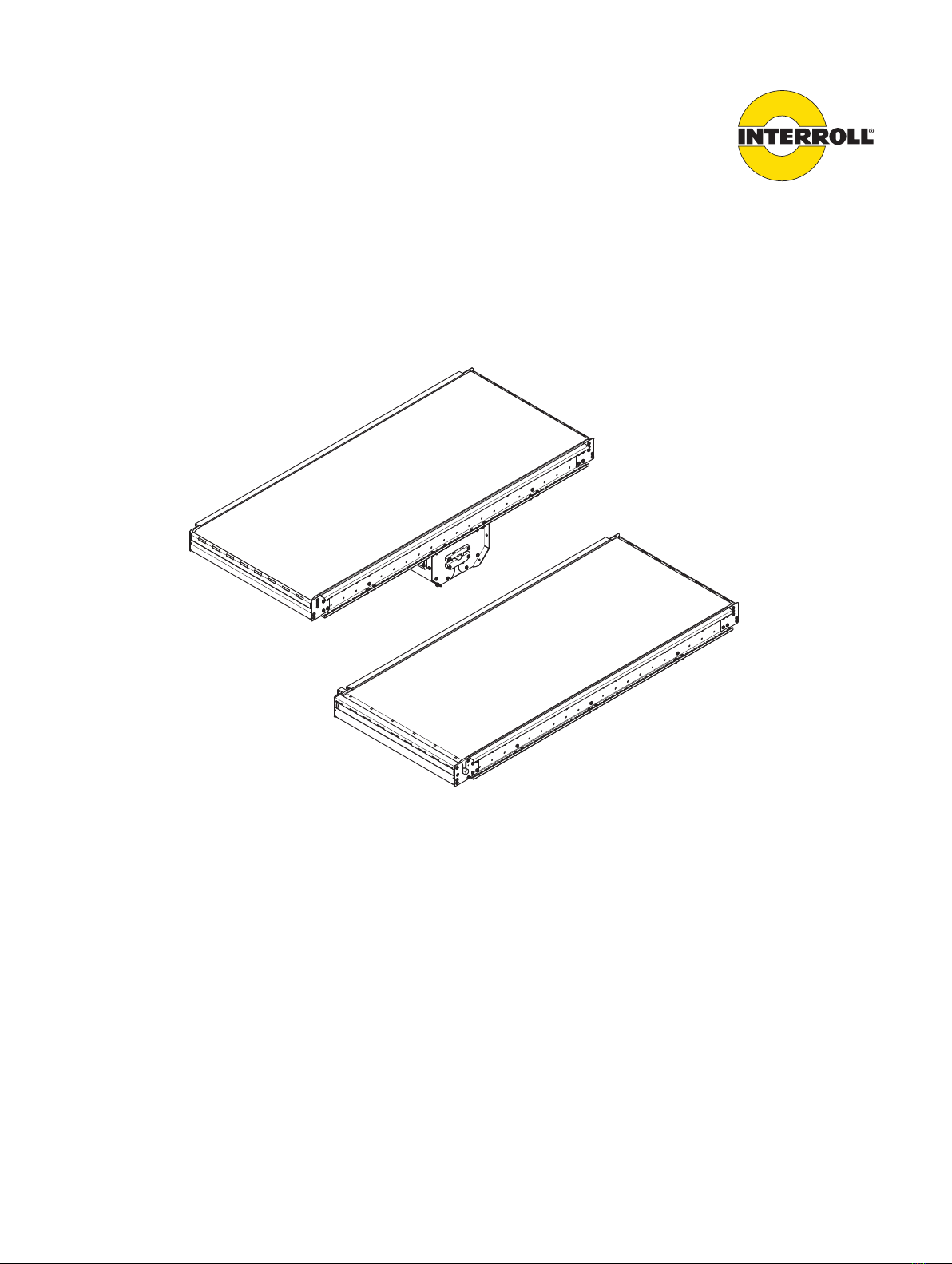
Module belt conveyor - straight (SH 1100)
The Interroll straight module belt conveyor is available in the following rated widths (BF):
• S: 405 mm
• M: 710 mm
• L: 862 mm
as well as in the following drive variants:
• SH 1100 HD (Head Drive)
• SH 1100 CD (Center Drive)
Components The straight module belt conveyor SH 1100 consists of the central ascending belt and features
neither upper arch nor feed belt.
1
54 6 7 8
32
10 911
Straight module belt conveyor head drive SH 1100 HD with drum motor (top view)
1 Cable output protective cover 7 End plate
2 Head drive drum motor 8 Front idler axle
3 Outside sliding guide 9 Side frame
4 Inside sliding guide 10 Return axle cover plate
5 Return axle 11 Head drive cover
6 Module conveyor
1 2 2 2 3
Straight module belt conveyor head drive SH 1100 HD with drum motor (side view)
1 Head drive drum motor 3 Front idler axle
2 Return axle

Interroll Module belt conveyor SH 1100
Product identification
14 Version 1.0 (06/2022) en
Translation of original operating instructions
53 4 1
21
8 7 695
Straight module belt conveyor center drive SH 1100 CD with drum motor (top view)
1 Front idler axle 6 Side frame
2 Outside sliding guide 7 Return axle
3 Inside sliding guide 8 Drive station
4 Return axle cover plate 9 Module conveyor
5 End plate
1 2 3 34 2 1
Straight module belt conveyor center drive SH 1100 CD with drum motor (side view)
1 Front idler axle 3 Idler pulley
2 Return axle 4 Drum motor
Property The module belt conveyor is used for the transport of goods that are not suitable for roller
tracks, and for all types of goods on inclines and declines.
The module belt conveyor is available with drum motor as center drive (CD) or as head
drive (HD).
A frequency inverter can be used as an option. Observe the installation guidelines of the
frequency inverter manufacturer (e.g. the frequency inverter from Getriebebau Nord).

Interroll Module belt conveyor SH 1100
Product identification
Version 1.0 (06/2022) en
Translation of original operating instructions
15
Technical data SH 1100 HD
Rated width (BF) 405 mm (S)
710 mm (M)
862 mm (L)
Conveying width (CW)
Dimensions of conveying good Min.: 100 x 100 mm
Max.: 700 x 800 mm
Max. load capacity 35 kg/m
Conveyor speed 0.1 to 0.8 m/s
Ambient temperature –5 to +40 °C
Incline/decline -6 to -18°; +6 to +18°
Angle adjustability In increments of 3°
Max. module length Preselected in the layouter
Conveying height (TOB) Preselected in the layouter
Number of zones (N) 1
Motor type Synchronous drum motor DM 0080
Rated voltage 230/400 V 50 Hz
230/460 V 60 Hz
Electrical power 550 W
Drive system Head drive (HD)
Transmission of force Sprockets
Frequency inverter Standard: Getriebebau Nord
Module conveyor Ammeraal M-QNB-C
Side frame hole spacing 90 mm
Reversibility No
Protection rating Drum motor: IP 69 K
Frequency inverter: IP 20 or IP 66

Interroll Module belt conveyor SH 1100
Product identification
16 Version 1.0 (06/2022) en
Translation of original operating instructions
SH 1100 CD
Rated width (BF) 405 mm (S)
710 mm (M)
862 mm (L)
Conveying width (CW)
Dimensions of conveying good Min.: 100 x 100 mm
Max.: 700 x 800 mm
Max. load capacity 35 kg/m
Conveyor speed 0.1 to 0.8 m/s
Ambient temperature –5 to +40 °C
Incline/decline -6 to -18°; +6 to +18°
Angle adjustability In increments of 3°
Max. module length Preselected in the layouter
Conveying height (TOB) Preselected in the layouter
Number of zones (N) 1
Motor type Synchronous/asynchronous drum motor
DM0080, DM0113, DM0138, DM0165
Rated voltage 230/400 V 50 Hz
230/460 V 60 Hz
Electrical power 550 to 1818 W
Drive system Center drive (CD)
Transmission of force Sprockets
Frequency inverter Standard: Getriebebau Nord
Module conveyor Ammeraal M-QNB-C
Side frame hole spacing 90 mm
Reversibility Yes
Protection rating Drum motor: IP 69 K
Frequency inverter: IP 20 or IP 66

Interroll Module belt conveyor SH 1100
Product identification
Version 1.0 (06/2022) en
Translation of original operating instructions
17
Scope of supply
The module is delivered completely assembled.
The scope of delivery includes:
• Rack, including side frames, sliding guides and guide rails
• Drive (drum motor as center drive or head drive)
• Rollers/axles (return axles, front side idler axle, idler pulley)
• Module conveyor
• Covers and end plates
Optional:
• Photo cell and reflector, sensor holder and universal support
• Side guides, side guide brackets and universal support
• Connector sets incl. module connectors and contact guards
• Frequency inverter (e.g. from Getriebebau Nord)
• Electronics
• Supports
The side guide profiles and sensors are delivered installed (if ordered).
Nameplate
Conveyor Type
Interroll Trommelmotoren GmbH
Center of Excellence Hygienic Solutions
Opelstraße 3
41836 Hueckelhoven/Baal (Germany)
www.interroll.com
TypePlate
Level
Layout Position .No.
Sales Order No. / Pos. Serial Number
Build Year
Weight [kg]
10
4
1
3
2
5
7
8
9
6
Nameplate
1 Arrow in transport direction 6 Machine number
2 Company address 7 Serial number
3 Type designation 8 QR code
4 Level 9 Year of manufacture
5 Layout item no. 10 Weight in kg
The information on the nameplate is used to identify the conveyor. The type designation is
required to use the conveyor according to its intended use.
The nameplate is located on the right side frame.

Interroll Module belt conveyor SH 1100
18 Version 1.0 (06/2022) en
Translation of original operating instructions
Transport and storage
Transport
WARNING
Risk of injury during transport
4Fasten the module securely and slip-proof for transport.
4Ensure that the lifting device (e.g. fork lift) is rated for the weight of the module.
4Ensure that there are no persons under the suspended load while lifting and moving the
module.
4Have any persons leave the danger zone.
4Wear safety shoes.
4Check correct fastening for transport.
4Avoid strong impacts during transport.
4Do not expose the module to strong temperature fluctuations since these could damage the
electrical components.
Loosen the transport locks around the package. The crossbeams above the top module can then
be removed, thereby exposing the module. The individual module is lifted out of the package
using a suitable lifting device.
After the delivery 4Inspect module for transport damages.
4Immediately notify the carrier and manufacturer in case of damages to avoid losing any
claims for compensation.
Storage
WARNING
Risk of injury due to improper storage
4Do not stack modules. Do not place any other objects on the module.
4Check module for stability.
4If the module is not immediately placed in operation, store it at a location protected against
humidity and dust.
Interroll Module belt conveyor SH 1100
Version 1.0 (06/2022) en
Translation of original operating instructions
19
Installation
WARNING
Risk of injury due to improper assembly
4Mechanical assembly tasks should be performed only by service personnel. Observe the
safety information.
4Electrical assembly tasks should be performed only by authorized electricians. Observe the
safety information.
4Carefully install all terminals and connections, such as cables, hoses and pipework, and
check for correct fit.
The module is delivered to the installation site as a pre-assembled unit and must be set up,
connected and integrated into a system on site.
If available, photo cell and reflector are already pre-assembled and connected. The side guides
(universal support, side guide brackets and side guides) are also delivered assembled.
The installation tasks are divided into two sections:
• Setting up the module
• Integrating the module into a complete system
To be observed during installation
Electrical installation
DANGER
Danger - energized cable ends!
4Electrical installation should only be performed by qualified electricians.
4Ensure that the device is powered down.
4Minimum bending radii of cables, hoses and lines must be maintained.
DANGER
Danger to life from electrocution and crushing
Installation and maintenance tasks on 400-V conveyor systems while they are in operation can
cause life-threatening electrocution and serious crushing.
4Power down the entire conveyor module and ensure that it cannot be started accidentally.

Interroll Module belt conveyor SH 1100
Installation
20 Version 1.0 (06/2022) en
Translation of original operating instructions
The module is provided with voltage either via CEE plug or direct installation in the control
cabinet.
4Check cables and components for damage before installation.
4The connection values of the module are listed on the motor nameplate.
Static electricity
Take proper measures for grounding and potential equalization.
Use only original fuses with specified amperage.
Torque When tightening screws and nuts, always observe the standard tightening torque, unless
specifically indicated otherwise. Standard screw lockers should be replaced as needed.
Grounding During installation of the module, its grounding must be ensured. A grounding connection, which
is fastened at the supports, is intended for this purpose. It is recommended to connect a
grounding connection with grounding cable every 20 m.
Orientation 4Align the module using the height-adjustable feet of the support. The roller top edge (for
roller conveyors) or the module conveyor top edge (for module belt conveyors) is the
relevant height for aligning the modules. Use suitable tools for the alignment (spirit level or
rotation laser).
4Secure the adjusted height.
4During alignment of the module, ensure that no moving parts are touching.
Connection 4Connect the individual modules with each other using the profile connector.
4During the setup of the module, check the passageways for the personnel. Install transitions
as necessary.
Anchoring 4Anchor or fasten the module torsion-free, e.g. to the floor or to adjacent components.
Integration into complete
system
4When integrating the module into the complete system, consider possible danger spots,
particularly infeed locations and interfaces.
Table of contents
Other Interroll Industrial Equipment manuals


