Trelawny 540.2030 User manual

CONCRETE GRINDER
Original instructions
540.2030 • 540.2040
TCG 180L • TCG 180
9
78
1
11
6
10
2
4
3
5
13
12
12

3
Original instructions
EN
Contents
Introduction........................................................................................................................................................................................... 3
Technical specications .................................................................................................................................................................... 5
General power tool safety warnings............................................................................................................................................... 6
Concrete grinder safety warnings.................................................................................................................................... 7
Know your product ............................................................................................................................................................ 7
Operation............................................................................................................................................................................ 8
Maintenance ...................................................................................................................................................................... 9
UNPACKING
Due to modern mass production techniques, it is unlikely that your power tool is faulty or that a part is missing. If you nd
anything wrong, do not operate the tool until the parts have been replaced or the fault has been rectied. Failure to do
so could result in serious personal injury.
ASSEMBLY
The concrete grinder is packed fully assembled except for the diamond cup wheel.
Introduction
Your new TRELAWNY power tool will more than satisfy your expectations. It has been manufactured under stringent
TRELAWNY Quality Standards to meet superior performance criteria. You will nd your new tool easy and safe to
operate, and, with proper care, it will give you many years of dependable service.
WARNING:
Carefully read through these original instructions before using your new TRELAWNY power tool Take special
care to heed the Warnings. Your TRELAWNY power tool has many features that will make your job faster and
easier. Safety, performance, and dependability have been given top priority in the development of this tool,
making it easy to maintain and operate.
Do not dispose of electrical products together with household waste!
Waste electrical products should not be disposed of with household waste. Please recycle where facilities
exist. Check with your local authority or retailer for recycling advice.
ENVIRONMENTAL PROTECTION
The machine, accessories and packaging should be sorted for environmental-friendly recycling.
The plastic components are labelled for categorised recycling.

4
TCG 180L • TCG 180
EN
DESCRIPTION OF SYMBOLS
The rating plate on your tool may show symbols. These represent important information about the product or instruc-
tions on its use.
Double insulated for additional protection
Spindle thread: M14
Conforms to the relevant European Directives
Refer to original instructions
YYYY-Www Production period, where the variable symbols are:
YYYY - year of manufacture, ww - calendar week number
5
Original instructions
EN
Technical specications
Model TCG 180L TCG 180
Part Number 540.2030 540.2040
Voltage 110V~ 5 0Hz 230V~50Hz
Power input 2000 W 2600 W
No load speed 6500 min-1 6500 min-1
Spindle thread M14 M14
Spindle thread length 20 mm 20 mm
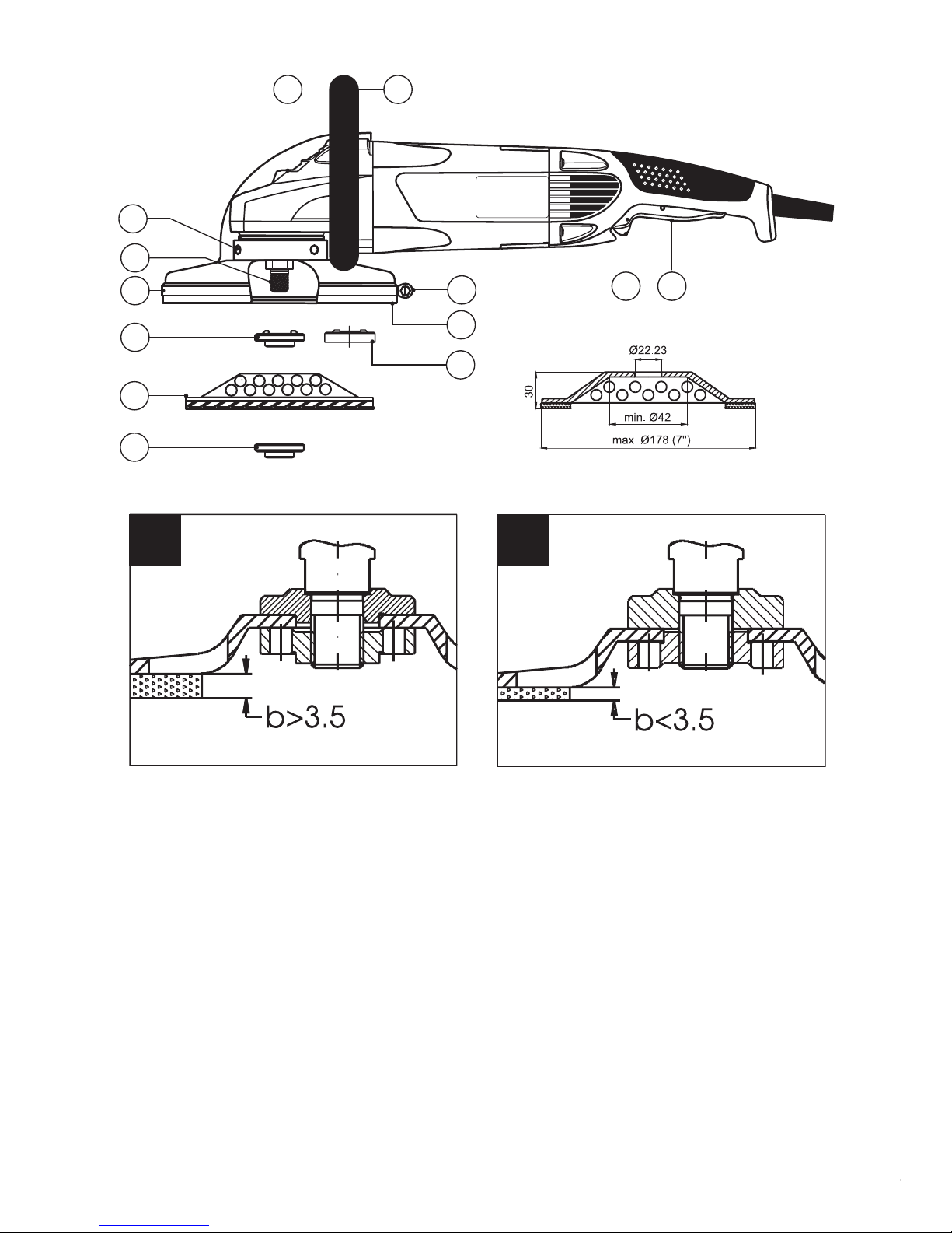
Cup wheel arbor Ø22.23 mm Ø22.23 mm
Cup wheel maximum diameter 178 mm (7”) 178 mm (7”)
New cup wheel maximum thickness 30 mm 30 mm
Dust extraction port diameter Ø35 mm Ø35 mm
Weight (EPTA Procedure 01/2003) 6.9 kg 6.9 kg
Safety class (EN 60745-1) II II
NOISE AND VIBRATION INFORMATION (Measured values determined according to EN 60745.)
Noise emission
A-weighted sound pressure level LpA 91 dB (A) 91 dB (A)
Uncertainty КpA 3 dB 3 dB
A-weighted sound power level LwA 102 dB (A) 102 dB (A)
Uncertainty КwA 3 dB 3 dB
Wear hearing protection!
Vibration emission*
Total vibration values (vector sum in the three axes) determined according to EN 60745:
Grinding concrete
Vibration emission value ah13.5 m/s213.5 m/s2
Uncertainty K 1.5 m/s21.5 m/s2
* The vibration emission values are determined according to 6.2.7 EN 60745-1.
The vibration emission level given in this information sheet has been measured in accordance with a standardised test
given in EN 60745 and may be used to compare one tool with another. It may be used for a preliminary assessment of
exposure.
The declared vibration emission level represents the main applications of the tool. However if the tool is used for
different applications, with different accessories or poorly maintained, the vibration emission may differ. This may
signicantly increase the exposure level over the total working period.
An estimation of the level of exposure to vibration should also take into account the times when the tool is switched
off or when it is running but not actually doing the job. This may signicantly reduce the exposure level over the total
working period.
Maintain the power tool and the accessories and keep your hands warm during operation to reduce the harmful effect
of vibrations.
Dust from material such as paint containing lead, some wood species, minerals and metal may be harmful. Contact
with or inhalation of the dust may cause allergic reactions and/or respiratory diseases to the operator or bystanders.
Certain kinds of dust are classied as carcinogenic such as oak and beech dust especially in conjunction with additives
for wood conditioning (chromate, wood preservative). Material containing asbestos must only be treated by specialists.
▪Where the use of a dust extraction device is possible it shall be used.
▪To achieve a high level of dust collection, use vacuum cleaner for wood or for wood and/or minerals together with
this tool.
▪The work place must be well ventilated.
▪The use of a dust mask of filter class P2 is recommended.
Follow national requirements for the materials you want to work with.
All models are equipped with electronic device for soft start and restriction of starting current to 16 A. Models feature
safety upon mains drop-out. In case of mains drop-out or unplugging for more than 0.5 s the power tool remains
switched off and can be started only after switching off and on the ON/OFF switch. (This safety feature is described in
part “Operation”.)

6
TCG 180L • TCG 180
EN
General power tool
safety warnings
WARNING! Read all safety warnings and
all instructions. Failure to follow the warnings and
instructions may result in electric shock, fire and/or
serious injury.
Save all warnings and instructions for future
reference.
The term “power tool” in the warnings refers to your
mains-operated (corded) power tool or battery-operated
(cordless) power tool.
1. WORK AREA SAFETY
a) Keep work area clean and well lit. Cluttered or
dark areas invite accidents.
b) Do not operate power tools in explosive
atmospheres, such as in the presence of
flammable liquids, gases or dust. Power tools
create sparks which may ignite the dust or fumes.
c) Keep children and bystanders away while
operating a power tool. Distractions can cause
you to lose control.
2. ELECTRICAL SAFETY
a) Power tool plugs must match the outlet. Never
modify the plug in any way. Do not use any
adapter plugs with earthed (grounded) power
tools. Unmodified plugs and matching outlets will
reduce risk of electric shock.
b) Avoid body contact with earthed or grounded
surfaces, such as pipes, radiators, ranges and
refrigerators. There is an increased risk of electric
shock if your body is earthed or grounded.
c) Do not expose power tools to rain or wet
conditions. Water entering a power tool will
increase the risk of electric shock.
d) Do not abuse the cord. Never use the cord for
carrying, pulling or unplugging the power tool.
Keep cord away from heat, oil, sharp edges
or moving parts. Damaged or entangled cords
increase the risk of electric shock.
e) When operating a power tool outdoors, use an
extension cord suitable for outdoor use. Use of
a cord suitable for outdoor use reduces the risk of
electric shock.
f) If operating a power tool in a damp location
is unavoidable, use a residual current device
(RCD) protected supply. Use of an RCD reduces
the risk of electric shock.
3. PERSONAL SAFETY
a) Stay alert, watch what you are doing and
use common sense when operating a power
tool. Do not use a power tool while you are
tired or under the influence of drugs, alcohol
or medication. A moment of inattention while
operating power tools may result in serious
personal injury.
b) Use personal protective equipment. Always
wear eye protection. Protective equipment such
as dust mask, non-skid safety shoes, hard hat, or
hearing protection used for appropriate conditions
will reduce personal injuries.
c) Prevent unintentional starting. Ensure the
switch is in the off-position before connecting
to power source and/or battery pack, picking
up or carrying the tool. Carrying power tools with
your finger on the switch or energising power tools
that have the switch on invites accidents.
d) Remove any adjusting key or wrench before
turning the power tool on. A wrench or a key left
attached to a rotating part of the power tool may
result in personal injury.
e) Do not overreach. Keep proper footing and
balance at all times. This enables better control
of the power tool in unexpected situations.
f) Dress properly. Do not wear loose clothing
or jewellery. Keep your hair, clothing and
gloves away from moving parts. Loose clothes,
jewellery or long hair can be caught in moving
parts.
g) If devices are provided for the connection of
dust extraction and collection facilities, ensure
these are connected and properly used. Use of
dust collection can reduce dust-related hazards.
4. POWER TOOL USE AND CARE
a) Do not force the power tool. Use the correct
power tool for your application. The correct
power tool will do the job better and safer at the
rate for which it was designed.
b) Do not use the power tool if the switch does
not turn it on and off. Any power tool that cannot
be controlled with the switch is dangerous and
must be repaired.
c) Disconnect the plug from the power source
and/or the battery pack from the power tool
before making any adjustments, changing
accessories, or storing power tools. Such
preventive safety measures reduce the risk of
starting the power tool accidentally.
d) Store idle power tools out of the reach of
children and do not allow persons unfamiliar
with the power tool or these instructions
to operate the power tool. Power tools are
dangerous in the hands of untrained users.
e) Maintain power tools. Check for misalignment
or binding of moving parts, breakage of parts
and any other condition that may affect the
power tool’s operation. If damaged, have the
power tool repaired before use. Many accidents
are caused by poorly maintained power tools.
f) Keep cutting tools sharp and clean. Properly
maintained cutting tools with sharp cutting edges
are less likely to bind and are easier to control.
g) Use the power tool, accessories and tool bits
etc. in accordance with these instructions,
taking into account the working conditions
and the work to be performed. Use of the power
tool for operations different from those intended
could result in a hazardous situation.
7
Original instructions
EN
5. SERVICE
a) Have your power tool serviced by a qualified
repair person using only identical replacement
parts. This will ensure that the safety of the power
tool is maintained.
Concrete grinder
safety warnings
WARNING: Before connecting a tool to a power
source be sure that the voltage supply is the same as that
specied on the nameplate of the tool.
▪A power source with a voltage greater than that
specified for the tool can result in serious injury to the
user, as well as damage to the tool.
▪If in doubt, do not plug in the tool.
▪Using a power source with a voltage less than the
nameplate rating is harmful to the motor.
Always wear eye and ear protection
and use a dust mask. The dust and abrasive particles
separated during operation may seriously injure your
health.
▪Hold power tool by insulated gripping surfaces
only, when performing an operation where the
cutting accessory may contact hidden wiring or
its own cord. Cutting accessory contacting a “live”
wire may make exposed metal parts of the power tool
“live” and could give the operator an electric shock.
WARNING: Always switch off and unplug the
power tool prior to any adjustment, servicing or main-
tenance.
▪Never switch on the grinder under load, and leave it
down only after final rotation stop.
▪Always keep the cord away from the working area of
the cup wheel.
▪Fasten the cup wheel only by a special wrench, using
the original base support washer and lock nut.
▪Do not use damaged cup wheels.
WARNING: The grinding accessory continues
rotation even after the machine is switched off.
▪Never apply side pressure to stop the cup wheel
rotation after switching off the grinder.
▪The outer metal parts and the bits may get hot after
continuous operation.
▪Use clamps or a vice to secure your work whenever
possible.
▪Always switch off the machine and wait until the
spindle has come to a complete standstill before
placing it down.
▪Do not force the machine: let the tool do the work at a
reasonable speed. Overloading will occur if too much
pressure is applied and the motor slows resulting in
inefficient work and possible damage to the motor.
▪Rags, cloths, cord, string and the like should never be
left around the work area.
▪Remove any nails, screws, etc. from the processed
surface.
▪Before using the tool on an actual work piece, switch
on and let it run for a while. Operate the tool at least
200 mm away from your face and body.
▪Always be sure you have a firm footing. Be sure no
one is below when using the tool in high locations.
▪Hold the power tool firmly.
▪Keep your hands away from rotating parts. Do not
touch the bit or the work piece immediately after
operation - they may be extremely hot and you may
get serious burns.
▪The tool must be used only for its prescribed purpose.
Any use other than those mentioned in this Manual
will be considered a case of misuse. The user and not
the manufacturer shall be liable for any damage or
injury resulting from such cases of misuse.
▪To use this tool properly, you must observe the
safety regulations, the assembly instructions and
the operating instructions found in this Manual. All
persons who use and service the machine have to
be acquainted with this Manual and must be informed
about its potential hazards. Children and frail people
must not use this tool. Children should be supervised
at all times if they are in the area in which the tool is
being used. It is also imperative that you observe the
accident prevention regulations in force in your area.
The same applies for general rules of occupational
health and safety.
▪The manufacturer shall not be liable for any changes
made to the tool nor for any damage resulting from
such changes.
Even when the tool is used as prescribed it is not
possible to eliminate all residual risk factors. The
following hazards may arise in connection with the tool’s
construction and design:
▪Damage to hearing if effective hearing protection is
not worn.
▪Always unplug the machine prior to any adjustment,
servicing or maintenance including replacing the
accessories.
▪The power tools must not be used outdoors in rainy
weather, or in moist environment (after rain) or in close
vicinity with easily flammable liquids and gases. The
working place should be well lit.
Know your product
Before using the power tool, familiarize yourself with all
the operating features and safety requirements.
Use the tool and accessories only for the applications
intended. All other applications are expressly ruled out.
1. Spindle
2. Wheel guard
3. Support ange
4. Diamond cup wheel
5. Fixing ange
8
TCG 180L • TCG 180
EN
6. Auxiliary handle
7. ON/OFF switch
8. ON/OFF switch locking button
9. Spindle lock button
10. Rubber seal
11. Fastening bracket
12. Flat face support washer
13. Screw
Operation
This power tool is supplied from single-phase alternating
current mains only. It is double insulated according to
EN 60745-1, IEC 60745 and can be connected to
grounded or not grounded sockets. This power tool is
radio suppressed in compliance with EMC Directive
2004/108/EC.
This power tool is designed for rough and ne grinding
concrete and rock material with the purpose of
refurbishing before laying plaster and protective coating.
The machine is designed for dry grinding only.
PRIOR TO INITIAL OPERATION
▪The machine may be delivered with the wheel
mounted at the factory. Ensure that the wheel is
mounted properly and fixed reliably prior to the initial
and any following operation.
▪Make sure the power supply voltage corresponds to
the value indicated on the name plate with technical
data of the tool.
▪Always check the position of ON/OFF switch. The
power tool must be connected to the power supply
socket only when this switch is in OFF position.
▪Make sure that the cord and the plug are in order. If the
replacement of the supply cord is necessary, this has
to be done by the manufacturer or his agent in order
to avoid a safety hazard.
▪Make sure the cup wheel diameter and thick ness do
not exceed the values specified on the name plate.
The maximum number of revolutions indicated on
the cup wheel must not be less that the number of
revolutions of the machine at no load!
WARNING: Always switch off and unplug the
power tool prior to any adjustment, servicing or main-
tenance.
▪Always use the auxiliary handle and hold the machine
firmly with both hands for maximum control over
torque reaction or kickback upon starting.
SWITCHING ON - SWITCHING OFF
The concrete grinder is secured against unintentional
switching on.
▪Switch on: First press the auxiliary button (8)
positioned at the front of ON/OFF switch, then press
ON/OFF switch (7). For continuous operation switch
(7) can be locked. In this case while holding switch (7),
press button (8) and the release switch (7).
▪Switching off: Release switch (7); in case the switch is
locked, first press and then release that switch.
In case of mains drop-out (or temporary drop-out
for time t > 0.5 s), when the ON/OFF switch is in
ON position, the machine should not operate after
supply recovering. To start operating the machine,
rst switch off and then switch on the lever of ON/
OFF switch.
WHEEL GUARD
The wheel guard (2) must always be mounted on the
machine!
ASSEMBLY, REPLACING AND ADJUSTING THE
CUP WHEEL POSITION
Make sure the cup wheel diameter and thickness do not
exceed the values stated in the technical specications.
The maximum admissible speed indicated on the wheel
must not be less than the machine no load speed.
Fix the spindle (1) by pressing the lock button (9) on the
gear case.
WARNING: Never press button (9) while the
spindle is still rotating!
With this button depressed turn the spindle till its
pronounced going deeper. Unscrew lock nut (5) by the
lock nut wrench.
In view of the cup wheel wear and in order to achieve
optimum dust extraction a possibility is provided to adjust
the cup wheel position to the wear of the cup wheel.
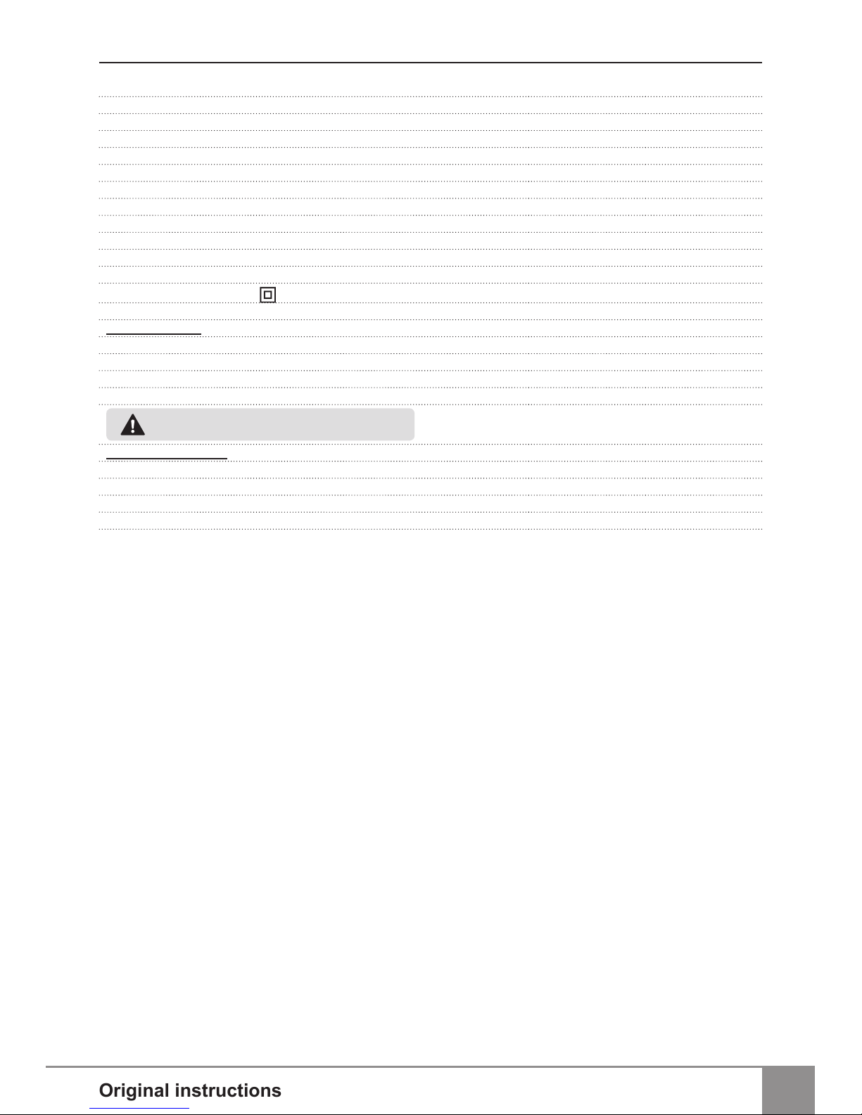
When placing a new cup wheel arrange the components
on the spindle in the following order: base support
washer (3); cup wheel (4); lock nut (5) with its at end
towards the cup wheel as shown on Fig. 1.
WARNING: Placing the lock nut (5) with its
convex end towards the cup wheel shall make tighten-
ing the cup wheel impossible.
In case the cup wheel is half worn out or more, arrange
the components on the spindle in the following order: at
support washer (12); cup wheel (4); lock nut (5) with its
convex end towards the cup wheel as shown on Fig. 2.
WARNING: After replacing the wheel, operate
the machine with the new wheel at no load mode for
minimum 30 seconds. Vibrating or otherwise improp-
erly rotating wheels must be replaced immediately and
discarded.
REPLACING THE BRUSH SHIELD
The rubber seal (10) provides maximum decreasing the
dust emission in the environment. It wears out along with
the wheel. When replacing the wheel, change the rubber
seal as well. Loosen the screw in bracket (11) and remove
the old rubber seal. Place the new seal, taking care the
edge of the wheel guard (2) will enter the provided in the
9
Original instructions
EN
seal groove. Place back the bracket (11) and fasten it.
AUXILIARY HANDLE
The auxiliary handle (6) is fastened to the gear case
through two screws. Always use the auxiliary handle and
hold the machine rmly with both hands.
DUST EXTRACTION
This power tool should only be used with a dust extraction
system. In addition, always wear approved dust mask.
Always make sure the vacuum cleaner that you use is
designed for extraction of masonry dust. Connect the
vacuum cleaner to the dust extraction port on the wheel
guard.
RECOMMENDATIONS
When grinding do not apply pressure to the processed
surface by bearing down on the machine but move the
wheel smoothly. Upon overloading the built-in electronic
protection will actuate and the speed of the wheels will
be reduced considerably.
To resume normal speed draw the machine back from
the processed material. Use the appropriate type of
wheel for the specic operation and the material.
In case the screws (13) loosen they have to be tightened
rmly. Prior to tightening you must lay thread locking
adhesive over each screw thread.
ACCESSORIES TO BE USED
WITH THIS POWER TOOL
▪ Diamond cup wheel Ø178 mm (7’’)
Maintenance
WARNING: Always ensure that the tool is
switched off and unplugged before attempting to per-
form inspection or maintenance.
BRUSH REPLACEMENT
This power tool is equipped with auto-stop brushes.
When the carbon brushes are worn out, the machine
switches itself off. In this case both brushes must be
replaced simultaneously with genuine brushes at
TRELAWNY service centre for warranty and post-
warranty service.
GENERAL INSPECTION
Regularly inspect all fasteners and ensure they are
properly tightened. Should any of the screws be loose,
retighten it immediately to avoid hazards.
In case the screws (13) loosen they have to be tightened
rmly. Prior to tightening you must lay thread locking
adhesive over each screw thread.
Re-lubricate all moving parts at regular intervals.
If the replacement of the supply cord is necessary, this
has to be done by the manufacturer or his agent in order
to avoid a safety hazard.
CLEANING
For safe operation always keep the machine and its
ventilation slots clean.
Regularly check to see if any dust or foreign matter
has entered the grills near the motor and around the
switches. Use a soft brush and/or air jet to remove any
accumulated dust. Wear safety glasses to protect your
eyes whilst cleaning.
Exterior plastic parts may be cleaned with a damp cloth
and mild detergent if necessary.
WARNING: Never use alcohol, petrol or other
cleaning agent. Never use caustic agents to clean
plastic parts.
WARNING: Water must never come into con-
tact with the tool.
IMPORTANT! To assure product safety and reliability,
repairs, maintenance and adjustment (including brush
inspection and replacement) should be performed
by certied service centres or other qualied service
organisations, always using genuine replacement parts.
Notes
Carefully read the entire Original Instructions before
using this product.
The manufacturer reserves the right to make changes
and improvements to the products and to alter
specications without prior notice.
Specications may differ from country to country.

TCG 180L • TCG 180

Pos. No. Ref.No. Description
1540.178878 Gear box
2540.330125 Bearing HK 1212
3540.330944 Bearing 6300 2RSL P63
LDS18SpA
454 0.153 341 Gasket
554 0.173 93 6 Inner Flange
654 0.173 93 4 Circlip
7540.174022 Spindle
8540.173935 Rubber bush
954 0.158247 Bearing bed
10 54 0.11750 4 Spacer washer
11 54 0.11750 5 Spacer washer
12 540.152666 Gear set
13 540.113256 Nut
14 540.174007 Bush
15 540.174021 Spring
16 540.174008 Pin
17 540.330344 O-ring 6X1.5B NBR70
18 540.330352 O-ring 80X2B
19 540.360246 Screw M5x16
20 54 0.175915 Button
21 540.175959 Protective washer
22 540.330473 Circlip А40-1D
23 540.331355 Bearing 6203-2RS (17x40x12)
24 54 0.17593 5 Body
24A 5 40.175910 Body
25 54 0.175911 Brush holder cover
26 540.174004 Diffuser
27 54 0.176 452 Stator set
27A 540.156721 Stator set 110V
28 540.175040 Armature set
28A 540.156722 Armature set 110V
29 54 0.19 002 0 Brush holder set
30 54 0.153 014 Brush
31 540.153015 Brush with a switch
32 540.164934 Rubber bush
TCG 180L • TCG 180
Pos. No. Ref.No. Description
33 540.361360 Screw К 4Х9.5 TORX 20
34 540.361433 Screw 3.9x80
35 540.154350 Fan
36 54 0.1516 48 Protective washer
37 54 0. 331149 Bearing 608-2RS-P63
LDS18SpA
38 54 0.175913 Handle
39 54 0.153 89 4 Switch PS16 E03/RAL9005/
B P 16,5A
39A 5 40.15 3020 Switch 1267
40 540.361328 Screw K4x18 TORX 20
41 540.151671 Cord clamp
42 540.361360 Screw К 4Х9.5 TORX 20
43 540.361371 Screw К5Х40(D10) TORX 20
44 540.120724 Cord protector
45 54 0.152574 Cord with a plug
45A 5 40.16 649 4 Cord with a plug
46 540.361369 Screw A-K 5x25 TORX 20
47 540.152929 Back up disc washer
48 54 0.1218 38 Locking nut
49 540.150015 Special spanner 200
50 540.370399 Spanner 22 DIN 894
51 54 0.1652 38 Handle set
52 540.360791 Washer 2-14
53 540.360790 Bolt D2-M14x20
54 540.361342 Screw M6X6 DIN 914
55 54 0.15825 3 Disk guard
56 54 0.153 037 Bracket
57 540.152722 Gasket 7"
59 540.158254 Disk guard
60 54 0.158248 Bearing bed set
61 54 0.11324 4 Spiral spring
62 540.330331 O-ring 2-10x1,5-2
63 540.330704 O-ring 5x1,5 NBR 70
100a 5 40.1573 64 Electronic block 110V
Parts with “a” prex related to TCG 180L

www.trelawnyspt.co.uk
Email: sales@trelawny.co.uk
Tel: +44 (0)1926 883781
Fax: +44 (0)1926 450352
DECLARATION OF CONFORMITY
We,
Trelawny SPT Limited of
Trelawny House, 13 Highdown Road, Sydenham Industrial Estate, Leamington Spa,
Warwickshire, CV31 1XT, United Kingdom,
Declare that under our sole responsibility for supply/manufacture of the product
Name of product
Part Numbers
Year of production
to which this document related is in conformity with the provisions of the following Directive(s),
Normative Documents and their relevant Standards:
2006/42/EC MACHINERY DIRECTIVE
2004/108/EC DIRECTIVE OF ELECTROMAGNETIC COMPATIBILITY
2011/65/EC RoHS DIRECTIVE
EN 60745-1, EN 55014-1, EN 55014, EN 61000-3-2, EN 61000-3-3
Registered Ofce: Trelawny SPT Ltd, Trelawny House, 13 Highdown Road, Sydenham Industrial Estate, Leamington Spa, Warwickshire, CV31 1XT, United Kingdom
Date and place of issue,
1st January 2014
Leamington Spa, England.
Rob Chapman,
Commercial Director.
DOCUMENT No. Q:57/4
CONCRETE GRINDER
540.2030; 540.2040
2014
This manual suits for next models
3
Table of contents
Other Trelawny Grinder manuals


