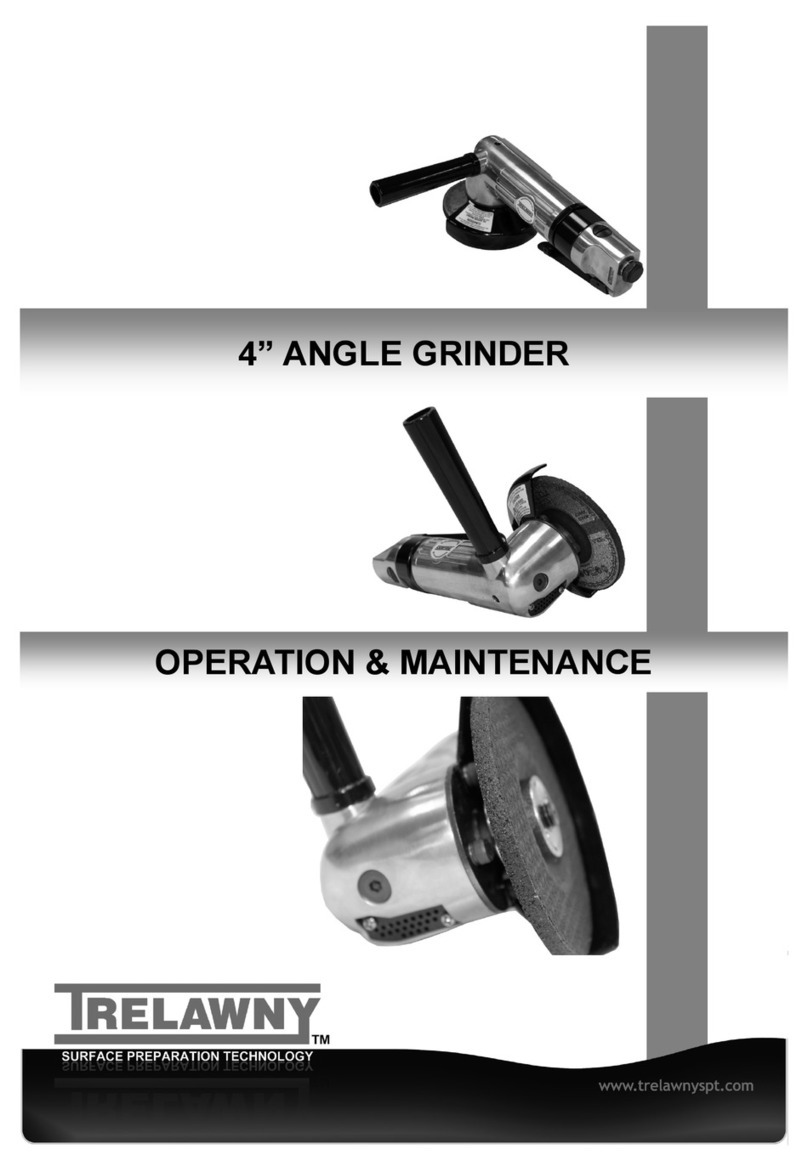
Trelawny 735.7075A User manual

Vibration Reduced 7’’ Angle Grinder
Operation and Maintenance Manual
www.trelawnyspt.co.uk


OPERATION
Foreword
Thank you for your purchase of the
TRELAWNY 7” Angle Grinder
This manual contains the necessary
maintenance information for you to
ensure proper operation and care for
this machine.
It is essential for you to read
through this manual thoroughly.
In the unlikely event that you
experience problems with your Angle
Grinder, please do not hesitate to
contact your local Trelawny dealer or
agent. We always welcome feedback
and comments from our valued
customers.
Safety Precautions
WEAR SAFETY BOOTS, FACE
MASK, SHATTERPROOF GLASSES,
HELMET, GLOVES and any other
personal protective equipment
required for the working conditions.
Avoid loose clothing; this may become
trapped in moving parts and cause
serious injury.
AIR MOTORS ARE NOT
ELECTRICALLY INSULATED.
ENSURE THAT HANDS and clothing
are kept away from rotating parts.
ONLY YOUR SUPERVISOR OR
AUTHORISED MAINTENANCE
ENGINEER should adjust the speed
control setting within the air motor;
although this has been set to the
optimum speed during manufacture,
the speed should be checked on a
daily basis.
ENSURE THAT THE WORK PLACE
IS WELL VENTILATED. Avoid
operating engine-powered
compressors in an enclosed area,
since engine exhaust gases are
poisonous.
BE AWARE, when the angle grinder is
switched off, the work head will
continue to rotate briefly.
The grinder must never be used if a
wheel guard (disc cover) item (53) is
not fitted.
The air supply should be lubricated. It is
strongly recommended that an air filter,
regulator, lubricator is used, this will supply
clean, lubricated air at the correct pressure
to the tool.
Details of such equipment can be obtained
from your supplier.
If such equipment is not used then the tool
should be lubricated by shutting off the air
supply to the tool, depressurising the line
by pressing the trigger on the tool.
Disconnect the air line and pour into the
air intake a teaspoonful (5ml) of a suitable
pneumatic motor lubricating oil preferably
incorporating a rust inhibitor.
Reconnect tool to air supply and run tool
slowly for a few seconds to allow air to
circulate the oil. If the tool is used
frequently lubricate on daily basis and
also if the tool starts to slow or lose power.
Pre-Start Check (Daily)
Check all bolts and screws for tightness.
Ensure that all fittings are secure.
The air motor speed is preset at the
factory to 7,500 rpm (free running).
Always clear the air hose before
connection to the machine.
Ensure that no moisture (condensation)
is present in the air hose.
Check the security of all hoses clamps
and fittings, and that the air pressure is
correct at 90psi (6.3bar).
The air motor uses approximately 7cfm
of air.
The Maximum air pressure is 100psi
(7bar) the air consumption will increase
as the air pressure rises.
It is recommended that the compressor
is capable of supplying at least 20cfm
supply of free air (not displaced, as given
by some compressor manufactures).
This allows for a little “headroom” so the
compressor has some rest periods.
In particularly cold weather it is
recommended that a proprietary anti-
freeze lubricating oil is used.
Risk of Hand-arm
Vibration injury
These tools may cause Hand-arm
Vibration Syndrome injury if their use is
not adequately managed.
We advise you to carry out a risk
assessment and to implement measures
such as; limiting exposure time [i.e.
actual trigger time, not total time at
work], job rotation, ensuring the tools are
used correctly.
Ensure the tools are maintained
according to our recommendations, and
ensuring that the operators wear
personal protective equipment [PPE]
particularly gloves and clothing to
keep them warm and dry.
Employers should consider setting up a
programme of health surveillance to
establish a benchmark for each operator
and to detect any early symptoms of
vibration injury.
We are not aware of any PPE that
provides protection against vibration
injury by attenuating vibration emissions.
See ‘Specifications’ section for vibration
emission data.
Grinding Discs, Flap
Wheels & Applications
Grinding Discs
851.4070 - 7” for use on steel.
Warning:
Do not use Type1, Type 41 and Type 42
cut-off wheels as they can cause serious
injury.
Only use Type 27 grinding wheels with
this tool.
Type 27 wheels are a flat wheel that
have a “depressed centre/raised hub”
some are fitted with a threaded boss,
see special fitting instruction for these in
“Replacing Grinding Discs”.
Use of tool
This right angle grinder is designed to be
used with reinforced resin bonded
depressed centre grinding wheels that
have a permitted rotational speed in
excess of 7,500 RPM.
The tool is designed to be used for
grinding and dressing of welds, etc. but
not for cutting off.

SAFETY RULES
Safety Rules for a Grinder
1. Read all the instructions before using this tool. All operators must be fully trained in its use and be aware of these
safety rules.
2. Do not exceed the maximum working air pressure.
3. Use personal protective safety equipment.
4. If the tool appears to malfunction remove from use immediately and arrange for service and repair.
5. If the tool is used with a balancer or other support device ensure that it is fixed securely.
6. Always keep hands away from the working attachment fitted to the tool.
7. The tool is not electrically insulated. Never use the tool if there is any chance of it coming into contact with a live
electrical source.
8. Always when using the tool adopt a firm footing and/or position and grip the tool firmly to be able to counteract any
forces or reaction forces that may be generated whilst using the tool.
9. Use only correct spare parts. Do not improvise or make temporary repairs.
10. Do not lock, tape, wire, etc. the on/off valve in the run position. The trigger/lever etc. must always be free to return to
the ‘off’ position when it is released.
11. Always shut off the air supply to the tool, and depress the trigger/lever to release air from the feed hose before fitting,
adjusting or removing the working attachment.
12. Check hose and fittings regularly for wear, replace if necessary. Do not carry the tool by its hose and ensure the hand
is remote from the on/off control when carrying the tool with the air supply connected.
13. Take care against entanglement of moving parts of the tool with clothing, ties, hair, cleaning rags, etc. This will cause
the body to be drawn towards the tool and can be very dangerous.
14. Users will adopt safe working practices and observe all relevant legal requirements when installing, using or
maintaining the tool.
15. Do not install the tool unless an easily accessible and easily operable on/off valve is incorporated in the air supply.
16. Take care that the tool exhaust air does not cause a problem or blows on another person.
17. Never lay a tool down unless the working attachment has stopped moving.
18. A grinding wheel should only be fitted by a competent person trained to do so. The wheel must be of the correct size
and speed rating.
19. Check the speed of the grinder at least once per week, if it is in regular use, with an accurate tachometer.
20. The tool must only be used with the grinding wheels as set out in section “Use of the Tool” and shown on parts list.
Carry out the instructions as set out in “Putting into Service”.
21. Many countries have local or national rules re the use and fitting of grinding wheels. Make sure such rules are
observed.
22. Use a barrier to prevent sparks causing a hazard to the operator, any other person or anything within the vicinity of the
sparks.
23. If a wheel guard becomes damaged or has withstood a wheel breakage, the guard must be changed.
24. Do not use chipped or cracked grinding wheels.
25. Always wear impact resistant eye protection.
26. Use only the disc plates, Items (65) and (66) provided with the grinder for locating and clamping the wheel. Never use
substitutes. Use the paper blotter fixed to the wheel as this ensures even tightness when the wheel is secured.
27. Tighten the wheel plates sufficiently to prevent wheel spin off when the grinder is turned off. Do not tighten excessively
as this may crack the wheel.
28. The noise from the tool or the process noise of the grinding operation may be such that hearing protection should be
worn.
29. Avoid inhaling dust from the grinding process. Wearing of a breathing mask is recommended. Grinder certain materials
may mean that special breathing precautions are necessary. Seek advice before using the tool.
30. Always ensure that the work piece is firmly supported so that it cannot move during the grinding process.
31. If the grinder is dropped do not use unless the wheel is first checked for damage by a competent person.
32. When not in use the grinder should be stored in a safe place where it will not be damaged. If a tool has not been used
for a period of time check the tool as for the first time of using.
33. Be aware that if the grinding process causes high vibration, special precautions should be taken.
34. The operator should be aware that the grinding wheel will continue to rotate after the power supply has been shut off.
This could cause a hazard.
35. Always store grinding wheels in accordance with the manufacturer’s instructions.
36. 38) Check frequently that the spindle thread has not become damaged or worn.
37. 39) Always ensure that the grinding wheel has a higher permissible running speed to the speed of the grinder.

OPERATION
Putting into service
Remove plastic bung from air inlet using
a pair of pliers.
Use a clean lubricated air supply that will
give a measured air pressure to the tool
of 6.3bar (90psi). It is recommended a
air filter/regulator/lubricator is used which
can be obtained from air tool supplier.
Operating
With the grinder correctly connected to
the air supply, check the speed of the
grinder with an inlet pressure of 100
psi/7.0 bar measured at the tool inlet.
Check with a calibrated tachometer.
Check that the guard (53) is in position
and securely fixed.
Unsure that the grinding wheel is of the
correct dimensions, that it is not cracked
or chipped and has a permitted speed
rating higher than the maximum
permissible running speed of the grinder
which is 7,500 RPM.
When first starting the grinder with a new
or changed wheel fitted, the grinder
should first be started in a protected area,
i.e. such as under a heavy bench well
away from other persons and run for, say,
one minute.
This will provide protection if the wheel
should break because of a fault that was
not visibly detected
Always use eye protection and wear
protective gloves if there are sharp edges
in the working area.
Disconnect tool from air supply.
To dismantle, insert the peg spanner (63)
into disc nut (65/66) and with a spanner
(56) on the flats of gear shaft (51)
unscrew disc nut, take off disc and
unscrew disc receiver (64).
Check that it is screwed tightly to the shaft
and locates the bore of the grinding wheel
on the spigot of the disc receiver and
screw on disc nut item (65/66) using the
spanners provided. It should be tight
enough to prevent wheel spin off when
the air supply is shut off.
If you intend using the alternative
threaded hub grinding wheels with this
tool, the following procedure must be
followed.
1) Remove the rear, wheel mounting
flange (64). (65,66 & 67 not required)
2) Screw on the threaded Disc with the
hexagon boss at the rear face of the
wheel.
3) Hold the spindle with the spanner
provided and securely tighten the
wheel with a second wrench.
Only use threaded hub wheels certified
by the disc manufacturer
Handle the grinder with care.
If the grinder is dropped, carefully
examine the wheel for damage and
replace if necessary.
Start the machine as if for the first time of
fitting a wheel, i.e. under a bench.
Make sure the object to be ground is in a
firm fixed position.
The tool and the grinding process can
create a noise level such that ear
protectors should be worn.
If the grinding process creates a dust then
use a suitable breathing mask.
Check that the material being worked will
not cause harmful dust or fumes. If this is
so then special breathing apparatus may
be required. Seek advice before starting
work.
If the grinder vibrates when first fitting the
wheel or during use, remove from service
immediately and arrange for the fault to
be corrected before continuing to use.
Do not apply excessive pressure as this
will reduce the cutting efficiency.
Apply light loads and allow the wheel to
cut.
Replacement Grinding
Disc Instructions
Only personnel trained in the Abrasive
Wheels Regulations 1970 standard for the
correct fitting of grinding wheels must
maintain this tool.
PUWER 98, which covers the selection
and use of work equipment in general,
revoked the remaining provisions of the
Abrasive Wheels Regulations 1970
(these dealt with the training,
competence and appointment of people
to mount abrasive wheels).
See also ANSI B7.1 Safety code for the
use, care and protection of abrasive
wheels.This tool has an output shaft with
5/8-11 UNC threaded shaft.

EXPLODED VIEW
Ref Part No Description
1 370.987001 Regulator
2-1 370.90B-02 O’Ring
2-2 370.9288303 O’Ring
3 370.987003-2 Inlet Bushing (BSP)
370.987003 Inlet Bushing (NPT)
4 370.987004 Protecting Rubber
5 370.987005 Clamp Nut
6 370.987006 Washer
7 370.987007 Spring
8 370.987008 Valve
9 370.987009 Washer
10 370.90B-04 O’Ring
11 370.9288306 Valve Stem
12 370.90B-03 Snap Ring
13 370.987013 Housing
17 370.980509 Lever
18 370.912012.1 Pin
19 370.987019 Washer
20 370.987020 Spring Holder
21 370.987021 Washer
22 370.987022 Spring
23 370.987023 Governor
24 370.987024 Pin
25 370.987025 Governor Weight
26 370.987026 Governor Pin
27 370.987027 Governor Cage
Ref Part No Description
28 370.987028 Washer
29 370.987029 Bearing x 2
30 370.987030 Rear Plate
31 370.987031 Rotor Blade x 4
32 370.987032 Rotor
33 370.981326 Pin x 2
34 370.987034 Cylinder
35 370.987035 Front Plate
36 370.987036 Bearing
37 370.987037 Bevel Gear (13T)
38 370.987038 Silencer
39 370.987039 Angle Housing
40 370.9870011 O’Ring x 2
41 370.987041 Silencer x 2
42 370.987042 Exhaust Sleeve x 2
43 370.987043A Screw
44 370.987044 Handle
45 370.987045 Spacer
46 370.987046 Bearing
47 370.987047 Retaining Ring
48 370.987048 Bevel Gear (20T)
49 370.987049 Bearing
50 370.987050 Key
51 370.987051A-1 Shaft (U/K Version)
370.987051A Shaft (US Version)
52 370.987052 Face Plate
Ref Part No Description
53 370.987053 Disc cover (7”)
54 370.9870403 Screw x 6
55 370.987054 Screw
56 370.987056 Stop Spanner (19mm)
57 370.988045 Stop Spanner (25mm)
58 370.987058 Snap Ring
59 370.987059 Stainless Mesh x 2
60 370.987060 Hex (6mm)
61 370.9ST87056 Nut
63 370.987057.1 Disc Spanner
64 370.988041A Face Plate
65 370.988042.1 Disc Nut
66 370.988043 Disc Nut
67 370.988044 Screw
68 370.960929 Hex (5mm)
69 370.921029 Oil Cup

TECHNICAL SPECIFICATIONS
Trelawny tools are thoroughly tested under specified conditions in accordance with applicable internationally recognised standards.
When a tool is used on site the conditions may not be the same as those used in our tests
Trelawny Surface Preparation Technology operates a policy of continuous product development and refinement and therefore
reserves the right to change technical specifications and product designs without giving prior notice.
© Copyright 2015, Trelawny SPT Limited, CV31 1XT. UK All rights reserved. Any unauthorised use or copying of the contents or part
thereof is prohibited. This applies to trademarks, model denominations, part numbers and drawings.
Use only genuine Trelawny spares.
The use of non-Trelawny spare parts invalidates the warranty.
Description 7” Air
Weight 3.1kg/6.8lbs
Spindle dia 5/8” -11 UNC
Length 318mm (12.5”)
Air consumption 7cfm@90psi (3/8””BSP inlet)
Maximum air pressure 7 bar (100psi)
No load RPM 7,500 RPM
Motor Power - HP 1.7hp
Motor Power - kW 1.25kW
Air exhaust Side , adjustable angle
Recommended hose bore - to a max length 10 metres 10mm (3/8”)
Vibration (AEQ)
Primary hand position (trigger position) <2.5 m/s2 (k)
Test method in accordance with ISO standards BS EN ISO 28927-5:2009
Noise
Noise LpA (Pressure Level) BS EN ISO 15744:2008 90 dB(A)
This tool meets the requirements of the following Standards:
BS EN ISO 11148-7:2012 Hand-held non-electric power tools. Safety requirements. Grinders
Noise level measured in accordance with EN ISO 15744: 2008
Vibration measured in accordance with: EN ISO 28927-5:2009
NOTE: The above vibration levels were obtained from tri-axial measurements to comply with the requirements of “The Control of
Vibration at Work Regulations 2005*” and to EN ISO 28927 and EN ISO 20643 series of standards. These values are at least 1.4
times larger than the values obtained from single axis measurements.
(K) Equals the factor of uncertainty, which allows for variations in measurement and production.
Vibration data figures are tri-axial, which gives total vibration emission.
Actual real world testing on a steel surface can give readings of approximately 11.5m/s2 (k)

NOTES

NOTES

NOTES

Trelawny SPT Ltd
13 Highdown Road, Sydenham Industrial Estate, Leamington Spa,
Warwickshire, CV31 1XT, United Kingdom
Telephone: +44 (0)1926 883781 - Fax: +44 (0)1926 450352
Email: [email protected]
© TSPT UK 2013 Part No: 735.7072 issue 17.11.16 www.trelawnyspt.co.uk
Table of contents
Other Trelawny Grinder manuals
