N.KO PASOVEC 75 RUNNER User manual

1
MOBILE BELT GRINDER
PASOVEC 75 RUNNER
Purchase order No. 1300 – 400 V / 60 Hz
Purchase order No. 13001 – 480 V / 60 Hz
Purchase order No. 13002 – 220 V / 60 Hz
Operating manual
CHANGE RESERVED

2
Contents:
General information 3
Description of RUNNER machine 3
Identification data 4
Tests 4
Warranties 4
Safety regulations 5
Technical specification 7
Accessories 7
Device unpacking 7
Controls of RUNNER 8
Use 9
Maintenance and operation 10
Spare parts 11
List of spare parts 12
Wiring diagram 14
Basic dimensions 15
Always read the operating instructions carefully before use

3
1. General information
Thank you for purchasing one of our machines and we hope you will be fully satisfied
with it.
This manual contains all the instructions for installing, adjusting, operating and
maintaining the PASOVEC 75 RUNNER in accordance with applicable safety
standards.
The information and data in this manual may be subject to change as a
result of further machine upgrading. To resolve any doubts, please contact
N.KO Machines in case of discrepancies.
Never perform any operations on the machine before you read and understand the
instructions in the manual. Lots of accidents that occur at the workplace are caused
by not following the guidelines and recommendations contained in the manual.
Graphical symbols in this manual are used to highlight important information about
the safety and operation of the machine.
Attention:
Important information for the operator's personal safety.
Important:
Instruction to be followed to ensure the proper operation of the machine.
2. Description of the PASOVEC 75 RUNNER machine
The mobile belt grinder PASOVEC 75 RUNNER only is designed for the
following activities:
The mobile belt grinder PASOVEC 75 RUNNER is designed for grinding at a workshop
or a production hall.
This is a hand-driven machine. Only use the machine in an environment protected
from rain, snow and other adverse weather conditions.
Mobile belt grinder PASOVEC 75 RUNNER - Mobile sander PASOVEC 75
RUNNER – the special belt grinder developed for flat grinding applications.
Particularly for grinding of the welds in the material surface and further for removal
of the undesirable layer resulting from the rolling of metal sheets or after metal
sheet cutting by means of plasma or oxygen.
The machine has a stable chassis, a quick adjustment mechanism and a depth stop
for precise grinding depth adjustment.

4
• Continuous grinding depth adjustment
• System for the quick working mode deactivation
• The workplace of flat grinding of small workpieces
• Low operating costs
Purchase order No.
1300 – 400 V / 60 Hz
13001 – 480 V / 60 Hz
13002 – 220 V / 60 Hz
3. Identification data
The identification data of the PASOVEC 75 RUNNER mobile grinder are listed on the
label attached to the machine body.
4. Tests
The PASOVEC 75 RUNNER mobile grinder is tested in our technical testing room.
During this test the correct function of the machine is tested.
5. Warranties
The seller provides for the PASOVEC 75 RUNNER mobile belt grinder the warranty
that the goods will be free of any material and manufacturing defects for the period
of 12 months from the date of the goods delivery.
The warranty of the perfect operation of the goods and the used materials is 12
months from the date of the goods delivery.
The seller undertakes to remove any defects covered by the warranty free of charge
and without undue delay so that the buyer can properly use the goods. If the buyer
applies the rights of liability for defects not covered by the warranty, he shall pay to
the seller any costs associated with the warranty.

5
The manufacturer considers the warranty invalid in the case of:
• machine misuse.
• use contrary to national or international standards
• incorrect installation
• faulty power supply
• serious maintenance deficiencies
• unauthorized modifications or interventions
• Using other than original and factory-approved spare parts and accessories for
the model in question
• Complete or partial non-compliance with the instructions in this manual
• exceptional events, natural calamities, or others.
6. Safety regulations
Attention:
To avoid injury, observe the following
Before starting work make sure the machine is not mechanically or otherwise
damaged.
Only operate the machine if the power cord is not damaged. Regularly
check the condition of the machine and the supply cable. In the event of
damage, have it replaced immediately by a workshop authorized to carry out such
repairs. Contact your supplier.
The employer is obliged to inform operators about safety standards and make sure
that they are complied with. Make sure the work space is large enough and well lit.
"Operator" means a person who installs, operates, adjusts, maintains, cleans and
repairs the machine.
Attention:
Prior to work commencing the operator must become familiar with
the machine's features and must read this entire manual.
Attention:
When working with the machine, take increased care and wear safety aids for safe
work.

6
Operator (s) must always:
1. Make sure before the machine starts that all safety covers are mounted and
that the safety devices are functional.
2. Avoid wearing the type of clothing or jewellery that might be caught in
moving parts.
3. Wear approved safety clothing, such as footwear with non-slip sole, hearing
protectors, and safety goggles.
4. Apply safety standards, see that they are always upheld, and in case of any
doubts, look again in this manual before taking any action.
5. Contact the machine supplier if the defects that cause the machine to
malfunction cannot be remedied when the defects relate to faulty parts or
irregularities.
Safety device
The machine is equipped with an emergency button. It is red, and stops the
machine immediately before all other operations.
This emergency button is used:
• To turn off the machine
• In case of immediate danger or mechanical accident
Remaining risks
The machine has been designed and manufactured with all the equipment and
equipment to ensure the health and safety of the operator.
The machine is designed in such a way that the risk of contact with movable
parts is as low as possible.

7
7. Technical specification
PASOVEC 75 RUNNER
Voltage (V)
400 V (220 V, 480 V)
Frequency (Hz)
60 Hz
Motor(kW)
3 Kw
Belt speed (m/s)
30 m/s
Size of grinding belt (mm)
75X2000 mm
Weight (kg)
70 kg
W x H x L (mm)
610x944x1419 mm
8. Accessories
Purchase order No. BELT STANDARD ZK75X2000
Universal grinding belt 75x2000mm, grain optional 36, 60, 80 or 120 (package of 10
pcs)
Purchase order No. PAS top Quality XK75X2000
TOP Quality grinding belt is designed for grinding stainless steel 75x2000mm,
optional grain 36, 60, 80 or 120 (package of 10 pcs)
9. Device unpacking
Unpack the machine from a wooden box and check that everything is OK and the
machine is undamaged. If you have any questions, please contact your reseller.
Mobile belt grinder PASOVEC 75 RUNNER is supplied:
Belt grinder PASOVEC 75 RUNNER
Packed in the wooden box
1 pc of the grinding belt, grain 80
Operation manual

8
10. Controls of the mobile belt grinder PASOVEC 75
RUNNER
1. Securing the machine in the non-working position (transport
mode)
2. Power supply connection and ON/OFF control
3. Emergency switch
4. Belt centering mechanism
5. Removal adjustment mechanism

9
11. Use
Always unplug the power supply before adjusting the machine.
1. Release the mechanism lever to secure the machine in the transport position
(pos. 1)
2. Using the removal adjustment mechanism (pos.5), ensure that the contact
wheel with the abrasive belt is slightly touching the material. Set the removal
mechanism adjustment before using the machine to the position so that it has
sufficient power for subsequent removal adjustment.
3. Re-secure the machine lock lever in the transport position (pos.1)
4. Connect the appliance to the power supply (pos. 2). Before connecting to the
power supply (pos. 2), always make sure that the device is not damaged.
5. Press the green button to start the device
6. Set the desired removal depth. Hold the device behind the control handle to
prevent the machine from starting spontaneously. Start with the less removal
and gradually increase the value until the machining depth matches your
requirement or working with the machine is still comfortable.
7. Hold the control handle firmly and press the machine in front of you to start
the grinding process.
8. Adjust the size of the removal as required, see point number 2.
9. When finished, turn the appliance off with the red button and disconnect it
from the power supply.
Attention:
When adjusting, use gloves and other personal protective equipment. The
operations must be performed on the machine at rest and after
disconnection from the power supply.
10
12. Maintenance and operation
Pay attention to the maintenance of the drive and contact wheel. Monitor their wear
and weighing. Remove dirt. Regularly clean and maintain the cleanness of the
outside of the grinder and remove the shredded material and dust from the outlet
and the inside of the grinder.
Important:
Pay the increased attention to the wear of the graphite pad on the flat
grinding surface. In case of its wear, excessive friction occurs and
overloading and consequent damage to the machine may occur.
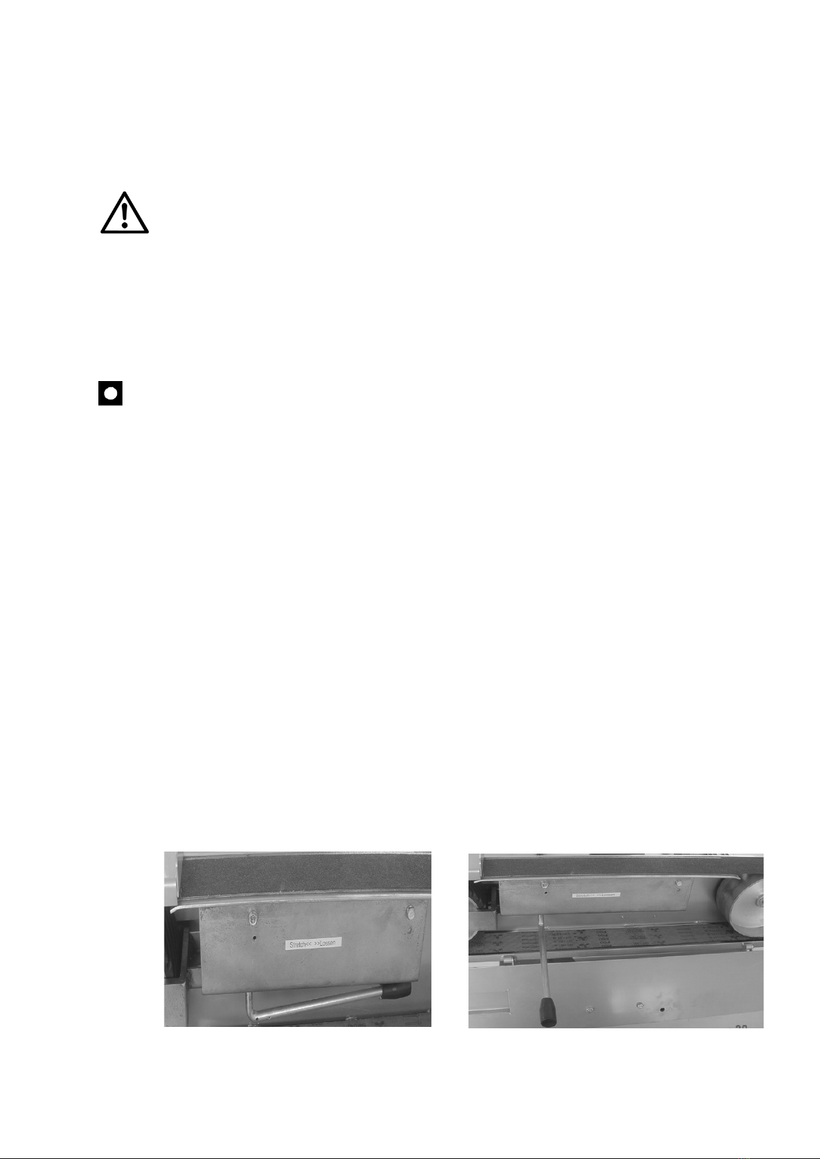
Belt replacement
We only can achieve satisfactory grinding results when using a completely clean
grinding belt. Otherwise, the belt must be replaced.
This can be done by unlocking the handle of the eccentric mechanism that tensions
the belt. After removing the grinding belt and replacing it with the new one return
the eccentric handle to its original position.
Proceed as follows:
- Switch off the machine.
- Make sure that the belt is completely at rest.
- Use the Allen key to open the side cover.
- Loosen the belt using the belt tension lever.
- Replace the belt.
- Check the condition of the graphite pad on the flat grinding surface
- Tension the belt using the belt tension lever.
- Close and secure the side cover.
- Before starting maintenance, disconnect the power supply from the socket
first. Adjustment, lubrication and maintenance must be carried out when the
machine is completely at rest.

11
13. Spare parts and accessories
Purchase orders for spare parts must contain the following information:
• Machine type
• Serial number
• Description of the required part and its number
• Quantity
13.1 List of spare parts

12
PART
NO.
DESCRIPTION
QTY
Art. Nr.
PART
NO.
DESCRIPTION
QTY
Art. Nr.
1
SUPPORT
ASSEMBLY
1
1300_1
46
SUPPORTING
PLATE
1
1300_46
2
JOYSTICK
1
1300_2
47
BLACK LEAD
PLATE
1
307518/1
3
FIFTH WHEEL
1
1300_3
48
BEIVEN WHEEL
GUIDE
1
1300_48
4
HANDLE
1
1300_4
49
HANDLE
1
1300_49
5
HANGER
BEARING
1
1300_5
50
TAPER KNOB
1
1300_50
6
WHEEL
2
1300_6
51
SPRING
1
1300_51
7
WHEEL AXLE
1
1300_7
52
TENSION SPRING
2
1300_52
8
PULL RING
2
1300_8
53
SPRING
1
1300_53
9
REGULATING
PLATE
2
1300_9
54
HANDWHEEL
1
BS75X2000_22
10
MECANUMWHEEL
2
1300_10
55
WEDGE LOCK
1
BS75X2000_21
11
DISTANCE
SLEEVE
2
1300_11
56
DRIVEN GEAR
1
BS75X2000_11
12
GOBE
1
1300_12
57
ABRASIVE BAND
1
1300_57
13
MAIN SWITCH
1
1300_13
58
DRIVING WHEEL
1
BS75X2000_59
14
JUNCTION BOX
1
1300_14
59
HANDLE
CONNECTING
ROD
1
1300_59
15
HANDWHEEL
1
1300_15
60
BIANMENMEN
COVER
1
1300_60
16
FIXED PIPE
1
1300_16
61
LOCATING BUSH
2
1300_61
17
LIFTING PIPE
1
1300_17
62
PLATE
1
1300_62
18
SCREW M12
1
1300_18
63
HANDLE
1
1300_63
19
FIXED CASTER
1
1300_19
64
HINGE
4
1300_64
20
HANDLE
1
1300_20
65
GEARSHIFT
LEVER KNOB
1
1300_65
21
HEXAGON
HEADED BOLT
M10X120
1
1300_21
66
PATTERN
HANDLE
2
1300_66
22
WASHER Φ10
1
1300_22
67
HOLE CHECK
RING
2
1300_67
23
LOCKNUT M10
1
1300_23
68
WHEEL AXLE
1
1300_68
24
WASHER Φ14
6
1300_24
69
HINGE PIN
1
1300_69
25
NUT M14
4
1300_25
70
HEXAGON
SOCKET
COUNTERSUNK
HEAD
SCREWM8X16
4
1300_70
26
SCREW M6X50
1
1300_26
71
HEXAGON HEAD.
BOLT M8X12
2
1300_71

13
27
LOCKNUT M6
1
1300_27
72
HEXAGON
HEADED BOLT
M8X25
4
1300_72
28
SCREW M4X8
2
1300_28
73
HEXAGON
HEADED BOLT
M8X20
3
1300_73
29
WASHER Φ4
2
1300_29
74
BUTTON HEAD
SCREW M8X20
2
1300_74
30
NUT M4
2
1300_30
75
NUT M8
4
1300_75
31
SCREW M6X10
4
1300_31
76
BUTTON HEAD
SCREW M4X6
16
1300_76
32
HEXAGON
HEADED BOLT
M8X12
4
1300_32
77
INNER HEXAGON
SCREW M6X20
1
1300_77
33
WAD
16
1300_33
78
HEXAGON
HEADED BOLT
M6X14
1
1300_78
34
HEXAGON
HEADED BOLT
M8X30
4
1300_34
79
WASHER Φ35XΦ
8X3
1
1300_79
35
LOCKNUT M12
2
1300_35
80
SPRING WASHER
Φ8
9
1300_80
36
LOCKNUT M8
2
1300_36
81
COTTER PIN Φ
3X20
1
1300_81
37
HEXAGON
HEADED BOLT
M8X20
9
1300_37
82
INNER HEXAGON
SCREW M5X20
1
1300_82
38
SCREW
6
1300_38
83
DEEP GROOVE
BALL BEARINGS
6204
2
1300_83
39
THRUST
BEARING 51101
2
1300_39
84
WASHER Φ6
1
1300_84
40
HINGE
2
1300_40
85
NUT M6
2
1300_85
41
ELECTRIC
MACHINE
1
1300_41
86
LOCKNUT M6
1
1300_86
42
FUSELAGE
1
1300_42
87
43
WICKET DOOR
1
1300_43
88
44
TOP TABLE
1
1300_44
89
45
U -SUPPORT
1
1300_45
90
14
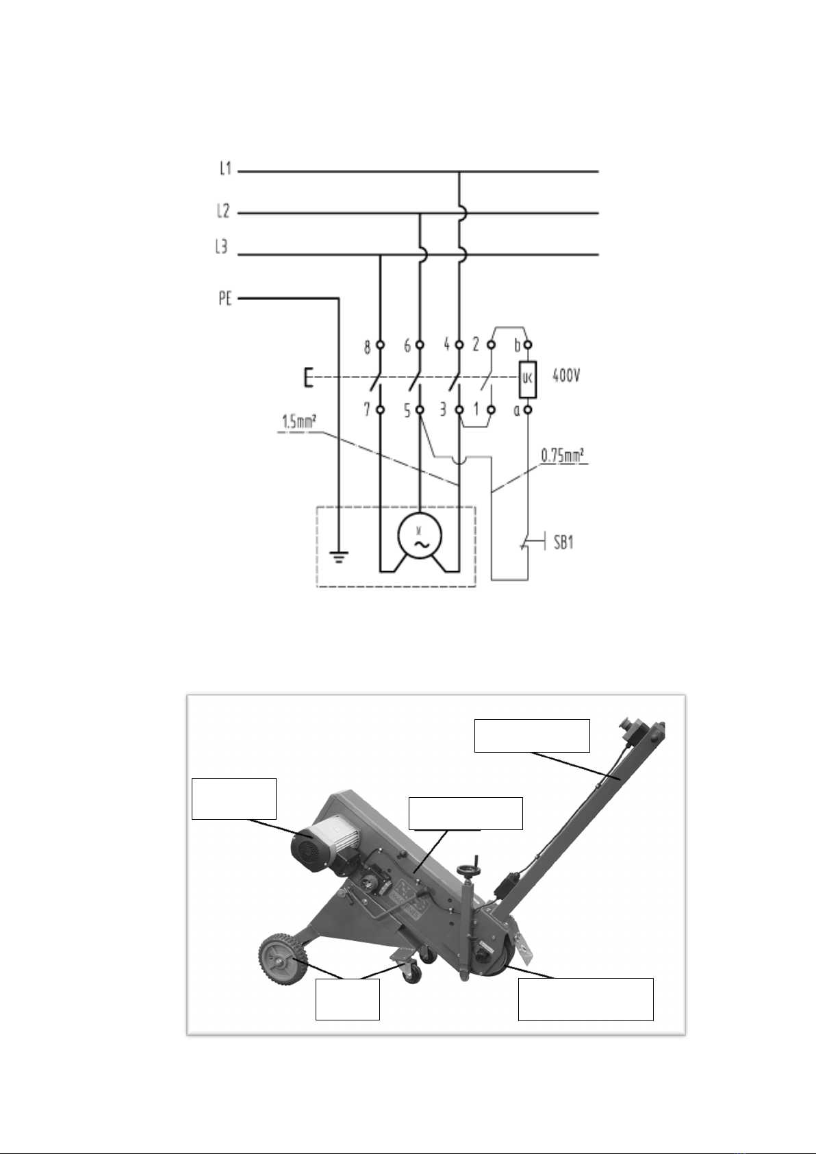
13.2 Wiring diagram
13.3 Basic dimensions and parts of the PASOVEC 75 RUNNER
mobile belt grinder
Control handle
Grinder body
Contact wheel
travel
Engine

15
A copy of this manual comes with each RUNNER machine.
All rights reserved.
No part of this publication may be reproduced without the prior consent of N.KO
N.KO spol. s r.o.
Táborská 398/22
293 01 Mladá Boleslav
The Czech Republic
phone: +420 326 772 001
BEVELER USA INC.
a Member of Richtr Group
producer of bevelling machines
328 14th Street
Ambridge, PA 15003
6538 Collins Avenue, #286
Miami Beach, FL 33141
Table of contents


 operating instructions")


