trendpoint ENKAPSIS User manual

Enkapsis & EnerSure Platform
Installation Guide

Enkapsis & EnerSure Platform Installation Guide Rev07.2
2
Danger!!!
The electrical components of this system
may contain voltage and /or amperage
sufficient to injure or kill. Installation is only
to be performed by a licensed, bonded and
qualified electrician. All installations and
use of this product are the sole
responsibility and liability of the purchaser.
This Installation Guide is valid for the following
firmware:
-
System Firmware 0.12.0+
-
3 Phase Meter Firmware 1.18.0+

Enkapsis & EnerSure Platform Installation Guide Rev07.2
3
Contents
ENKAPSIS® ......................................................................................... 5
The Enkapsis® PQM Overview................................................................................................. 5
Component Description.......................................................................................................... 6
Current Transformers ......................................................................................................... 6
Common Current Transformers .......................................................................................... 7
Power Supply...................................................................................................................... 8
Hardware Installation and Wiring ........................................................................................... 9
Electrical Wiring Instructions 3- Phase................................................................................. 9
RS-485 Wiring ................................................................................................................... 13
EnerSure BCPM 2.0 ................................................................................ 16
Overview.............................................................................................................................. 16
BCPM 2.0.............................................................................................................................. 17
Current Transformers ........................................................................................................... 17
Common Current Transformers ........................................................................................ 19
EnerSure iBCPM..................................................................................... 20
Overview.............................................................................................................................. 20
iBCPM CT Strips .................................................................................................................... 21
Figure 9: iBCPM CT Strip.......................................................................................
21
Setting Strip Jumpers ........................................................................................................ 24
Current Transformers ........................................................................................................... 25
Common Current Transformer Dimensions....................................................................... 26
iBCPM CT Strip Bracket Dimensions ...................................................................................... 27
CT Strip Addressing Diagram................................................................................................. 28
iBCPM System Block Diagram ............................................................................................... 29
EnerSure iBCPM2.0................................................................................ 30
Overview.............................................................................................................................. 30
iBCPM PCBs.......................................................................................................................... 31
Figure 15: iBCPM2.0 PCB ......................................................................................
31
Address Selection ............................................................................................................. 32
Setting Phase Selector .......................................................................................................... 35
Current Transformer Installation .......................................................................................... 36

Enkapsis & EnerSure Platform Installation Guide Rev07.2
4
EnerSure Bus........................................................................................... 37
EnerSure Bus Overview......................................................................................................... 37
Current Transformers ........................................................................................................... 38
Current Transformer Dimensions ...................................................................................... 39
Installation ........................................................................................................................... 40
CT Wiring and Jumper Positioning......................................................................................... 45
Wiring Connectors ............................................................................................................ 45
Setting Board Jumpers...................................................................................................... 46
Address Matrix ..................................................................................................................... 49
EnerSure Bus2.0...................................................................................... 50
Bus2.0 Overview................................................................................................................... 50
Current Transformer Installation .......................................................................................... 51
Bus2.0 CT Installation ........................................................................................................... 52
CT Wiring and Jumper Positioning......................................................................................... 56
Wiring Connectors ............................................................................................................ 56
Setting Phase Selector ...................................................................................................... 57
Address Matrix ..................................................................................................................... 57
Startup and Use ................................................................................ 59
Initial Startup........................................................................................................................ 59
Assigning IP Address............................................................................................................. 60
Using the Web Interface....................................................................................................... 61
Circuit Configuration............................................................................................................. 62
Sampling Live Data with Web Interface................................................................................. 63
Power Scaling ....................................................................................................................... 64
Firmware Update Procedure................................................................................................. 64
Waveform Capture............................................................................................................... 65
Enkapsis & EnerSure Platform Installation Guide Rev07.2
5
ENKAPSIS®
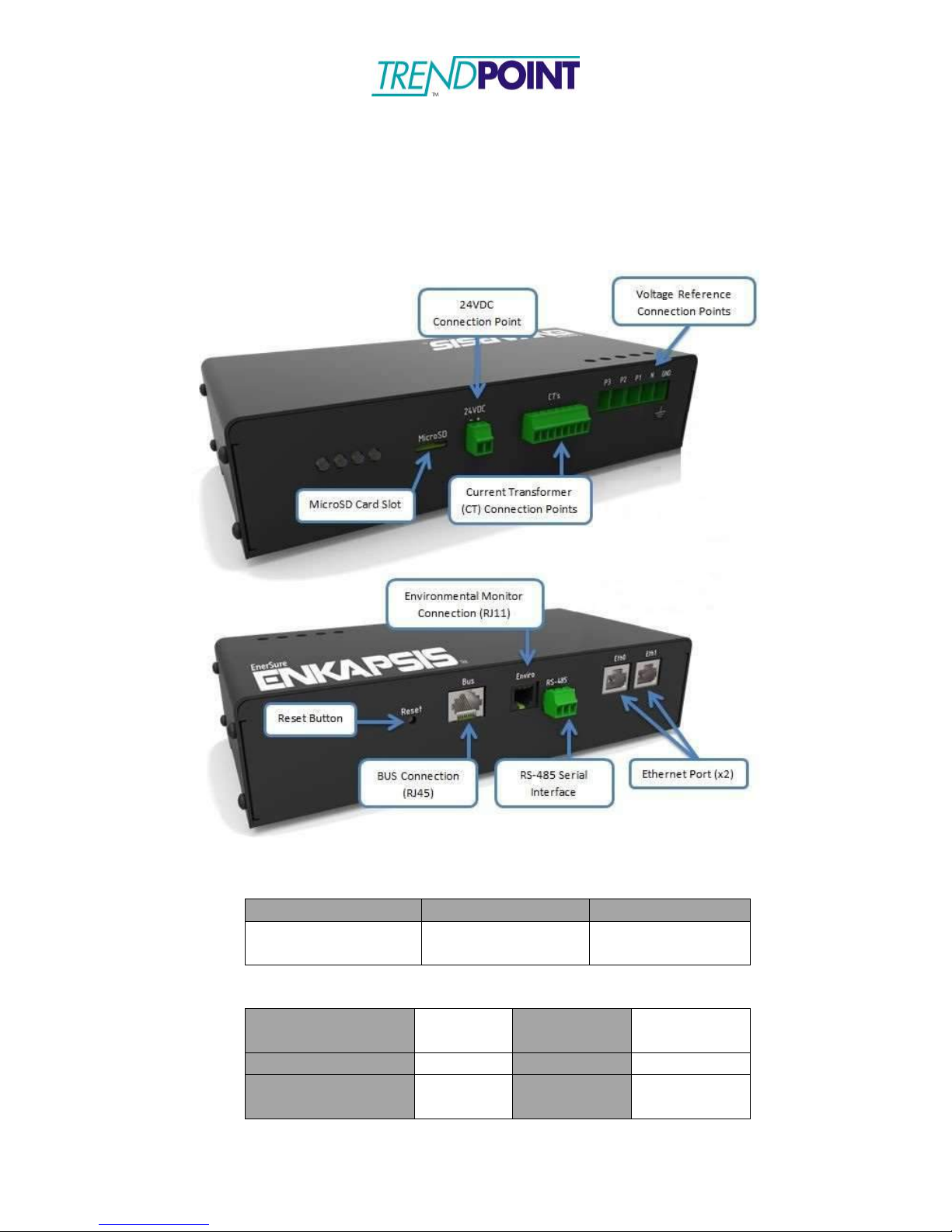
The Enkapsis® PQM Overview
The Enkapsis PQM system is comprised of the PQM, Current Transformers (CT),
and the Power Supply. The EnerSure provides true RMS data for Volts, Amps,
Power Factor, Watts, kWh, kVAR, kVARh, Hz, vTHD and iTHD.
Figure 1: Enkapsis PQM
Dimensions
Length
Width
Height
8.90 in
226.00 mm
4.15 in
105.41 mm
2.10 in
53.34 mm
Electrical Properties
Current Accuracy
±0.5%
Volts In
24VDC
120-277VAC
Power Accuracy
±0.5%
Amps (Max)
250mA
Operating
Temperature
32°-100°F
0°-38°C
Frequency
50-60HZ

Enkapsis & EnerSure Platform Installation Guide Rev07.2
6
Component Description
Current Transformers
Each Current Transformer (CT) can be connected to a circuit by opening or
removing the top of the CT and snapping it onto the wire going from the power
source to the load. THE CT LABEL ALWAYS FACES THE POWER SOURCE.
Be sure to close the CT tightly or it will affect the readings your Enkapsis PQM
provides. Refer to Figure 2 to reference pictures of our most commonly used
CT’s.
Note: We currently offer a variety of CT’s capable of monitoring
current loads ranging from 0 to 5000 amps.
The CT’s may be simply hung on the wire which they snap around. However,
some customers may prefer to use Velcro strips on the bottom or hinged side of
the unit, to allow for ease of mounting and removal when necessary. Velcro is
non-conductive and should not bring any code issues into play.
The white and black lead wires from each CT are associated with specific ports
on the Enkapsis PQM.
Each CT output has two wires. In North America, ALWAYS CONNECT THE
WHITE WIRE FROM EACH CT TO THE CONNECTOR PORT CLOSEST TO
THE VOLTAGE REFERENCE INPUT AND CONNECT THE BLACK WIRE TO
THE SECOND CT INPUT. ALSO BE SURE TO KEEP THE PAIRED LEAD
WIRES TOGETHER. MIXING LEAD WIRES WILL RESULT IN LOSS OF DATA
AND POSSIBLE DAMAGE TO THEUNITS.
Enkapsis & EnerSure Platform Installation Guide Rev07.2
7
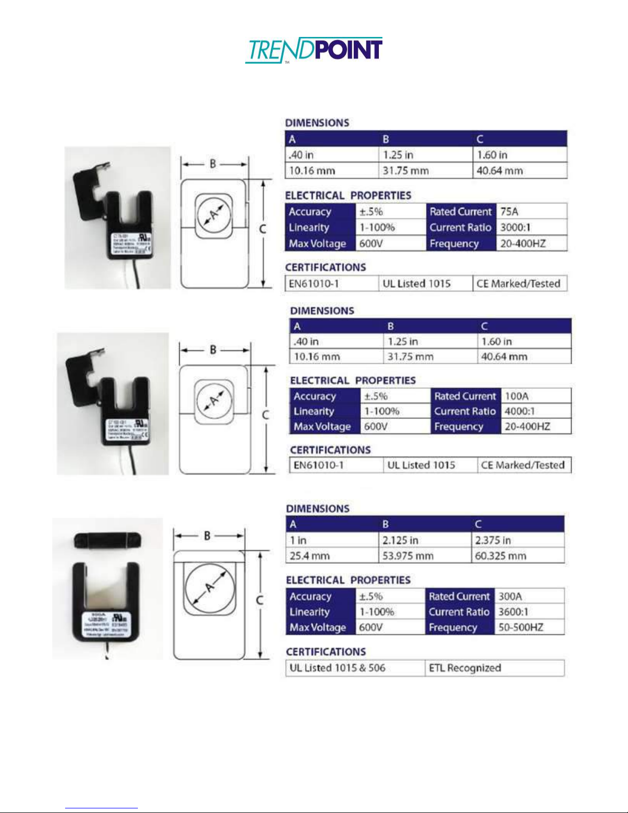
Common Current Transformers
Figure 2: Commonly Used CT’s
Enkapsis & EnerSure Platform Installation Guide Rev07.2
8
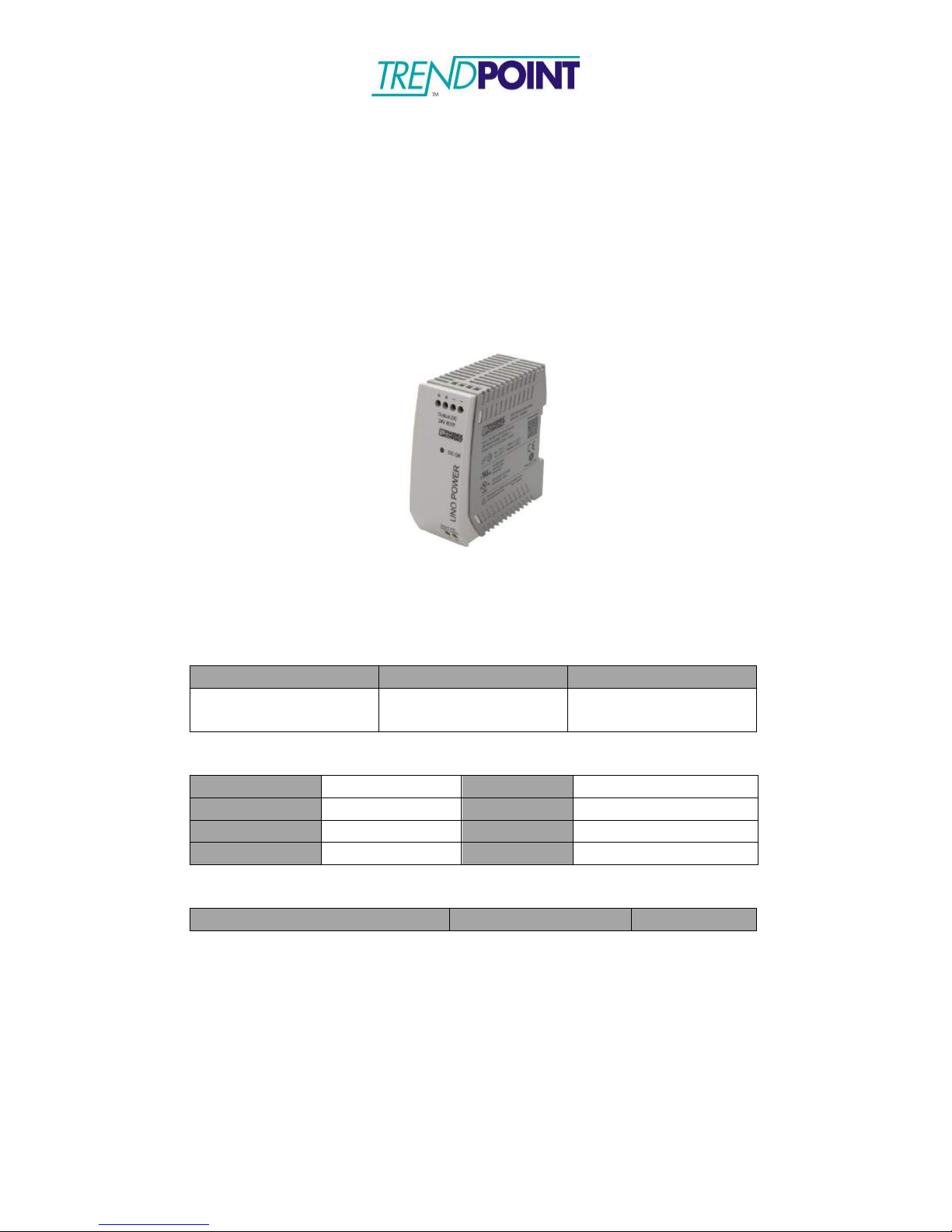
Power Supply
The power supply for the Enkapsis PQM is a Phoenix Contact precision power
supply. This unit requires a 120/240VAC 50 or 60hz input.
The power supply provides 24 volts DC power via one positive and one negative
output terminal. There is no ground output terminal. At 24 volts, the Ekapsis unit
uses approximately 25 mA – 250 mA of power depending on the connected
EnerSure device (BCPM 2.0, iBCPM, Bus, Display).
Figure 3: 24VDC 60W Power Supply
Dimensions
Length
Width
Height
3.31 in
84 mm
1.38 in
35 mm
3.54 in
90.00 mm
Electrical Properties
Nom. Volts In
100-240V
Volts Out
24VDC ±1%
Max Volts In
85-264V
Amps Out
2.5A
Max Amps In
2A
Pwr Out
60W
Frequency
45-65HZ
Certifications
EN61010-1, 61000-3-3 , 50082
CE Marked/Tested
UL 508, 1310
Enkapsis & EnerSure Platform Installation Guide Rev07.2
9
Hardware Installation and Wiring
Electrical Wiring Instructions 3- Phase
Your Enkapsis PQM has 3 separate electrical components that you will need to
connect in order to use the system- Voltage Reference, Power Supply, and
Current Transformers.
All wiring terminals on the Enkapsis PQM can support copper wiring 24-12AWG.
The terminal screws should be tightened to 4.5 lb – inch of torque.
1)
Connect the 24VDC output from the Power Supply to the 2 terminal input
on the Enkapsis.
2)
Connect the 120/208 OR 277/480 VAC input, depending on your system
being monitored, to the Power Supply.
3)
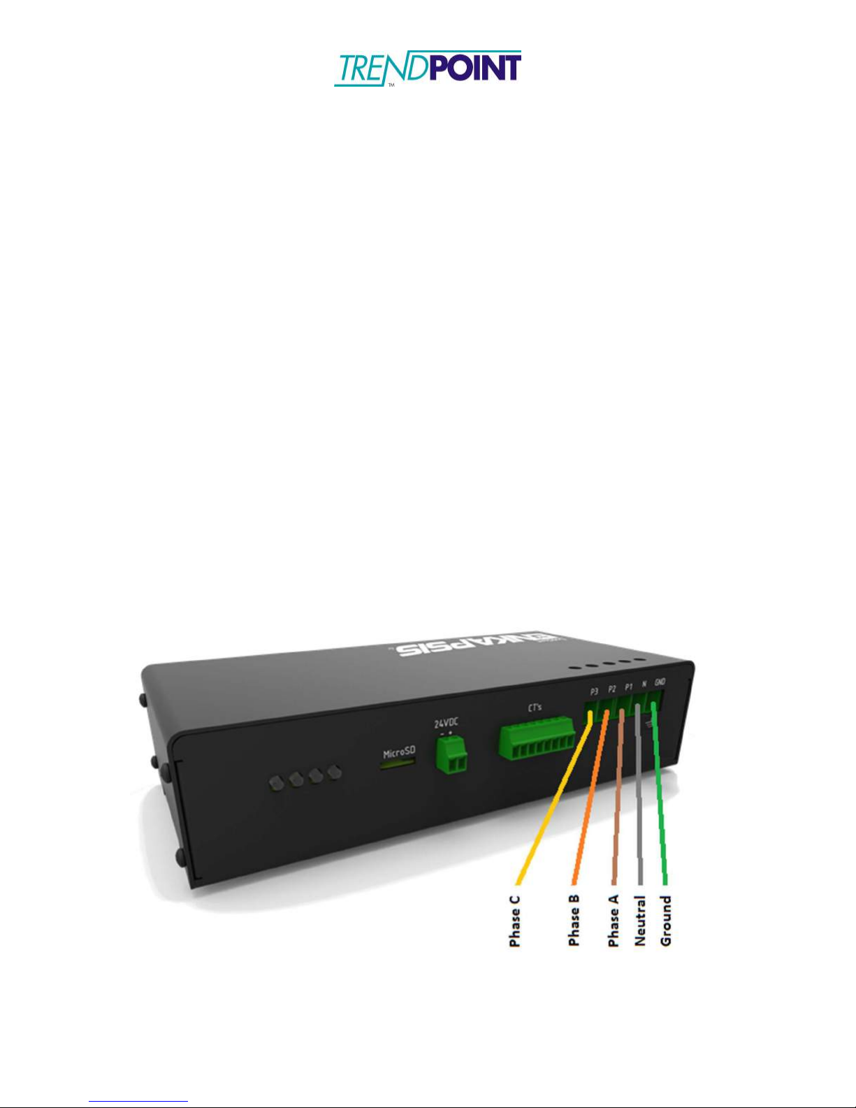
The Enkapsis meter supports the measurement of all of the following
types of voltage (The connection requirements are shown below as well):
a. Three Phase Wye Power (Also known as 5 wire with Phase A,
Phase B, Phase C, Neutral and Ground - Also See Figure 4 for an
example):
i.
Connect the three phases to a 3-Phase Common-Trip
Breaker of no greater that 15A overcurrent protection located
near the Enkapsis meter (UL listed for Voltages up to 480V
RMS).
ii.
Connect the outputs of the 3-Phase Common-Trip Breaker
to the Voltage Reference connection points on the Enkapsis
meter as shown in the picture below.

Enkapsis & EnerSure Platform Installation Guide Rev07.2
10
b. Three Phase Delta Power (Also known as 4 wire with Phase A,
Phase B, Phase C, and Ground – Also See Figure 5 for an
example):
i.
Connect the three phases to a 3-Phase Common-Trip
Breaker of no greater that 15A overcurrent protection located
near the Enkapsis meter (UL listed for Voltages up to 480V
RMS).
ii.
Connect the outputs of the 3-Phase Common-Trip Breaker to
the Voltage Reference connection points on the Enkapsis
meter as shown in the picture below. Note that the B Phase
connection is to be connected to the space normally used for
the Neutral Connection for the Wye Three Phase scheme.
*Note: If installing in IT-S power distribution, a 4-conductor disconnect
MUST be used (3-phase + neutral).
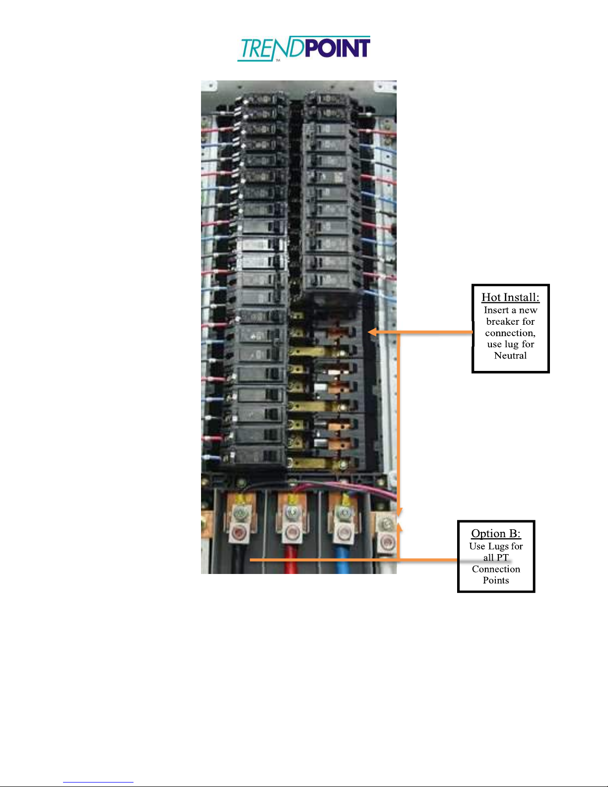
4)
Connect the Current Transformers(CT’s).
a.
CT’s should be run from the power panel that is being monitored to
the Enkapsis PQM.
b. The CT’s should be installed with the label facing the source of
power.
c. The wires connected to the Enkapsis PQM terminals should be
installed in a White/ Black configuration, with the white wire of each
CT closest to the Voltage Reference Input, and should be tightened
to 3 lb – inch torque.
d. The CT wires may be cut to length.
5)
Ensure all wiring connections are secure. Once all wiring has been
confirmed energize the Power Supply input.

Enkapsis & EnerSure Platform Installation Guide Rev07.2
11
THE GROUND CONNECTION TO THE ENKAPSIS PQM IS MADE DIRECTLY
FROM A STABLE GROUND CONNECTION ON YOUR POWER PANEL. THE
GROUND CONNECTION DIRECTLY TO THE ENKAPSIS IS ABSOLUTELY
MANDATORY AND USE WITHOUT THIS GROUND WILL VOID YOUR
WARRANTY AND CREATE A SAFETY HAZZARD.
THE GROUND CONNECTION TO THE ENKAPSIS PQM IS MADE DIRECTLY
FROM A STABLE GROUND CONNECTION ON YOUR POWER PANEL. THE
GROUND CONNECTION DIRECTLY TO THE ENKAPSIS IS ABSOLUTELY
MANDATORY AND USE WITHOUT THIS GROUND WILL VOID YOUR
WARRANTY AND CREATE A SAFETY HAZZARD.
Figure 4: Wiring Diagram for 120/208VAC Three Phase Wye Configuration

Enkapsis & EnerSure Platform Installation Guide Rev07.2
12
THE GROUND CONNECTION TO THE ENKAPSIS PQM IS MADE DIRECTLY
FROM A STABLE GROUND CONNECTION ON YOUR POWER PANEL. THE
GROUND CONNECTION DIRECTLY TO THE ENKAPSIS IS ABSOLUTELY
MANDATORY AND USE WITHOUT THIS GROUND WILL VOID YOUR
WARRANTY AND CREATE A SAFETY HAZZARD.
Figure 5: Wiring Diagram for 480VAC Three Phase Delta Configuration
Enkapsis & EnerSure Platform Installation Guide Rev07.2
13
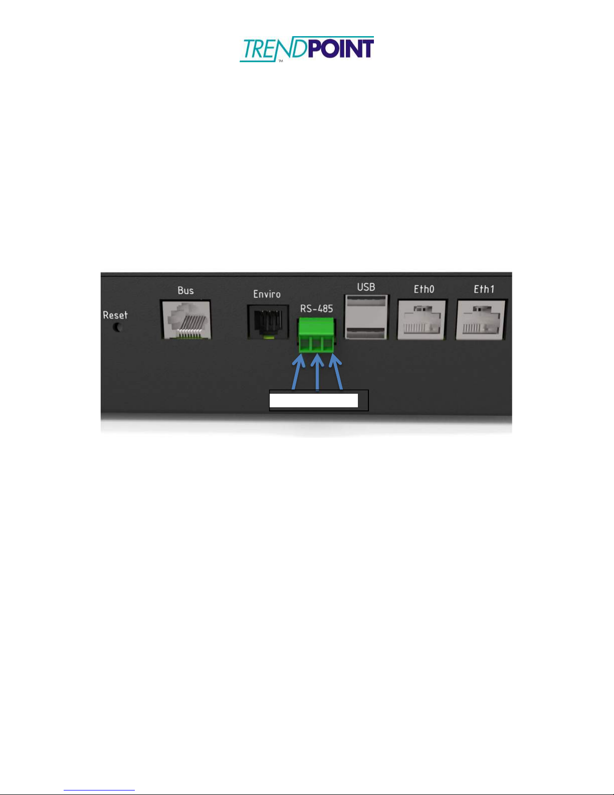
RS-485Wiring
The Enkapsis PQM supports RS-485 Modbus RTU communications. To facilitate
RS-485 communications the following connections should be made. The
EnerSure device can support a multi-drop network on RS-485 2wire.
1)
Connect the communications wire to the 3- pin terminal block.
D+ / D- / GND
Figure 6: RS-485 Wiring
D+ D- GND
Enkapsis & EnerSure Platform Installation Guide Rev07.2
14
Figure 7: Connection Points for Voltage Reference

Enkapsis & EnerSure Platform Installation Guide Rev07.2
15
Figure 8: Close-up of CT Connection Points (300A CT Shown)
Enkapsis & EnerSure Platform Installation Guide Rev07.2
16
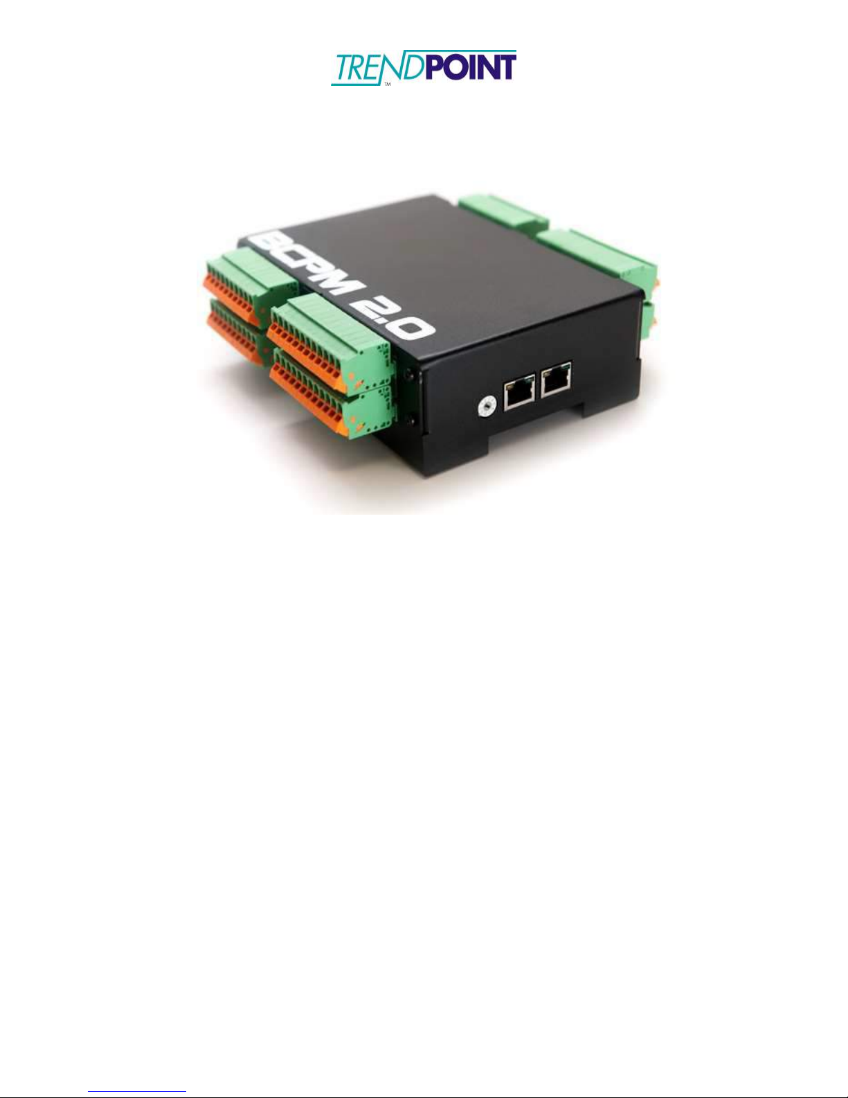
EnerSure BCPM 2.0
Overview
The EnerSure BCPM 2.0 system consists of three (3) main components:
1.) Enkapsis PQM
2.) EnerSure BCPM 2.0
a.
Installed in the enclosure for the Enkapsis and connected to Enkapsis via a
straight-through CAT5/CAT6 cable.
b.
Comes in 2 sizes: a 24 circuit and 42 circuit modules. Two 42
circuit modules can be combined into a single housing to produce a
84 circuit module.
3.) Current Transformers
a.
The CTs provided with the system are split core and are attached to the
circuit after a wire has been connected to the breaker.
b.
Standard CT’s come with 12ft leads which can be cut to properly fit the
installation.
Enkapsis & EnerSure Platform Installation Guide Rev07.2
17
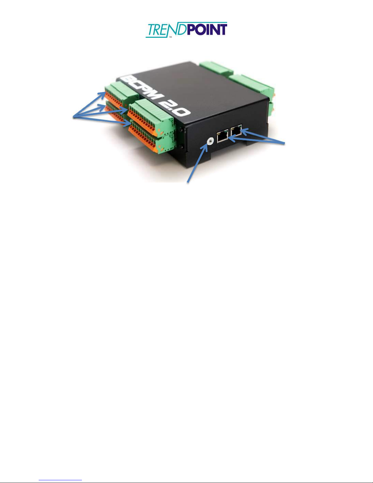
CT Connectors
RJ-45 Connectors
Addressing Switch
BCPM 2.0
The BCPM 2.0 should be mounted inside an enclosure or panel in close proximity to the
Enkapsis unit. The BCPM 2.0 received its power, voltage reference, and communications
via a straight-through CAT5/CAT6 cable that is connected to one of the BCPM 2.0’s RJ-
45 connectors and the BUS port on the Enkapsis.
Note: Multiple BCPM 2.0s can be daisy chained together, via RJ-45 connectors, to allow
monitoring of up to 120 circuits.
Current Transformers
Each Current Transformer (CT) can be connected to a circuit by opening or
removing the top of the CT and snapping it onto the wire going from the power
source to the load. THE CT LABEL ALWAYS* FACES THE POWER SOURCE.
Be sure to close the CT tightly or it will affect the readings your EnerSure unit
provides. Refer to Figures 5 and 6 to reference pictures of our most commonly
used CT’s.
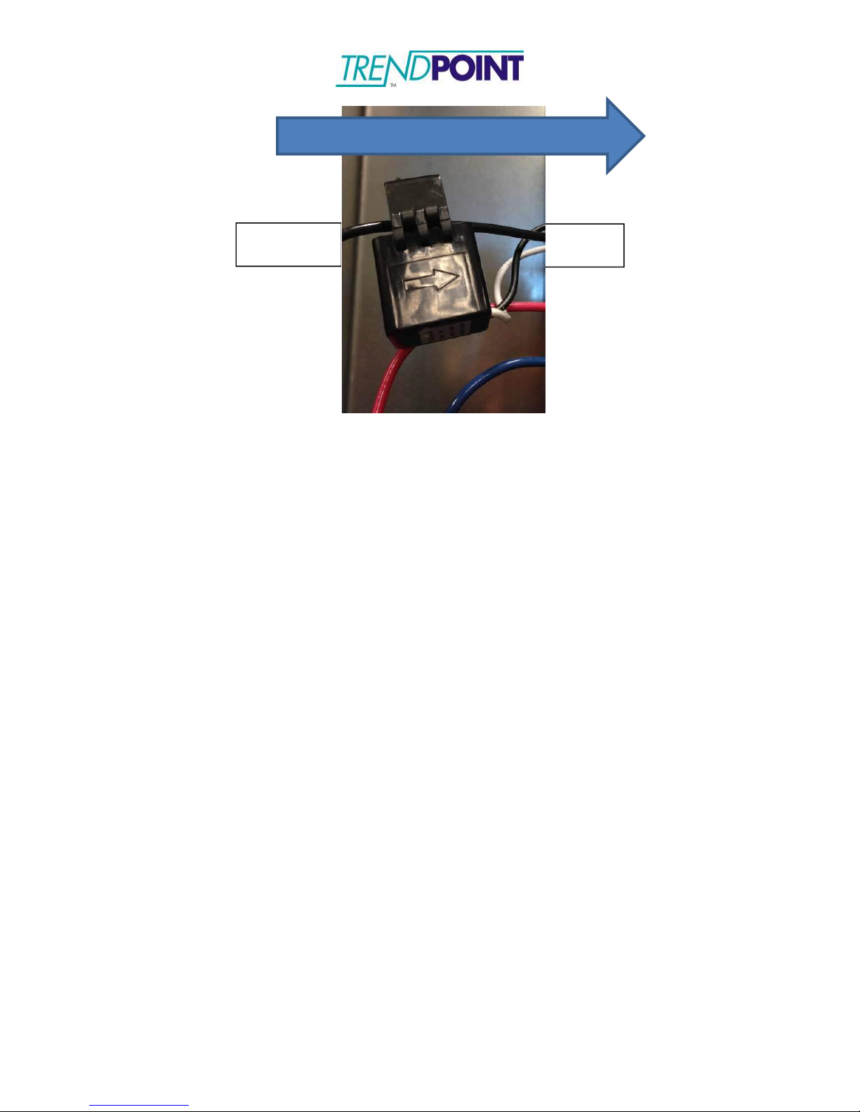
*Note: We currently offer a variety of CT’s capable of monitoring current
loads ranging from 0 to 5000 amps. Specific 75A CT’s, marked with an
arrow, should be oriented using the directional arrow, not the label, see
below figure.
Enkapsis & EnerSure Platform Installation Guide Rev07.2
18
The CT’s may be simply hung on the wire which they snap around. However,
some customers may prefer to use Velcro strips on the bottom or hinged side of
the unit, to allow for ease of mounting and removal when necessary. Velcro is
non-conductive and should not bring any code issues into play.
The white and black lead wires from each CT are associated with specific ports
on the BCPM 2.0. Note that the numbered positions on your breaker panel will
correspond to the numbered positions on your BCPM 2.0 as follows:
Breaker Panel Circuit Number
BCPM 2.0 Connector Level
BCPM 2.0 Connector Position
1-22
1 (Bottom)
1-22
23-44
2
1-22
45-66
3
1-22
67-84
4 (Top)
1-18
Each CT output has two wires. In North America, ALWAYS CONNECT THE
WHITE WIRE FROM EACH CT TO THE CONNECTOR PORT CLOSEST TO
THE RJ-45 CONNECTOR AND CONNECT THE BLACK WIRE TO THE
SECOND CT INPUT. ALSO, BE SURE TO KEEP THE PAIRED LEAD WIRES
TOGETHER. MIXING LEAD WIRES WILL RESULT IN LOSS OF DATA AND
POSSIBLE DAMAGE TO THE UNITS.
An example of connecting the CT’s would be connecting circuit number 1 on your
breaker panel to the bottom connector, terminal 1. Circuit number 23 is
connected to the second level connector, terminal 1. Circuit number 84 is
connected to the top connector, terminal 18. The odd numbered circuits on the
BCPM 2.0 are located on the left hand side of the board just as the odd
numbered circuits on the power panel are located on the left-hand side and even
numbers circuits located on the right hand side.
Current Flow
Breaker
Load
Enkapsis & EnerSure Platform Installation Guide Rev07.2
19
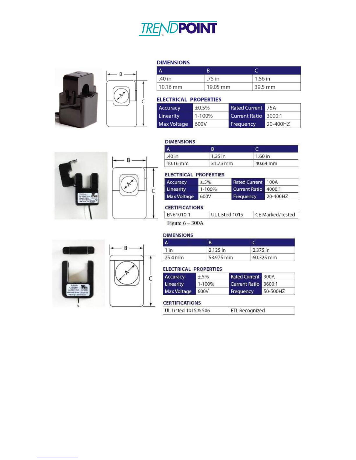
Common Current Transformers

Enkapsis & EnerSure Platform Installation Guide Rev07.2
20
EnerSure iBCPM
Overview
The EnerSure iBCPM system consists of three (3) main components:
1.) Enkapsis PQM
2.) EnerSure iBCPM CT Strips
a.
Installed in the panel that is being monitored by the system. The CT strips
are mounted next to the breakers and are design for panels with ¾”
breaker spacing.
b.
The current transformers plug into the CT strip.
c.
Each CT strip supports 21 current transformers.
3.) Current Transformers
a.
The CTs provided with the system are split core and are attached to the
circuit after the wire has been connected to the breaker.
b.
The standard CT size is 75A and is designed to be fit into panels with ¾”
breaker spacing.
Table of contents


