Treo Fitness G102 User manual

HOME GYM OWNER’S MANUAL
FOR MODEL :
G102

Introduction
Important Precautions
Before You Begin
Assembly Instructions
Conditioning Guidelines
Troubleshooting
Maintenance
Limited Home-use warranty
3
4
5
9
20
24
25
26
CONGRATULATIONS and THANK YOU for your purchase of this Treo home gym!
Whether your goal is to tone your muscles, increase your strength or simply enjoy a fuller, healthier
lifestyle, a Treo home gym can help you attain it – adding club-quality performance to your at-home
workouts, with the ergonomics and innovative features you need to get stronger, healthier and faster.
We’re committed to designing fitness equipment from the inside out, so we use only the highest quality
components. It’s a commitment we back with one of the strongest warranty packages in the industry.
You want exercise equipment that offers the most comfort, the best reliability and the highest quality in its
class. A Treo home gym delivers!
INTRODUCTION
TABLE OF CONTENTS
3
SAVE THESE INSTRUCTIONS
Read all instructions before using this Treo Home Gym. It is the responsibility of the owner to ensure that
all users of this Home Gym are adequately informed of all warnings and precautions.
•
Close supervision is necessary when this home gym is used by, on, or near children or disable persons.
•
Use this appliance (or home gym) only for its intended use as described in this manual. Do not
use attachments not recommended by the manufacturer.
•
Never drop or insert any object into any opening.
•
If you experience any kind of pain, including but not limited to chest pains, nausea, dizziness,
or shortness of breath, stop exercising immediately and consult your physician before continuing.
•
Do not wear clothes that might catch on any part of the home gym.Always wear athletic shoes
while using this equipment.Do not jump on the home gym.
•
At no time should more than one person be on home gym while it is in operation.
•
The home gym should not be used by persons weighing more than 120 kg (264 lbs).
Failure to comply will void the warranty.
•
The home gym is intended for in-home use only. Do not use this home gym in any commercial,
rental, school or institutional setting. Failure to comply will void the warranty.
•
Do not use outdoors.
•
Always stand on the foot plate when performing an exercise that could cause the Treo home gym to tip.
•
Keep the Treo home gym indoors, away from moisture and dust. Place the Treo home gym on a
level surface, with a mat beneath it to protect the floor or carpet. Make sure that there is enough
clearance around the Treo home gym to mount, dismount, and use the Treo home gym.
•
Keep hands and feet away from moving parts.
•
Make sure that the cables remain on the pulleys at all times. If the cables bind while you are
exercising, stop immediately and make sure that the cables are on all of the pulleys.
IMPORTANT PRECAUTONS
FOR HOUSEHOLD USE ONLY
TO REDUCE THE RISK OF INJURY TO PERSONS:
At NO time should pets or children under the age of 12 be closer to the home gym than 10 feet.
At NO time should children under the age of 12 use the home gym.
Children over the age of 12 should not use the home gym without adult supervision.
IMPORTANT: READ THESE SAFETY INSTRUCTIONS BEFORE USE!
UNPACKING
Place the home gym carton on a level flat surface. It is recommended that you place a protective covering
on your floor. Take CAUTION when handling and transporting this unit. Never open box when it is on its
side. Unpack the unit where it will be used. FAILURE TO FOLLOW THESE INSTRUCTIONS COULD
RESULT IN INJURY!
NOTE: IT IS RECOMMENDED THAT YOU DO NOT ASSEBMLE THIS HOME GYM ALONE.
* Refer to the SERIAL NUMBER and MODEL NAME when calling for service.
BEFORE YOU BEGIN
During the assembly process there are several areas that special attention must be paid. It is very
important to follow the assembly instructions correctly and to make sure all parts are firmly tightened. If
the assembly instructions are not followed correctly, the home gym could have frame parts that are not
tightened and will seem loose and may cause irritating noises. There should be no side-to-side play in
the frame uprights. If there is any play in these areas, the home gym has not been properly assembled.
To prevent damage to the home gym, the assembly instructions must be reviewed and corrective actions
should be taken.
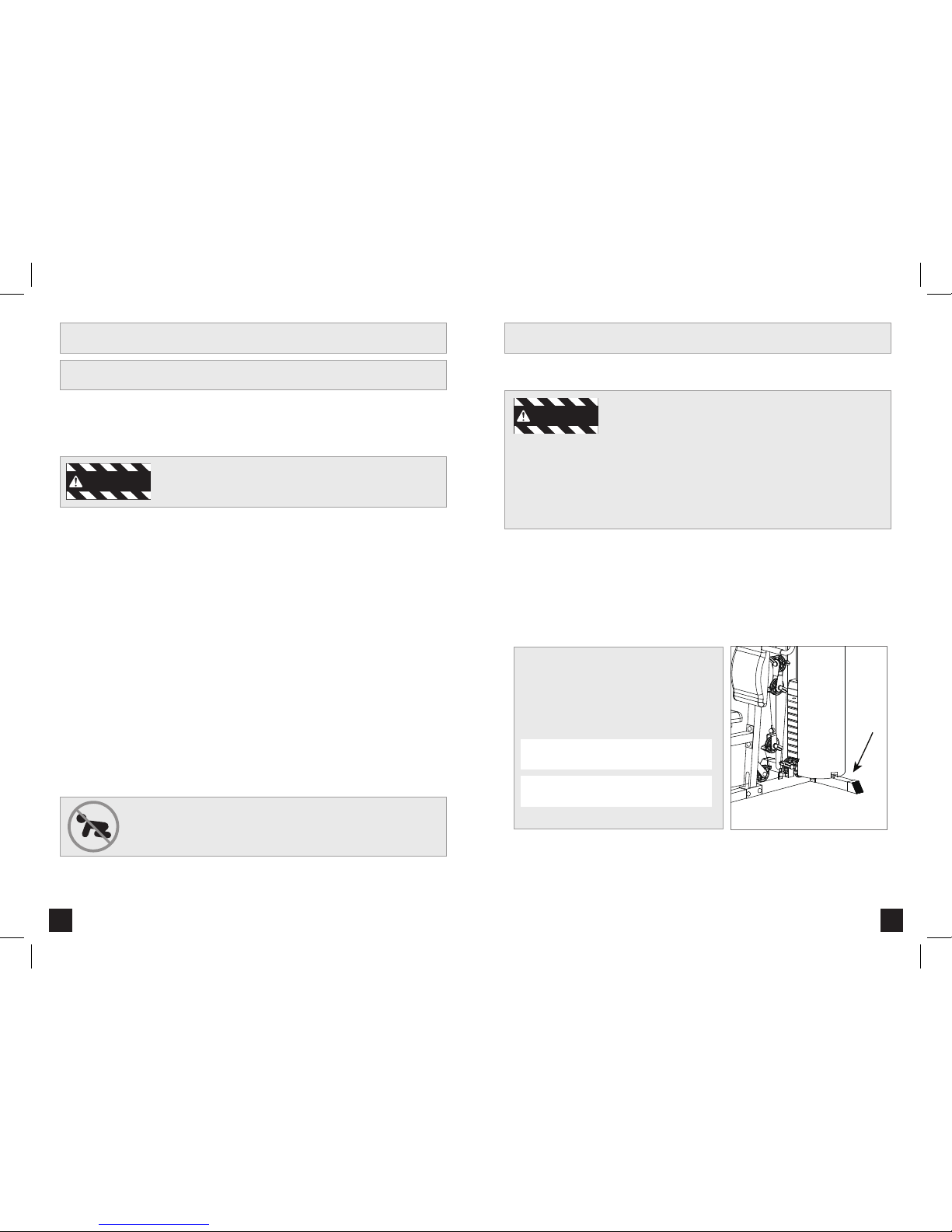
Before proceeding, find your home gym’s serial
number and model name located on the left rear
side of the base frame and enter it in the space
provided below.
ENTER YOUR SERIAL NUMBER AND
MODEL NAME IN THE BOXES BELOW:
SERIAL NUMBER :
MODEL NAME:
54
WARNING
WARNING

76
6
65
6
63
62
25
60
39
4
61
30 31 32 33
X1
X2
X1
59
54
24
58
7
416
17
29
15
9
6
5
13
12 66
8
1
11
2
20
19
18
3
39
38
46
47
36
35 45
44
43
42
37
5553
49
51
40
48
41
50
52
56 57
23 25 26
10
X1X1X1X1
X1
X1X1
X1
X1
X1X1
X1
1 2 1 1
X1
X11
1
1 1 1 1 1 1
2
1
121
2
X2
X2X4
4
X1
2 1
21
2
70 71
X X XXXXXX XX X X X6 17 642222 171 1 2 1
XXX X X X X X
22
X2
XXXX X X XX XX XX X2
64
1
27
X1
28
X4
69
XXXXX X X X X X1
34
14
X1
1
2
3
4
5
6
7
8
9
10
11
12
13
14
15
16
17
18
19
20
21
22
23
24
25
26
27
28
29
30
31
32
33
34
35
36
37
38
39
40
41
42
43
44
45
46
47
48
49
50
51
52
53
54
55
56
57
58
59
60
61
62
63
64
65
66
69
70
71
100
101
102
103
104
106
107
108
109
112
113
114
115
116
117
118
119
120
122
11
1
1
1
2
1
1
1
1
9
3
1
3
2
2
4
1
1
6
1
1
2
1
6
58
30
7
8
4
2
2
1
8
1
4
2
2
2
8
1
4
6
1
1
1
1
1
1
1
1
1
1
1
1
1
2
1
2
2
1
1
2
2
2
1
1
5
2
2
4
4
1
2
6
6
1
6
1
1
1
2
2
17
17
2
4
6
1
Base frame
Curve stabilizer
Front vertical support
Upper beam
Cross stabilizer
Seat support
Right butterfly arm
Left butterfly arm
Butterfly arm support
Seat tube support
Leg curler
Upper pulling bar
Lower pulling bar
Foam roller
H-cover board welding set(1)
Weight guidance rod
Weight protector
Weight selecting bar
Double pulley support
Single pulley support
Single pulley welding set
Spanner
Long Pin
selecting rod
hook
Chain (11 links)
H-cover board welding set (2)
Cover fixing plate with rod
Cover fixing plate
End cap for weight selecting bar (taper)
Bushing
foot cap
Round plastic cap
Short Pin
Square plastic cap
multi-angle kn
Fixing hook
Buffer
Round buffer
Round buffer
Cable guidance plate
Plastic ring for cable guidance
foam
foam
foam
Upper weight plate
50 x 50 x 1.5t x 536.5
D25.4 x 400 x 1.4T
156 x 40 x 40 x 3T
150 x 45 x 35 x 5T
D9.4 x 70L
D9.5 x 158
D8 x 80
D4.8 x 18 x 34
D1 x 204 x 310
D8 x 180 x 270
D26 x 32L
D29 x D12.1 x 9T
50 x 50 x 76.5 x 5T
D1 x 17.5L
D9.5 x 60L
50 x 50 x 18.5
3/8"-16UNC x 28L
3/8"-16UNC x 138L
R23 x 35 x 35
D16.5 x 80.5 x 24 x 32
D16 x D10.5 x 5.5T
D47 x D90 x 250L
D23xD80x165L
D23 x D35 x 127L
280 x 100 x 80
Lower weight plate
backrest
seat
Cable (weight—upper beam)
Cable (butterfly arms)
Cable (leg curler)
Weight pin
Weight washer
Weight sleeve
Raised pulley
Flat pulley
Ankle strap
Round cap Φ50.8
Bushing
Rubber buffer
Square plug
Insert plug
Square hollow cap
Bushing
Arm curl pad support
Arm curl pad
Butterfly hand grip 2
Spring knob 1
Bolt M10*75L
Flat washer
Nylon nut M10
Bolt M10*65L
Bolt M10*70L
Flat washer
Nylon nut M12
Bolt M10*95L
Bolt M12*80L
Bolt M10*60L
Bolt M12*150L
Bolt
Bolt M10*25L
Bolt M6*15L
Flat washer
Strap
Bolt M10*55L
Flat washer
Allen bolt
370 x 200 x 42
695 x 225 x 50
240 x 150 x 290 x 50
3180mm
1810mm
2120mm
D10.5 x 56.5L
D47.5 x D13 x 3T
D56 x D27 x 23.2
D90 x D10 x 28.5
D90 x D10 x 24
295 x 95mm
D50.8 x 16
35 x 35 x 25
25 x 25 x 13L
D57 x D38.5 x 107L
55 x 55 x 45 x 45 x 36L
D18 x D10 x 14.5
500 x 250 x 50
M10 x 1.5 x 75L
D20 x D11 x 2T
M10 x 1.5 x 10T
M10 x 1.5 x 65L
M10 x 1.5 x 70L
D24 x D13.5 x D2.5T
M12 x 1.75 x 12T
M10 x 1.5 x 95
M12 x 1.75 x 80L
M10 x 1.5 x 60L
M12 x 1.75 x 150L
1/2"-13UNC x 25L
M10 x 1.5 x 25L
M6 x 1 x 15L
D14 x D6.5 x 0.8T
M10 x 1.5 x 55L
D28 x D14 x 2T
M8 x 1.25 x 25L
#ITEM #ITEMDESCRIPTION DESCRIPTION SPECIFICATION SPECIFICATIONQTY QTY
PARTS LIST:

100
101
102
101
101
104
32
102
101
5
2
1
35
16
114
114
120
120
5
x1
x6
x2
x8
117
118
x4
x58
106
101
x30
x2
102
107
104
x7
103
x8
100
113
x8
112
115
x2
116
x2
108
122
x6
x4
114
x2
x1
109
x1
119
x2
120
98
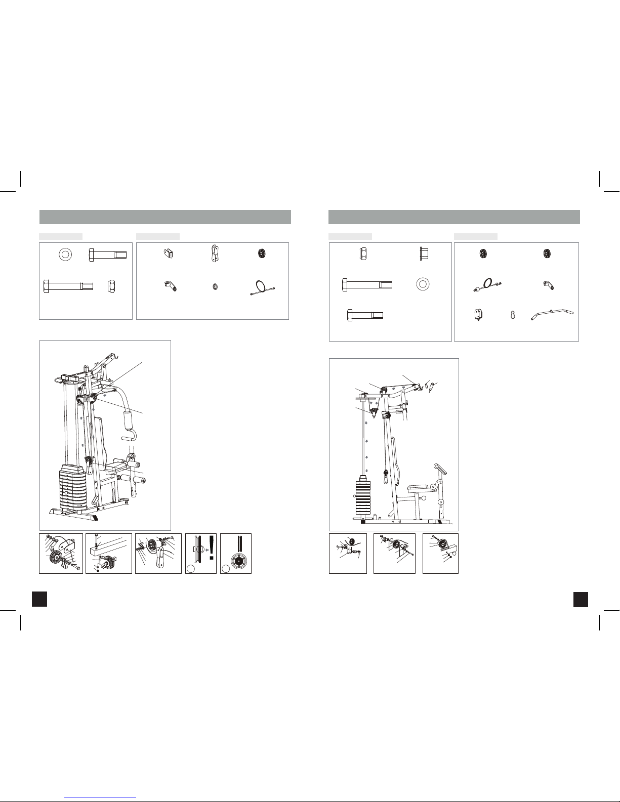
ASSEMBLY STEP 1
HARDWARE BAG 1: KEY COMPONENTS:
A Attach the weight guidance rod (16) and assemble them to the rear stabilizer through 2 bolts (114) and 2
flat washers (120).
B Fix the front stabilizer (2) and cross stabilizer (5) onto the base frame (1) by using 4 foot caps (32), 1 square
plastic cap (35), 2 bolts (104), 2 bolts (100), 8 flat washers (101) and 4 nylon nuts (102).
ASSEMBLY ADVICE:
IT IS RECOMMENDED THAT YOU DO NOT TIGHTEN SCREWS AND BOLTS COMPLETELY DURING ASSEMBLING.
PLEASE DO MAKE SURE ALL PARTS ARE WELL TIGHTENED AFTER COMPONENTS ARE IN PLACE.
ASSEMBLY INSTRUCTIONS
M12*1.75*150L
M10*1.5*95L
M12*1.75*80L
M10*1.5*75L
M10*1.5*70L
M10*1.5*65L
M10*1.5*60L
M10*1.5*55L
D14*D6.5*0.8T
D20*D11*2T
D24*D13.5*2.5T
D28*D14*2.5T
M12*1.75*12T
M10*1.5*10T
1/2”-13UNC*25L M6*1*15L
M10*1.5*25L M8*15L
Square plastic cap (35)
50 x 50 x 18.5 Qty:1
Foot cap (32)
50 x 50 x 76.5 x 5T Qty:4
Flat washer (101)
D20 x D11 x 2T Qty:8
Nylon nut (102)
M10 x 1.5 x 10T Qty:4
Bolt (104)
M10 x 1.5 x 70L Qty:2
Bolt (100)
M10 x 1.5 x 75L Qty:2
Flat washer (120)
D28 x D14 x 2T Qty:2
Weight guidance
rod (16)
Qty:2
Bolt (114)
1/2”-13UNC x 25L Qty:2

10 11
ASSEMBLY STEP 2 ASSEMBLY STEP 3
HARDWARE BAG 2: HARDWARE BAG 3:
120
114
16
39
15
122
101
104100
101
102
101
3
16
104
101
101
102
10
39
15
61 62
122
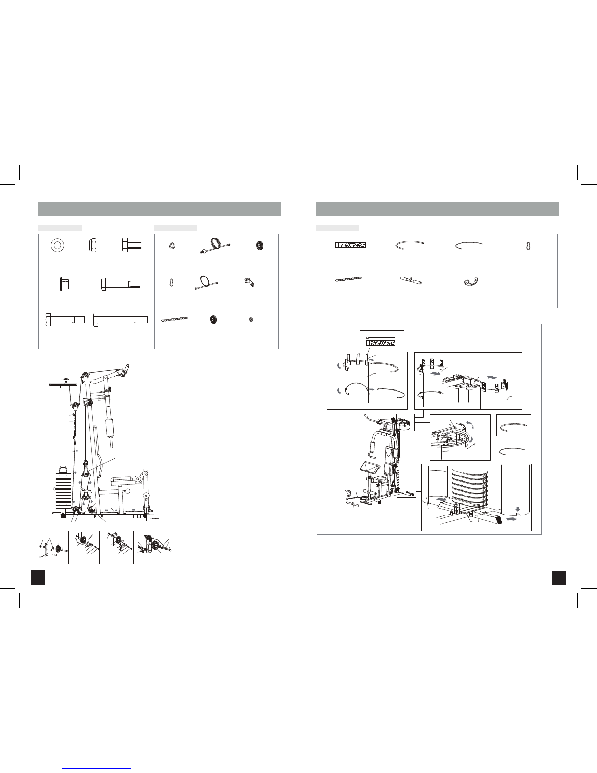
Assemble the seat tube support (10) to the base
frame (1) with 2 bolts (104), 4 flatwashers (101) and
2 nylon nuts (102). Then after fixing the front vertical
support (3) to the base frame (1) by using 2 bolts
(100), 4 flat washer (101) and 2 nylon nuts (102),
assemble the seat tube support (10) with the front
vertical support (3) by using 2 bolts (104), 4 flat
washers (101) and 2 nylon nut (102).
Thread the H-cover board welding (15) and 2
buffers
(39) from the bottom, and assemble the H-cover
board welding (15) with 2 Allen bolt(122).
Fix the rubber buffer (61) and 4 square plug (62) onto
the front vertical support (3).
Continuing to assemble 11 lower weight plate (47)
and 1 upper weight plate (46) through the weight
guidance rod (16), inset the weight selector (18)
through the hole of weights and fix the weight
sleeve (55) down from the upper weight (46) by
means of weight pin (53) and the weight washer
(54). Finally put 2 rubber buffer (40) on the upper
bottom of the weight guidance rod (16) and insert
selecting rod (24).
A
B
C
A
24
40
18
53
55
46
54
47
Round buffer (39)
Qty:2
Square plug (62)
25 x 25 x 13L Qty:4
Flat washer (101)
D20 x D11 x 2T Qty:12
Nylon nut (102)
M10 x 1.5 x 10T Qty:6
Round buffer (40)
Qty:2
selecting rod (24)
D9.5 x 158 Qty:1
Weight selecting
bar(18) Qty:1
Weight pin (53)
D10.5 x 56.5L Qty:1
Weight sleeve (55)
D56 x D27 x 23.2 Qty:1
Weight washer (54)
D47.5 x D13 x 3T Qty:1
Bolt (104)
M10 x 1.5 x 70L Qty:4
Rubber buffer (61)
Qty:1
H-cover board
welding set (15) Qty:1
Bolt (100)
M10 x 1.5 x 75L Qty:2
Allen bolt (122)
M8 x 15L Qty:2
KEY COMPONENTS: KEY COMPONENTS:

12 13
ASSEMBLY STEP 4 ASSEMBLY STEP 5
Attach 2 H-cover board welding set (27) to the upper
beam (4) with 4 bolts (122).
Assemble the upper beam (4) onto the front vertical
support (3) and weight guidance rod (16) by using 2
bolts (100), 4 flat washers (101), 2 nylon nut (102),
2 bolts (114), 2 flat washers (120) and cover each
end with 4 square plastic cap (35).
Fix the butterfly arm support (9) onto the upper
beam (4) by using 1 bolt (113), 2 flat washers
(106) and 1 nylon nut (107), and then fix the
multi-angle knob (36) and 1 fixing hook (37) onto
the butterfly arm support (9).
A
B
A
114
120
35 4
35
101
102
101
100
122
27
Square plastic cap (35)
50 x 50 x 18.5 Qty:4
H-cover board welding set (27)
Qty:2
Allen bolt (122)
M8 x 15L Qty:4
Flat washer (101)
D20 x D11 x 2T Qty:4
Bolt (114)
1/2”-13UNC x 25L Qty:2
Nylon nut (102)
M10 x 1.5 x 10T Qty:2
Bolt (100)
M10 x 1.5 x 75L Qty:2
Flat washer (120)
D28 x D14 x 2T Qty:2
Fixing hook (37)
3/8”-16UNC x 138L
Qty:1
multi-angle knob (36)
3/8”-16UNC x 28L
Qty:1
Bolt (113)
M12 x 1.75 x 150L Qty:1
Flat washer (106)
D24 x D13.5 x 2.5T
Qty:2
Nylon nut (107)
M12 x 1.75 x 12T
Qty:1
HARDWARE BAG 4: HARDWARE BAG 5:
9
113
106
107
106
37
36
KEY COMPONENTS: KEY COMPONENTS:

14 15
ASSEMBLY STEP 6 ASSEMBLY STEP 7
Attach the 2 buffer (38) onto right & left butterfly
arm (7&8), then fix the right & left butterfly arm to
the
butterfly arm support (9) by using 2 flat washers
(101)
and 2 nylon nut (102).
Slide the foam (43) onto the butterfly arm, then
assemble the butterfly hand grip (70) to the butterfly
arm
by using the bolt (104) and flat washer (101).
Insert a square hollow cap (64) and seat support (6)
into the seat tube support (10). After that the square
plastic cap (35) in the corresponding place of the
seat support.
Fix the seat (49) to their corresponding parts by the
flat washer (101) and bolts (103).
Thread the foam roller (14) through the seat support
(6), then coat the foam roller with the foam (44).
Fix the backrest (48) onto the front vertical tube by 2 bolts
(103) and 2 flat washer (101).
Attach the arm curl pad (69) onto the pad support (66) by
means of 2 bolt (116) and 2 flat (117).
Fix the insert plug (64A) and arm curl pad support (66) into
the leg curler (11). Then fix the leg curler (11) attach to the
seat support (6) by using 2 bushing (31), 2 flat washer (106)
,1 nylon nut (107), 1 bolt (109) and 1 round plastic cap (59)
and 1 long pin (23). Place the short pin (34) into the seat
support (6).
Thread the foam roller (14) through the leg curler (11), then
coat the foam roller with the 2 foam (44).
A
B
C
D
E
A
B
C
D
6
101103
49
35
102
101
7
8
104
101
43
70
38
14
44
64
48
103
101
31
109
106
23
107
59
11
14
117
116
69
66
44
34
63
66
103
101
31
109
106
23
107
59
11
14 44
34
63
Square plastic cap (35)
50 x 50 x 18.5 Qty:1
foam (43)
D47 x D90 x 250L Qty:2
Flat washer (101)
D20 x D11 x 2T Qty:6
Square hollow cap (64)
55 x 55 x 45 x 45 x 36L Qty:1
Nylon nut (102)
M10 x 1.5 x 10T Qty:2
Bolt (103)
M10 x 1.5 x 65L Qty:2
foam (44)
D23 x D80 x 165L Qty:2 Long pin (23)
D9.4 x 70L Qty:1
Flat washer (106)
D24 x D13.5 x 2.5T Qty:2
Flat washer (101)
D20 x D11 x 2T Qty:2
Short pin (34)
D9.5 x 60L Qty:1
Insert plug (63)
D57 x D38.5 x 107L Qty:1
Bolt (103)
M10 x 1.5 x 65L Qty:2
Bushing (31)
D29 x D12.1x 9T Qty:2
Round cap (59)
D50.8x16 Qty:1
Bolt (109)
M12 x 1.75 x 85L Qty:1
foam (44)
D23 x D80 x 165L Qty:2
Nylon nut (107)
M12 x 1.75 x 12T Qty:1
Bolt (116)
M6 x 15L Qty:2
lat washer (117)
D14 x D6.5 x 0.8T Qty:2
Bolt (104)
M10 x 1.5 x 70L Qty:2
HARDWARE BAG 6: HARDWARE BAG 7:KEY COMPONENTS: KEY COMPONENTS:
112
56
101
101
102
20
42
41
112
101
19
56
102
51
41
42
41
20
108
101
101
110
101
41
42
42
!
56 57
FIG A
FIG A
FIG B
FIG B
FIG C
FIG C
16 17
ASSEMBLY STEP 8 ASSEMBLY STEP 9
Connection of cable (butterfly arm) (51): the way
going as drawing. Hooking one of the cable to the
right butterfly arm (7). At the same time, fixing the
raised pulley (56) into the single pulley support
(20) (FIG A) by using 1 bolt (112), 2 flat washer
(101), 2 plastic ring for cable guidance (42), 2
cable guidance plate (41), 1 nut (102).
Assembly the single pulley support (20) with pulley
(56) onto the right butterfly (FIG B) by means of 1
bolt (108), 2 flat washer (101) and 1 nut (110).
Slide the other end of the cable along the rasied pulley
(56)
, after going downward and upwards through the
double pulley support (19) which at the same time
already fixing with the 2
raised pulley (56)
using 2
bolt (112), 4
flat washer (101), 4 plastic ring for
cable
guidance (42), 2
cable guidance plate (41)
, 2 nylon
nut (102). And then the other end will be joined to the
left butterfly arm (8) (FIG C).
NOTE: DO NOT MISUSE FLAT PULLEY (57) AT THIS STEP.
NOTE (FIG A ): Make sure you use flate pulley (57) and
assemble cable (50) at this step.
NOTE (FIG C ): Make sure you use raised pulley (56)
and assemble cable (50) at this step.
Connection of cable (50): hooking the end cable
on the
head of upper beam and then the way going
as drawing.
During the assembly, you must at the same time fix the
2 flat pulley (57) by using 1 bolt (103), 2 busing (65)
and 1 nylon nut (102) and 1 raised pulley (56) onto the
upper beam (FIG C) and also 1 raised pulley (56) onto
the upper beam by using 1 bolt (112), 2 flat washer
(101), 2 plastic ring (42), 2 cable guidance plate (41)
(FIG B), and 1 flat pulley (56) between to the single
pulley support (21) with the same bolt of FIG B.
The other end of cable will be jointed with the weight
select bar.
Fix the upper pulling bar (12) with the upper beam by
hook (25).
A
B
C
A
B
C
Flat washer (101)
D20 x D11 x 2T Qty:10
Single pulley support (20)
Qty:2
Double pulley support (19)
156 x 40 x 40 x 3T Qty:1
Raised pulley (56)
D90 x D10 x 28.5 Qty:3
Raised pulley (56)
D90 x D10 x 28.5 Qty:2
Flat pulley (57)
D90 x D10 x 24 Qty:2
Cable guidance plate (41)
D16.5 x 80.5 x 24 X 32 Qty:6
Cable guidance plate (41)
D16.5 x 80.5 x 24 X 32 Qty:1
Cable (butterfly arms) (51)
1810mm Qty:1
Cable (weight-upper beam) (50)
1810mm Qty:1
Single pulley welding
set (21) Qty:1
Plastic ring for
cable guidance (42)
D16 x 10.5 x5.57 Qty:6
Nylon nut (102)
M10 x 1.5 x 10T Qty:5
Bolt (108)
M10 x 1.5 x 95L Qty:2
Bolt (112)
M10 x 1.5 x 60L Qty:3
Nylon nut (102)
M10 x 1.5 x 10T Qty:4
Bushing (65)
D18 x D10 x 14.5 Qty:4
Flat washer (101)
D20 x D11 x 2T Qty:4
Bolt (103)
M10 x 1.5 x 65L Qty:2
Bolt (112)
M10 x 1.5 x 60L Qty:2
HARDWARE BAG 8: HARDWARE BAG 9:
25 12
FIG A FIG C
FIG C
FIG C
112
101
41
42
21
56
102
101
50
102
65
103
57
FIG B
FIG B
FIG C
102
101
101
42
112
41
56
KEY COMPONENTS: KEY COMPONENTS:
Hook (25)
D8 x 80 Qty:1
Upper pulling bar (12)
Qty:1
29
28
28
29
C
D
B
A
118
17
17
27 2
17
28
17
17
28
29
28
118
13
25
26
58
18 19
ASSEMBLY STEP 10
(1)Connection of cable (52): the way going as
drawing. From the first pulley support on the leg
curler (11), 1 flat pulley (57) is fixed inside the
leg curler as exploded drawings (FIG A) by using
1 bolts (103), 2 bushings (65) and 1 nylon nut
(102). After going downward and upward through
2 raised pulley (56) by 1 bolt (119), 2 flat washer
(101), 1 plastic ring (42), 1 cable guidance (41),
1 nylon nut (102) (FIG B & E/C), the other end will
be joined to the main base by a spring hook (25).
Connection of cable (51): the way going as draw-
ing. Join one end of cable (51) and pulley (56)
by 1 bolt (112), 2 flat washer (101) and 1 nylon
nut (102). Through the pulley which already fixed,
then going downward and upward through the
relative pulleys (56), the other end will be joined
with the cable by using 1 chain (26) and 2 hook
(25) (FIG D).
A
B
ASSEMBLY STEP 11
Assemble 2 weight protector (17) around the weights by using 4 cover fixing plat with rod (28), 2 cover
fixing plate (29), 8 strap (118).
Connecting ankle strap (58) and lower pulling bar (13) with cable (52) by using 1 hook and 1 chain.
A
B
Flat washer (101)
D20 x D11 x 2T
Qty:12
Metal Bushing (65)(Middle)
D18 x D10 x 14.5 Qty:2
Nylon nut (102)
M10 x 1.5 x 10T
Qty:7
Bolt (119)
M10 x 1.5 x 55
Qty:1
Bolt (103)
M10 x 1.5 x 65L
Qty:1
Bolt (115)
M10 x 1.5 x 25L
Qty:2
Bolt (112)
M10 x 1.5 x 60L
Qty:3
Strap (118)
Qty:8
Cover fixing plate (29)
D8 x 180 x 270 Qty:4
Cover fixing plate with rod (28)
D1x 204 x 310 Qty:4
NOTE: THERE IS ONLY ONE CABLE GUIDANCE(41)
BEEN USED IN FIG B.
Raised pulley (56)
D90 x D10 x 28.5
Qty:4
Hook (25)
D8 x 80 Qty:2
Hook (25)
D8 x 80 Qty:1
Chain (11 links) (26)
D8 x 80 Qty:1
Ankle strap (58)
295 x 95mm Qty:1
Chain (11 links) (26)
D8 x 80 Qty:1
Lower pulling bar
(13)
Qty:1
Cable guidance plate (41)
D16.5 x 80.5 x 24 X 32
Qty:7
Cable
(butterfly arms) (51)
1810 Qty:1
Plastic ring for
cable guidance (42)
D16 x 10.5 x5.57 Qty:7
Bushing (65)
D18 x D10 x 14.5
Qty:2
Cable (leg curler) (52)
2120 Qty:1
Flat pulley (57)
D90 x D10 x 24
Qty:1
52
26
25
51
115
115
101
102
102
101
101
42
112
41
56
FIG E/C
FIG A
FIG D
FIG BFIG E/C
57
102 65 103
FIG A
42
41
119
102
101
101
56
FIG B
101
112
101
102
41
42
56
51
FIG D
HARDWARE BAG 10: KEY COMPONENTS: KEY COMPONENTS:
STRETCH FIRST
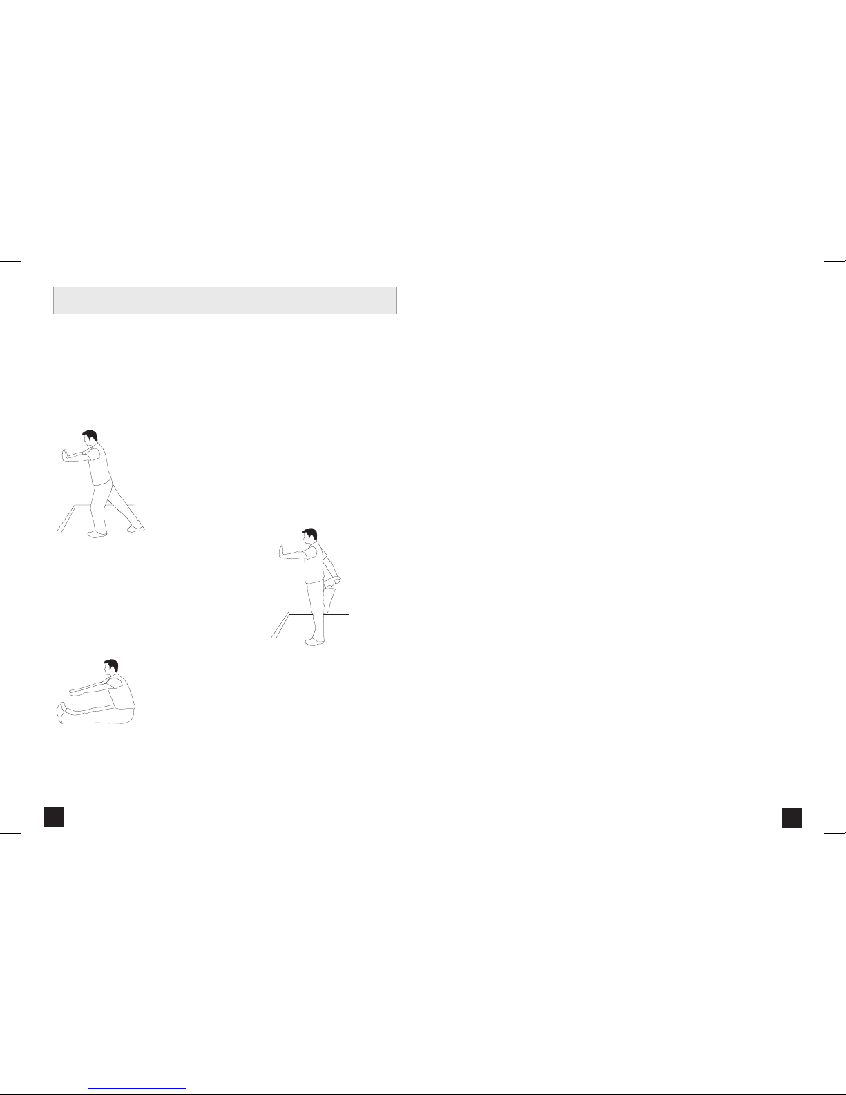
Before using your product, it is best to take a few minutes to do a few gentle stretching exercises.
Stretching prior to exercise will improve flexibility and reduce chances of exercise related injury. Ease
into each of these stretches with a slow gentle motion. Do not stretch to the point of pain. Make sure
not to bounce while doing these stretches.
1. STANDING CALF MUSCLE STRETCH
Stand near a wall with the toes of your left foot about 18" from the wall,
and the right foot about 12" behind the other foot. Lean forward, pushing
against the wall with your palms. Keep your heels flat and hold this position
for a count of 15 seconds. Make sure that you do not bounce while
stretching. Repeat on the other side.
2. STANDING QUADRICEP STRETCH
Using a wall to provide balance, grasp your left ankle
with your left hand and hold your foot against the back
of your thigh for 15 seconds. Repeat with your right
ankle and hand.
3. SITTING HAMSTRING & LOWER BACK MUSCLE STRETCH
Sit on the floor with your legs together and straight out in front of you. Do
not lock your knees. Extend your fingers towards your toes and hold for a
count of 15 seconds. Make sure that you do not bounce while stretching.
Sit upright again. Repeat one time.
20 21
CONDITIONING GUIDELINES

DATE SET 1
EXERCISE WEIGHT REPS
SET 2 SET 3
WEIGHT REPS WEIGHT REPS
DATE SET 1
EXERCISE WEIGHT REPS
SET 2 SET 3
WEIGHT REPS WEIGHT REPS
DATE SET 1
EXERCISE WEIGHT REPS
SET 2 SET 3
WEIGHT REPS WEIGHT REPS
DATE SET 1
EXERCISE WEIGHT REPS
SET 2 SET 3
WEIGHT REPS WEIGHT REPS
DATE SET 1
EXERCISE WEIGHT REPS
SET 2 SET 3
WEIGHT REPS WEIGHT REPS
DATE SET 1
EXERCISE WEIGHT REPS
SET 2 SET 3
WEIGHT REPS WEIGHT REPS
DAILY LOG SHEETS
22 23

TROUBLESHOOTING MAINTENANCE
Your home gym is designed to be reliable and easy to use. However, if you experience a problem, please
refer the troubleshooting guide listed below.
Cleanliness of your home gym and its operation environment will keep maintenance problems and service
calls to a minimum. For this reason, we recommend that the following preventive maintenance schedule
be followed.
AFTER EACH USE (DAILY)
• Wipe upholstery, handgrips, bars, and frame (if needed) with a mild cleaning solution.
EVERY WEEK
• Lubricate guide rods with a spray or gel silicone lubricant.
• Inspect cable ends and cable insulation for damage.
EVERY MONTH - IMPORTANT!
•
Inspect all frame bolts and tighten it when needed.
Please contact your local dealer with questions about applying lubricant to your home gym.
ADJUSTING CABLE TENSION
Regularly check the cable tension of your home gym. If excesive slack exists adjust cable tension by moving
one or both pulleys to the inner mounting position in the dual floating pulley bracket. Cable tension may also
be adjusted using the threaded cable end on single pulley bracket and weight stack Twist threaded end to
adjust tension and then tighten lock nut.
NOTE: Always maintain at least ½˝ of threaded bolt in bayonet.
PROBLEM:
The cables feel rough and are noisy during use.
SOLUTION:
Verify the following:
IS THERE ANY NOTICABLE DAMAGE TO THE CABLES?
IF YES:
• Contact customer tech support and replace the cable(s).
IF NO:
• Verify that all cables are secured into the pulleys.
• Verify that the weight stack guiderods are lubricated.
• Verify that there is no excessive slack in the cables.
NOTE: If there is excessive slack adjust cable tension (see next page)
PROBLEM:
Weight selector pin cannot be inserted.
SOLUTION:
Verify the following:
ARE THE HOLES ALLIGNED THROUGH THE WEIGHT PLATE AND BAYONET?
IF YES:
• Verify that the selector pin isn’t bent or damaged.
IF NO:
• Adjust threaded bolt on top plate so that the holes in the bayonette align with the
weight plate.
NOTE: Always maintain at least ½˝ of threaded bolt in bayonette.
The following information may be asked of you when you call. Please have these items readily available:
• Model Name
• Serial Number
• Date of Purchase (receipt or credit card statement)
In order for your local dealer to service your home gym they may need to ask detailed questions about the
symptoms that are occurring. Some troubleshooting questions that may be asked are:
• How long has this problem been occurring?
• Does this problem occur with every use? With every user?
• If you are hearing a noise, does it come from the front or the back? What kind of noise is it
(thumping, grinding, squeaking, chirping etc.)?
• Has the machine been lubricated and maintained per the maintenance schedule?
Answering these and other questions will give the technicians the ability to send proper replacement parts
and the service necessary to get you and your Treo Fitness home gym functioning again!
24 25

LIMITED HOME-USE WARRANTY
WEIGHT CAPACITY = 120 kg / 264 lbs
Who IS covered:
What IS covered:
What IS NOT covered:
The original owner and is not transferable.
Repair or replacement of defective part and is the sole remedy of the warranty.
Normal wear and tear, improper assembly or maintenance, or installation of parts or accessories not
originally intended or compatible with the equipment as sold.
Damage or failure due to accident, abuse, corrosion, discoloration of paint or plastic, neglect, theft,
vandalism, fire, flood, wind, lightning, freezing, or other natural disasters of any kind, power reduction,
fluctuation or failure from whatever cause, unusual atmospheric conditions, collision, introduction of
foreign objects into the covered unit, or modifications that are unauthorized or not recommended by
Treo Fitness.
Incidental or consequential damages. Treo Fitness is not responsible or liable for indirect, special
or consequential damages, economic loss, loss of property, or profits, loss of enjoyment or use, or
other consequential damages of whatsoever nature in connection with the purchase, use, repair or
maintenance of the equipment.
Equipment used for commercial purposes or any use other than a single family or Household, unless
endorsed by Treo Fitness for coverage.
Delivery, assembly, installation, setup for original or replacement units or labor or other costs associated
with removal or replacement of the covered unit.
Any attempt to repair this equipment creates a risk of injury. Treo Fitness is not responsible or liable
for any damage, loss or liability arising from any personal injury incurred during the course of, or as a
result of any repair or attempted repair of your fitness equipment by other than an authorized service
technician. All repairs attempted by you on your fitness equipment are undertaken AT YOUR OWN RISK
and Treo Fitness shall have no liability for any injury to the person or property arising from such repairs.
26
D:
Entsorgungshinweis
TREO Fitness - Produkte sind recyclebar. Führen Sie das Gerät am Ende der Nutzungsdauer einer
sachgerechten Entsorgung zu (örtliche Sammelstelle).
GB:
Waste Disposal
TREO Fitness products are recyclable. At the end if its useful life please dispose of this article correctly and
safely ( local refuse sites).
F:
Remarque relative à la gestion des dèchets
Les produits TREO Fitness sont recyclables. A la fin sa durrèe d`utilisation, remettez I´appareil à un centre
de gestion de dèchets correct (collecte locale).
NL:
Verwijderingsinstructie:
TREO Fitness producten zijn recycleerbaar. Breng het apparaat aan het einde van de gebruiksduur voor
recycling naar een vakkundig verzamelpunt.
E:
Informaciones para la evacuaciòn
Los productos de TREO Fitness son riciclables. Cuando se termina la vida ùtil de un aparato o una màquina,
entrèguelos an una impresa local de eleiminaciòn de residuos para su reciclaje.
I:
Indicazione sullo smaltimento
I prodotti TREO Fitness sono reciclabill. Quando I` apparecchio non servirà più, portatelo in un apposito
punto di raccolta della Vostra città (Punti di raccolta comunall).
PL:
Wskazòwka dotyczàca usuwania odpadòw.
Producty firmy TREO Fitness podlegajà recyklingowi. Pod koniec okresu o`ywalnoÈcl pros`z oddac
urzàdzenie do wlaÈciwego punkto usuwania odpadòw (lokalny punkt zbiorczy).
27
•
•
•
•
•
•
•
•
*
Please consult your local dealer for more warranty details.

G102 070210 © 2010 Treo Fitness Products | Made in China
Table of contents
Other Treo Fitness Home Gym manuals


