TREW 1500 Series Instruction Manual

SERIES 1500
24VDC MOTORIZED DRIVER ROLLER
HCAT30 POP-UP DIVERT SECTION
INSTALLATION &
MAINTENANCE MANUAL
1.800.571.8739 poweredbyTREW.com info@trewautomation.com

www.poweredbyTrew.com
1.800.571.8739
REV A HCAT30 - Installation and Maintenance Manual
TABLE OF CONTENTS
OVERVIEW 1.1
COMPONENTS 2.1
HCAT30 Pop-Up Base 2.1
Types of MDR 2.9
Replacement of MDR 2.10
Carrier Roller 2.14
Replacement of Carrier Roller 2.14
Replacement of Carrier Roller for Top Surface 2.14
Drive Belts (O-Bands) 2.15
Proximity Sensors 2.15
Proximity Sensor Adjustment 2.15
PREVENTATIVE MAINTENANCE 3.1
SUPPORT 4.1
Troubleshooting A Dead Zone On The Conveyor 4.2
Controller Check 4.2
Power Supply 4.2
Motor Control Card / Motorized Drive Roller Checks 4.3
No Voltage to the Motor Control Card 4.4
Troubleshooting Guide 4.5
i
i

www.poweredbyTrew.com
1.800.571.8739
REV A HCAT30 - Installation and Maintenance Manual
1
OVERVIEW

REV A HCAT30 - Installation and Maintenance Manual
www.poweredbyTrew.com
OVERVIEW 1
Theory Of Operation
The HCAT30 pop up divert module provides the ability to divert packages o a conveyor
system at moderate rates. The HCAT30 is designed to divert packages at a 30 degree angle
relative to the main conveyor line, while not stopping the package during
the divert process.
The HCAT30 consists of xed direction rollers, divert wheels tting between the xed rollers,
and a lifting mechanism that raises and lowers the divert wheel module.
All actuated motions of the HCAT30 are directed by an external control system.
1.1

www.poweredbyTrew.com
1.800.571.8739
REV A HCAT30 - Installation and Maintenance Manual
2
COMPONENTS

REV A HCAT30 - Installation and Maintenance Manual
www.poweredbyTrew.com
COMPONENTS 2
2.1
Components
The HCAT30 is broken down into three sub-assemblies, top surface rollers, pop-up base and
lift drive assembly. Assembly of all three sub-assemblies is shown in Figure 1. First two images
(2.1) will show components of top surface and lift drive assembly. Third image (2.2) shows
the connection point of all three sub-assemblies. Fourth image (2.3) shows the overview
of the HCAT30 and fth image (2.4) is the table of components:
Figure 1.1
Figure 1.2

REV A HCAT30 - Installation and Maintenance Manual
www.poweredbyTrew.com
COMPONENTS 2
2.2
Figure 1.3

REV A HCAT30 - Installation and Maintenance Manual
www.poweredbyTrew.com
COMPONENTS 2
2.3
Figure 1.4

REV A HCAT30 - Installation and Maintenance Manual
www.poweredbyTrew.com
COMPONENTS 2
HCAT30 Pop-Up Base
Figure 2 (2.5) shows the assembly of the pop-up base. The rst image shows the
components of the carriage and divert wheel. Second and third image shows the components
that attach to the sides of the pop-up base plate. Fourth image is the orientation of the rollers.
Fifth image is the assembly of the pop-up base. Sixth image is the table of components.
2.4

REV A HCAT30 - Installation and Maintenance Manual
www.poweredbyTrew.com
COMPONENTS 2
2.5
Figure 2.1
Figure 2.2

REV A HCAT30 - Installation and Maintenance Manual
www.poweredbyTrew.com
COMPONENTS 2
2.6
Figure 2.3
Figure 2.4

REV A HCAT30 - Installation and Maintenance Manual
www.poweredbyTrew.com
COMPONENTS 2
2.7
Figure 2.5
Figure 2.6

REV A HCAT30 - Installation and Maintenance Manual
www.poweredbyTrew.com
COMPONENTS 2
Types of MDR
There are three types of MDR used in the HCAT30. The three types are the lift drive
assembly roller, the divert wheel drive assembly rollers and top surface drive roller. The divert
wheel drive assembly rollers drive the pop-up divert wheels. The lift device assembly roller
as oblong shape plates welded to each end to allow the mechanism to lift to the desired
height. Figure 3 shows the three types of motorized drive rollers.
2.9
Top Surface Drive Roller
Lift Drive Assembly Roller
Divert Wheel Drive Assembly Roller
REV A HCAT30 - Installation and Maintenance Manual
www.poweredbyTrew.com
COMPONENTS 2
Replacement of MDR
1 Turn o and Lockout / Tag-out all power to the conveyor section
2 Make sure that the Gear Ratio matches that of the roller that is being replaced.
Standard Gear Ratios would include: 12:1, 16:1, 24:1, 36:1, 64:1, and 96:1.
This is important if the conveyor system is comprised of more than one speed
3 The replacement roller should include:
a Motorized Drive Roller for BF and Gear Ratio
bHardware kit
i. star washers – qty. 2
ii. motor nut
iii. motor instructions
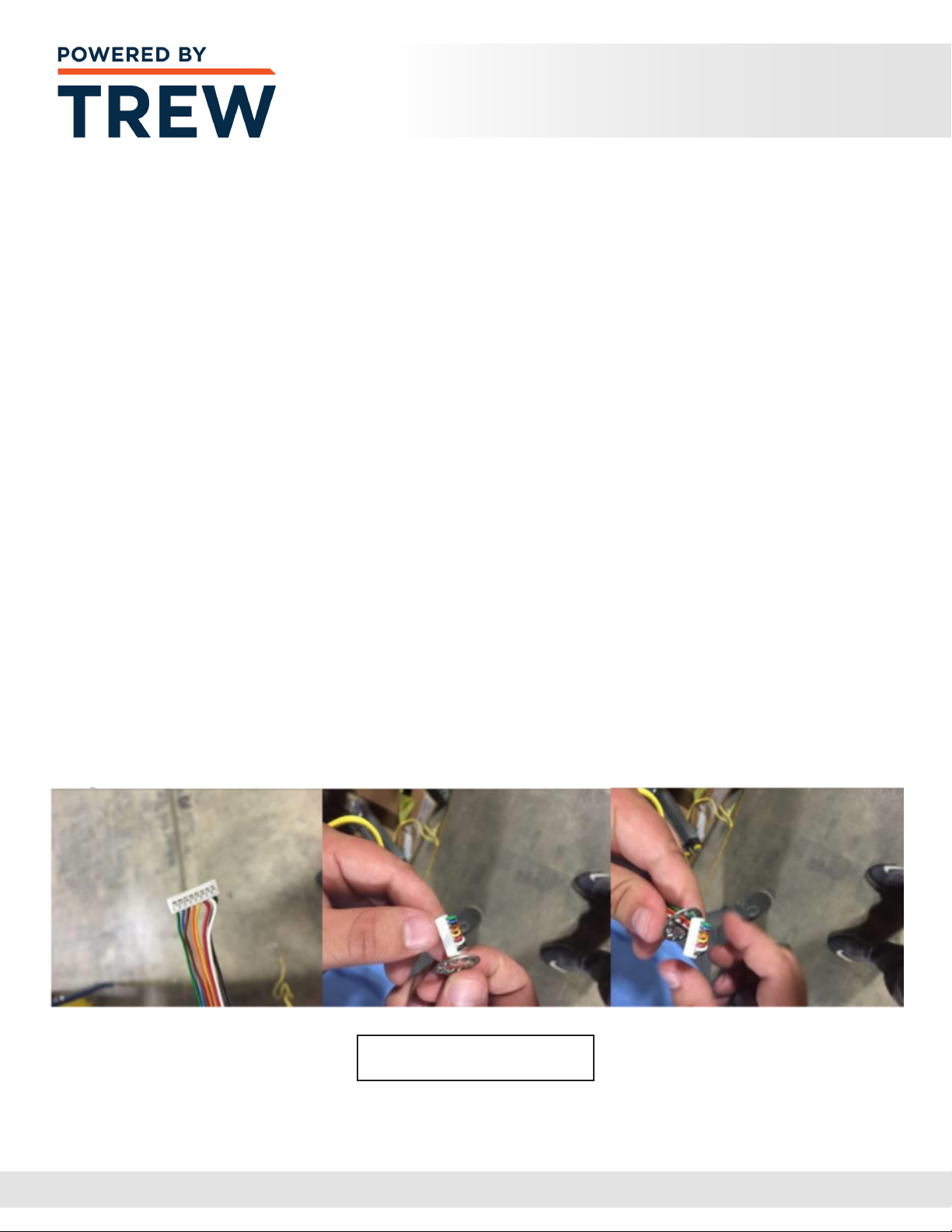
4 Install a star washer on the threaded motor shaft. Fold the wires perpendicular
to the connector and fan the wires down the backside of the connector.
When folding the wires over the top of the connector use care not to put too much
stress on the connector pins and try not to overlap and wires on top of other wires.
This will allow the connector to easily pass through the washer. Just simply bending
the wires at the connector and forcing the star washer over the wire can cause
damage to the insulation on the wires leading to failure of the MDR.
See image below for instruction
2.10
Fan & Fold Method

REV A HCAT30 - Installation and Maintenance Manual
www.poweredbyTrew.com
COMPONENTS 2
5 Utilizing the fold and fan method described above insert the MDR connector
into the hex hole and gently pull the cable extending from the motor through
6 Insert the threaded hex shaft into the hex hole. Push the spring loaded idler shaft
inwards and line the roller up with the hole. Release the idler shaft and allow it to pop
into the hole in the frame. See image below for an exploded view of the process
7 The replacement roller should include:
a Motorized Drive Roller for BF and Gear Ratio
bHardware kit
i. star washers – qty. 2
ii. motor nut
iii. motor instructions
8 The motor nut threads on to the motorized drive roller shaft, and should
be to the proper torque of: See Page 2.13 for Proper Torque Information.
Note: Torque is critical. Failure to properly torque the MDR will result in the
shaft spinning in the frame, twisting of the wires and failure of the MDR.
Exceeding this torque specication will also result in the conditions above.
2.11

REV A HCAT30 - Installation and Maintenance Manual
www.poweredbyTrew.com
COMPONENTS 2
9 Tools required to achieve proper torque can be seen in Figure 6
10 Plug the motor cable into the motor control card
11 Turn on power to the conveyor section
12 Check to see if roller operates by blocking the photo eye sensor of the zone
that is being serviced or the photo eye sensor located upstream with respect to ow
13 If the MDR does not operate review the Troubleshooting Section
These checks must be performed with the
power to the conveyor section turned “ON”.
Only qualied electricians should be allowed
to perform these checks. Failure to follow
this instruction may result in serious
personal injury and/or equipment damage.
2.12

REV A HCAT30 - Installation and Maintenance Manual
www.poweredbyTrew.com
COMPONENTS 2
EC110 and EC100:
30 ft-lbs +/- 5 ft-lbs
(40.7 N-M +/- 6 N-M)
ITOH:
22.5 ft-lbs +/- 5 ft-lbs
(30.5 N-M +/= 6 N-M)
EC310:
50 ft-lbs +/- 5 ft-lbs
(67.8 N-m +/- 6 N-m)
Gear Ratios Vary.
Proper Torque
2.13

REV A HCAT30 - Installation and Maintenance Manual
www.poweredbyTrew.com
COMPONENTS 2
Carrier Roller
The carrier roller is used to take the weight of the product and also distributes the
torque generated by the motorized drive rollers via o-belts, chain, timing belts, strip belts,
or full-width belts. Generally, no more than nine carrier rollers per motorized drive roller
are used in each zone.
Replacement of Carrier Roller:
1 Turn o and Lockout / Tag-out all power to the conveyor section
2 Use an appropriate tool to push in the spring loaded axle on the roller
and free that side of the axle from the frame of the conveyor
3 Carefully disengage the opposite end of the roller from the frame.
Make sure the axle is not pinched on the frame causing damage during removal
4 Remove the disengaged roller entirely from the frame section
5 Insert the axle of the replacement roller through the conveyor frame
6 Use an appropriate tool to push in the spring loaded axle and lower the roller
into position, aligning the axle with the hex hole in the conveyor frame
7 Unlock and turn on the power to the conveyor section
Replacement of Carrier Roller for Top Surface:
1 Turn o and Lockout / Tag-out all power to the conveyor section
2 Remove retaining plate
3 Remove the roller end that was in retaining plate
4 Pull roller out from other side of frame
5 Place spring loaded axle opposite of retaining plate end, aligning the axle
with the hex hole in the conveyor frame
6 Place other end of roller in frame and replace retaining plate
2.14

REV A HCAT30 - Installation and Maintenance Manual
www.poweredbyTrew.com
COMPONENTS 2
Drive Belts (O-Bands)
MDR conveyor utilizes drive belts to connect individual rollers together to create a Zone.
The drive belts can be O-bands or V belts, depending upon load and speed requirements
of the conveyor. Over time the drive belts can exhibit wear. O-bands in particular can wear
or stretch, eventually allowing excessive slippage in the roller groove. When this happens,
the rollers in the zones may not rotate and inadequately convey packages.
Proximity Sensors
There are two proximity sensors that provide control feedback, indicating the vertical
position of the transfer mechanism, or cam. The sensors are adjusted at the factory,
but eld adjustment may be required from time to time.
Proximity Sensor Adjustment
Correct positioning, or adjustment, of the proximity sensors will allow the sensors to
detect the ag at the max position and the divert bank at the minimum position respectively.
To check the sensor position the Cam lifting rollers should be rotated and the sensor detection
lights should be monitored. When the cam is nearly in the up position, the up position
proximity sensor light should blink on and remain on. When the cam is nearly in the down
position the down position proximity sensor will blink on and remain on. Both sensors should
be sensing with very little travel remaining on the roller frame in the up and down position.
If adjustment is required, loosen the jam nuts retaining the sensor, and adjust the
vertical position of the sensor to achieve the desired result then tighten the jam nut.
See Figures 11 and 12 to see the relative positions of the ags and sensors.
Note: Adjustment of the sensor performance aects the controls operation
of the divert module. Proper mechanical performance of the divert module
is achieved when the control system raises the divert bank to the upper most
position for the appropriate amount of time to divert packages then lowers the
divert bank to the lowest position to allow other packages to ow straight over
the rollers. Adjustment should be performed with someone knowledgeable
of the control systems.
2.15

REV A HCAT30 - Installation and Maintenance Manual
www.poweredbyTrew.com
COMPONENTS 2
Shown in this image is the down position proximity sensor. The divert bank
is in the raised position. The sensor will read the ag (frame) to indicate when
the divert bank is in the down position.
Shown in this image is the up position proximity sensor and ag.
The divert bank is in the raised position. The sensor will read the ag (frame)
to indicate when the divert bank is in the up (raised) position.
2.16
Other manuals for 1500 Series
1
Table of contents
Other TREW Accessories manuals

Popular Accessories manuals by other brands

SPALDING
SPALDING M886548 owner's manual

Siko
Siko MSA213C quick start guide

Seeley
Seeley Climate Wizard CW-P15 Installation operation & maintenance

Omcan
Omcan BB-CN-0012E-SH instruction manual

Innovative Technology
Innovative Technology Justin JP-140-3000i user manual

Bushnell
Bushnell 78-4502 instruction manual


PCB Piezotronics
PCB Piezotronics IMI SENSORS 603C11/-0006 Installation and operating manual

Eldom
Eldom ON10 user manual

Balluff
Balluff BTL7-V50D-M C003 Series Condensed guide

SICK
SICK WLA26 00 Series operating instructions

SICK
SICK C30-21 163 Series operating instructions

Tektronix
Tektronix CT-6 instruction manual