TREW 1500 Series Instruction Manual

SERIES 1500
24VDC MOTORIZED DRIVER ROLLER
MDR SPIRAL SECTION
INSTALLATION &
MAINTENANCE MANUAL
1.800.571.8739 poweredbyTREW.com info@trewautomation.com

www.poweredbyTrew.com
1.800.571.8739
REV A MDR Spiral - Installation and Maintenance Manual
TABLE OF CONTENTS
1 - OVERVIEW
Zero Pressure Accumulation (ZPA) 1.1
Standard Zones 1.2
2 - COMPONENTS
Motor Control Card - Auto & Full Control 2.1
Zone Technology 2.2
Motor Control Card Modes of Operation 2.2
Motor Control Card Special Features 2.2
Changing the Operation of the ZPA 2.2
Motor Control Card Circuit Protection 2.2
Motor Control Card Installation Dimesions 2.2
Motor Control Card Replacement 2.2
Motorized Drive Roller (MDR) 2.3
Replacement of MDR 2.3
Carrier Roller 2.6
Replacement of Carrier Roller 2.6
Photo Eye Sensor 2.7
Replacement of a Photo Eye Sensor 2.7
Standard Retro-Reective Photoelectric Sensor 2.8
Standard Background Suppression Diused Photoelectric Sensor 2.9
Drive Belts (O-Bands) 2.10
Replacement of O-Band 2.10
3 - PREVENTIVE MAINTENANCE
Maintenance Precautions 3.2
Inspection 3.3
Replacing Rollers 3.5
Lubrication 3.6
4 - TROUBLESHOOTING
Possible Problems & Solutions 4.1
Troubleshooting Help 4.8
i
i

www.poweredbyTrew.com
1.800.571.8739
REV A MDR Spiral - Installation and Maintenance Manual
1
OVERVIEW
REV A MDR Spiral - Installation and Maintenance Manual
www.poweredbyTrew.com
OVERVIEW 1
1.1
Zero Pressure Accumulation (ZPA)
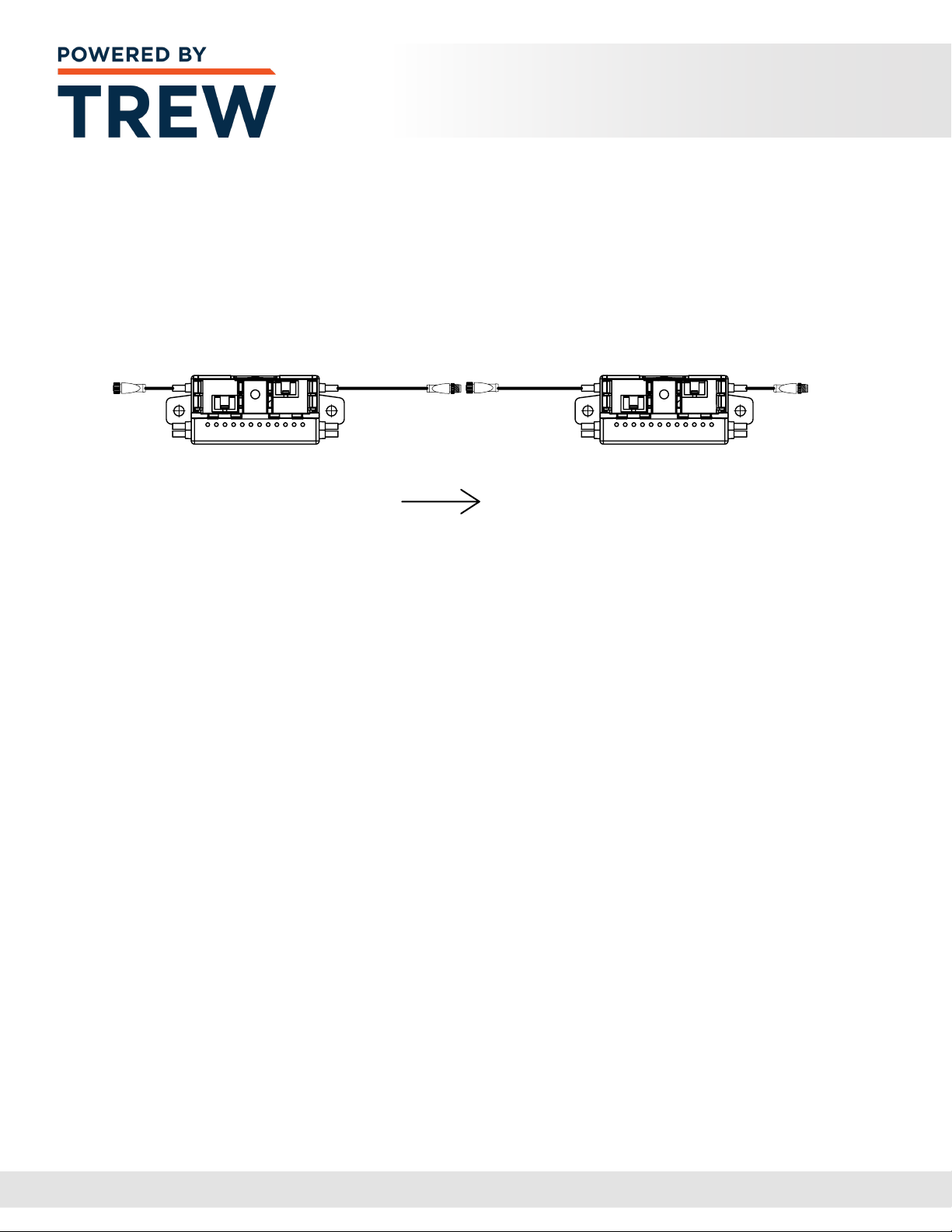
An MDR conveyor with accumulation is composed of several ‘zones’, as shown in the image
below. Each zone is powered by a motorized drive roller (MDR). The MDRs are controlled by
a communications network, allowing the zones to communicate with each other to achieve
the desired accumulation method. The rollers in a zone do not rotate until product has been
detected in the adjacent upstream zone. In other words, the rollers in Zone 2 do not rotate
until the photo eye sensor in Zone 1 detects a product. The rollers in Zone 3 do not rotate
until the photo eye sensor in Zone 2 detects a product.
There are two types of accumulation release: Singulation release and Slug release. Singulation
release allows one product to be released at a time after the downstream zone has cleared.
Slug release allows a predetermined amount of product to be released at one time after the
downstream zone has cleared. Slug release is typically used in Palletizing or Machine loading
conditions. The type of release to be used is usually determined at design time.
Accumulation begins when a product is forced to remain in Zone 4. The photo eye sensor
in Zone 4 detects the product and turns o the motorized drive roller in Zone 4, stopping all
the rollers in that zone. When a second product is detected by the photo eye sensor in Zone
3, the motorized drive roller in Zone 3 is turned o, stopping all the rollers in that zone.
This accumulation sequence is repeated for each succeeding zone as long as the product
in Zone 4 is forced to remain in position.
When the product in Zone 4 can be released, the motorized drive roller is turned on and the
product moves down the conveyor system. When the product clears the photo eye sensor
in Zone 4, the motorized drive roller in Zone 3 is turned on and the product moves from
Zone 3 to Zone 4. This release sequence is repeated for each succeeding zone as long as
product is not intentionally stopped in any given zone. The subsequent gap between products
is approximately equal to one zone length. This accumulation sequence may be started
anywhere along the length of the conveyor.
The MDR accumulation is a true zero--pressure accumulation (ZPA). This means that
the product being conveyed never comes in contact with any other product; provided
it is dimensionally compatible with the zone (product length is less than the zone length).
K1
MOT1
IN1
X1
MOT2
IN2
X2
K1
MOT1
IN1
X1
MOT2
IN2
X2
TO ZONE 2 PHOTOEYE
TO ZONE 2 MOTOR
TO ZONE 4 PHOTOEYE
TO ZONE 4 MOTOR
TO ZONE 3 PHOTOEYE
TO ZONE 3 MOTOR
TO ZONE 1 PHOTOEYE
TO ZONE 1 MOTOR
DOWNSTREAM
CONVEYOR
INTERCONNECTION
UPSTREAM
CONVEYOR
INTERCONNECTION
FLOW

REV A MDR Spiral - Installation and Maintenance Manual
www.poweredbyTrew.com
OVERVIEW 1
1.2
Standard Zones
The image below shows a typical zone layout for a standard intermediate zone.
Each zone has one motorized drive roller (MDR), photo eye sensor, reector,
motor control card, and carrier rollers.

www.poweredbyTrew.com
1.800.571.8739
REV A MDR Spiral - Installation and Maintenance Manual
2
COMPONENTS

REV A MDR Spiral - Installation and Maintenance Manual
www.poweredbyTrew.com
COMPONENTS 2
Motor Control Card - Auto & Full Control
The motor control card provides true zero pressure accumulation and other control options
to a conveyor system. Each motor control card manages the functionality of (2) motorized
drive rollers which in turn drives idler rollers using O-rings or other belts. The ZPA motor
control card, MDR and idler rollers, with associated sensors and switches, are assembled
into a short conveyor section - or zone. A logic-controlled, ZPA conveyor is created when a
number of zones are connected together and a four-wire M12 connector links each motor
control card electronically. The MDRs only operate when a package is present and is detected
by a photo-eye. If the downstream zone is empty, the package moves forward. The motor
control card has several design features allowing the integration of workstations, lifts
and turntables into a conveyor design. If the ZPA motor card is to control only (1) motor
(one zone), the seconed zone logic must be turned o with mode 2 (single).
Changing the Operation of the ZPA
Additional control signals can be sent to the motor control cards by using various I/O signals
on its connectors. The logic is passed from board to board through modular RJ-11 telephone
communication cables. By setting rotary switches (S1, S2, S3), you can change its speed,
direction and operating mode, respectively.
Motor Control Card Circuit Protection
The motor outputs are protected by safety fuses with 5A-rated current. They prevent damage
to the motor control chips from back EMF that might be generated by the MDR when it is
rotated by an outside force such as heavy packages arriving at high speed from powered or
gravity-fed conveyors. This is referred to as “over-driving” the MDR. Care should be taken to
minimize over-driving.
2.1

REV A MDR Spiral - Installation and Maintenance Manual
www.poweredbyTrew.com
COMPONENTS 2
Motor Control Card Replacement
1 Turn o and lock out the power supply to the conveyor
2Remove the auxillary power cable from the card
3Remove the drive roller cable connector and the control cable
or com-link from the drive card
4Remove drive card and mounting bracket from the conveyor
5Remove drive card from mounting bracket and inspect for Red LED
6Inspect the original card and observe the jumper and switch settings
7Set the switches and jumpers on the new card to match the old one
8Replace old drive card with spare drive card
9Carefully connect the control cable or com-link and drive roller cable to the card
10 Reconnect the auxillary power cable to the card
11 Unlock the power supply and turn the conveyor on
Before attempting to repair or replace a drive roller, drive card, controller device, or any other
device connected to these components, be sure that power to the controls is locked out to
prevent premature or accidental start-up. Failure to follow this instruction may result in serious
personal injury, and/or equipment damage.
2.2
Note: Only follow motor card bracket steps if applicable, as motor card
brackets are not used on Intermediate Set High.

REV A MDR Spiral - Installation and Maintenance Manual
www.poweredbyTrew.com
COMPONENTS 2
Motorized Drive Roller (MDR)
The motorized drive roller (MDR) is the muscle of the conveyor zone. It provides the torque
and speed required to move the product to the next zone. The MDR has the motor and
gearing encapsulated inside the roller tube.
Replacement of MDR
1 Turn o and Lockout / Tag-out all power to the conveyor section
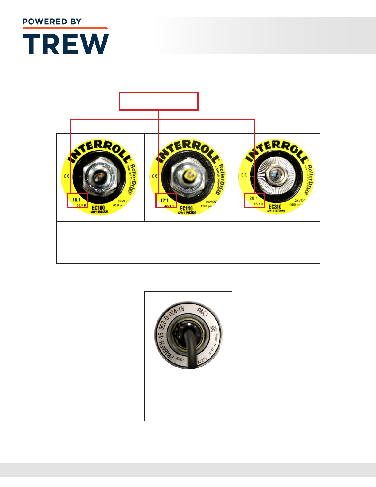
2Make sure that the Gear Ratio matches that of the roller that is being replaced.
Standard Gear Ratios would include: 16:1, 20:1, 24:1, 36:1, 64:1, and 96:1.
This is important if the conveyor system is comprised of more than one speed
3The replacement roller should include:
aMotorized Drive Roller
bHardware Kit
i. star washers – Qty. 2
ii. motor nut
iii. motor instructions
4Install a star washer on the threaded motor shaft
5Insert the MDR connector into the hex hole and gently pull the cable
extending from the motor through
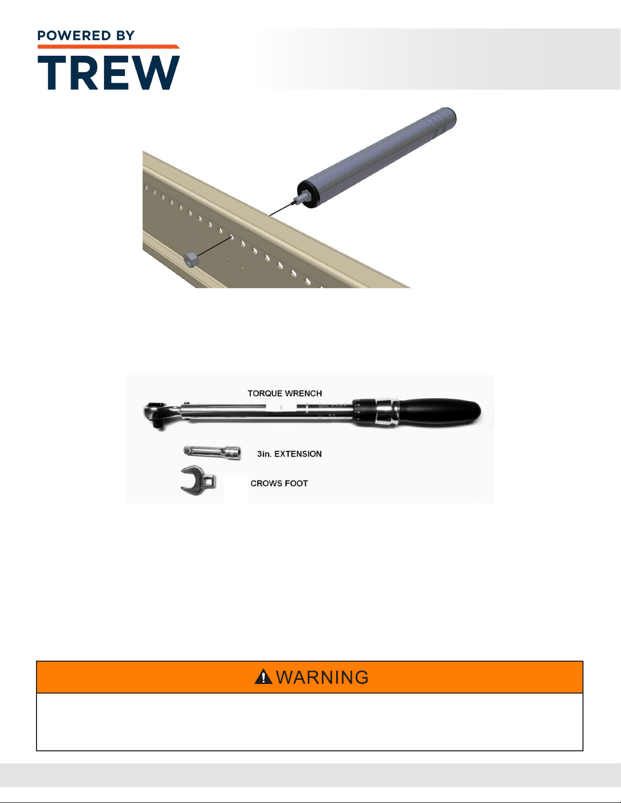
6Insert the threaded hex shaft into the hex hole. Push the spring loaded idler shaft
inwards and line the roller up with the hole. Release the idler shaft and allow
it to pop into the hole in the frame. The image on Page 2.6 shows an exploded
view of the process
7Install the outer star washer
2.3
REV A MDR Spiral - Installation and Maintenance Manual
www.poweredbyTrew.com
COMPONENTS 2
8The motor nut threads on to the motorized drive roller shaft, and should
be to the proper torque of: See Page 2.5 for Proper Torque Information.
9Tools required to achieve proper torque can be seen below
10 Plug the motor cable into the motor control card
11 Turn on power to the conveyor section
12 Check to see if roller operates by passing your hand in front of the photo eye sensor
of the zone that is being serviced or the photo eye sensor located upstream
with respect to ow
13 If the MDR does not operate review the Troubleshooting Section
These checks must be performed with the power to the conveyor section turned “ON”.
Only qualied electricians should be allowed to perform these checks. Failure to follow
this instruction may result in serious personal injury and/or equipment damage.
2.4
REV A MDR Spiral - Installation and Maintenance Manual
www.poweredbyTrew.com
COMPONENTS 2
EC110 and EC100:
30 ft-lbs +/- 5 ft-lbs
(40.7 N-M +/- 6 N-M)
ITOH:
22.5 ft-lbs +/- 5 ft-lbs
(30.5 N-M +/= 6 N-M)
EC310:
50 ft-lbs +/- 5 ft-lbs
(67.8 N-m +/- 6 N-m)
Gear Ratios Vary.
Proper Torque
2.5

REV A MDR Spiral - Installation and Maintenance Manual
www.poweredbyTrew.com
COMPONENTS 2
Carrier Roller
The carrier roller is used to take the weight of the product and also distributes the torque
generated by the motorized drive rollers via o-belts, chain, timing belts, strip belts,
or full-width belts. Generally, no more than nine carrier rollers per motorized drive roller
are used in each zone.
Replacement of Carrier Roller
1 Turn o and Lockout / Tag-out all power to the conveyor section
2Use an appropriate tool to push in the spring loaded axle on the roller
and free that side of the axle from the frame of the conveyor
3Carefully disengage the opposite end of the roller from the frame.
Make sure the axle is not pinched on the frame causing damage during removal
4Remove the disengaged roller entirely from the frame section
5Carefully maneuver the roller to allow the drive belts to be removed
from the grooved end of the roller. Set old roller aside
6 Install new roller by rst maneuvering grooved end through the drive belts,
ensuring the belts are aligned in the appropriate grooves
7Insert the axle of the replacement roller through the conveyor frame
8Use an appropriate tool to push in the spring loaded axle and lower
the roller into position, aligning the axle with the hex hole in the conveyor frame
9Unlock and turn on the power to the conveyor section
2.6

REV A MDR Spiral - Installation and Maintenance Manual
www.poweredbyTrew.com
COMPONENTS 2
Photo Eye Sensor
A photo eye sensor is used to sense the presence of the product. Two styles of photo
eye sensors are used on standard Conveyor: Retro-Reective Photoelectric Sensor
& Background Suppression Diused Photoelectric Sensor.
Replacement of a Photo Eye Sensor
1 Turn o and Lockout / Tag-out all power to the conveyor section
2Locate end of Photo Eye Sensor cable and unplug from the roller drive card
3Carefully remove cable from any holes in conveyor frame.
Note the routing path of the cable
4Remove fasteners from the Photo Eye Sensor mounting bracket
and remove Sensor from conveyor
5Install new Sensor at the same location as the old sensor
6Route the new Sensor cable through the same path as the old sensor cable
7Install Sensor cable plug into the roller drive card
2.7
REV A MDR Spiral - Installation and Maintenance Manual
www.poweredbyTrew.com
COMPONENTS 2
Standard Retro- Reflective Photoelectric Sensor
The image and diagram below displays the cable connection types for the Tru-Vue ML17
series photoelectric sensors - 3.5m sensing range - Polarized retro-reective mode -
PNP Dark-Operated Sensor.
2.8
REV A MDR Spiral - Installation and Maintenance Manual
www.poweredbyTrew.com
COMPONENTS 2
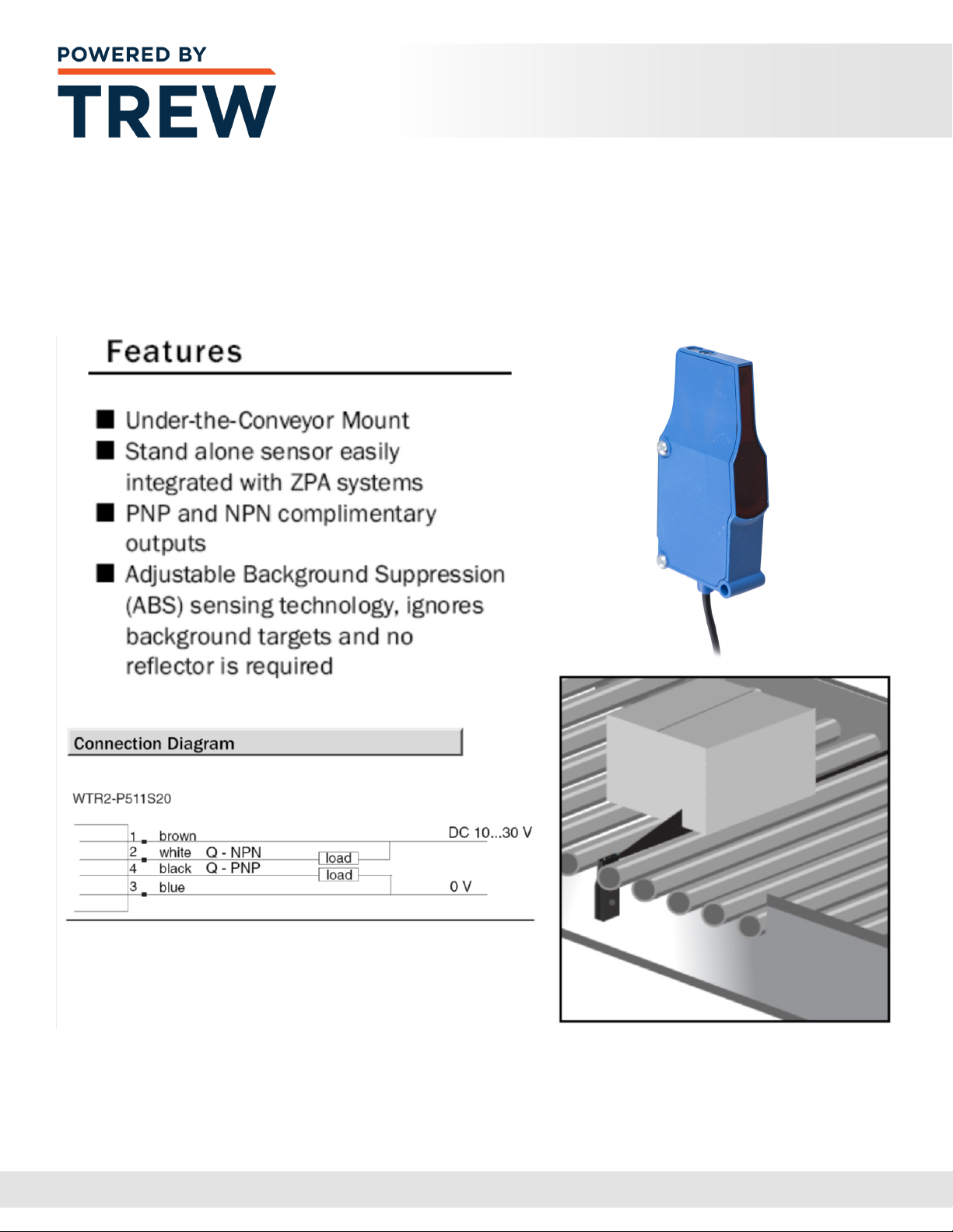
Standard Background Suppression Diffused
Photoelectric Sensor (SICK)
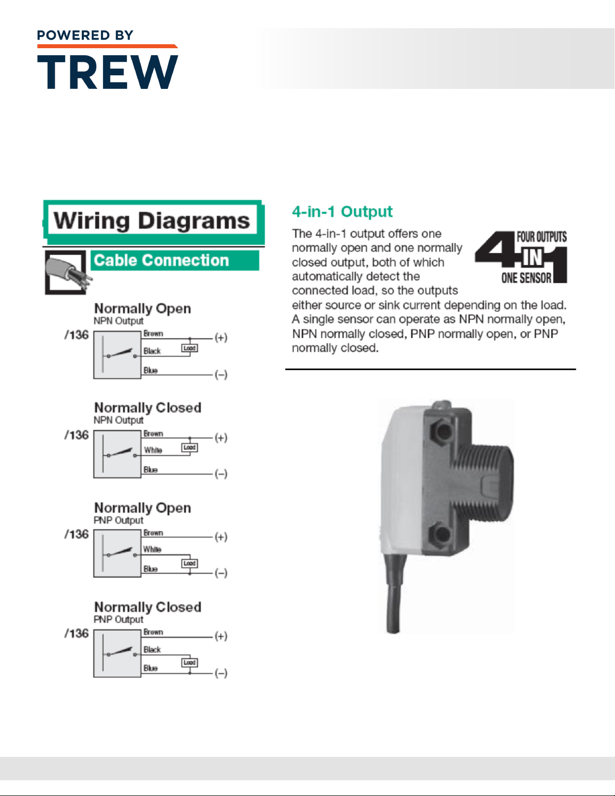
The image and diagram below displays the connection diagram for the WTR series
photoelectric sensors – 90mm sensing range – Background Suppression Diused-4-in-1
output N.O./N.C. - 2m cable.
2.9

REV A MDR Spiral - Installation and Maintenance Manual
www.poweredbyTrew.com
COMPONENTS 2
Drive Belts (O-Bands)
MDR conveyor utilizes drive belts to connect individual rollers together to create a Zone.
The drive belts can be O-bands or V belts, depending upon load and speed requirements
of the conveyor.
Over time the drive belts can exhibit wear. O-bands in particular can wear or stretch,
eventually allowing excessive slippage in the roller groove. When this happens,
the rollers in the zones may not rotate and inadequately convey packages.
Replacement of O-bands is quick and easy.
Replacement of O-Bands
1 Remove the roller having the aected O-band, following procedures
for roller removal discussed earlier in this manual
2 Remove the (2) adjacent rollers. At this point, the aected O-band can be removed
3Place new O-bands over the grooved end of the roller(s)
and re-install the rollers
2.10

www.poweredbyTrew.com
1.800.571.8739
REV A MDR Spiral - Installation and Maintenance Manual
3
PREVENTATIVE
MAINTENANCE

REV A MDR Spiral - Installation and Maintenance Manual
www.poweredbyTrew.com
PREVENTATIVE MAINTENANCE 3
The satisfactory performance and reliability of this equipment is dependent upon a procient
preventive maintenance (PM) program with scheduled equipment inspections under normal
operating conditions.
Accurate records of maintenance and repairs will help to identify problem areas and
repetitive problem patterns. It is imperative that adequate records be kept in connection
with the preventive maintenance program. These records should contain the date of
inspection, inspection results, equipment services, repair history, part replacement history,
and any other information that will help to make maintenance process more ecient and
accurate. It is recommended that each conveyor have its own record. Properly kept, the
conveyor record sheet will form a mechanical history of the equipment covered.
Preventive maintenance consists of regular service (lubrication, adjustments, cleaning, etc.).
In addition, it consists of ”keeping your eyes, ears, and nose open.” Use your eyes to see
potential component failure. Use your ears to listen for abnormal or louder than normal noises.
Use your nose to smell a motor running abnormally warm in time to prevent its burnout.
These sights, noises, and smells can be indicators of lack of lubrication, misalignment,
or other potential trouble. Ignore them and you will be replacing a shaft, motor, or whatever
does go out when a component is lacking proper preventive maintenance.
Only qualied maintenance specialists should maintain the mechanical, electrical and
pneumatic portion of the conveyor.
3.1
Before performing any maintenance or lubrication services, follow
the lockout/tagout procedure in the Safety section to ensure that the
equipment is safe to work on. Failure to follow this instruction may
result in serious personal injury and/or equipment damage.

REV A MDR Spiral - Installation and Maintenance Manual
www.poweredbyTrew.com
PREVENTATIVE MAINTENANCE 3
Maintenance Precautions
1When testing operating performance, do not start the equipment until all operations
and maintenance personnel are notied and clear of the unit being tested
2Be certain that required safety guards are never removed without authorization
3Never run the equipment under production conditions without safety guards in place
4Do not make any equipment repairs, while the conveyor is running
5Keep hands, hair and clothing clear of any moving parts
6Never attempt to clear load jams, while equipment is running
7Always use appropriate tools when making repairs or adjustments
8Observe all warning labels and follow plant safety rules
9Make sure all connectors are secure and all wires are free from interference,
obstruction, and any moving parts
Cleaning and Inspection
Generally, there are many reasons for cleaning:
1To allow heat to dissipate (motors and gearboxes)
2To prevent wear on moving parts
3To prevent binding
4For proper operation
5Operating personnel will most likely treat clean equipment with more care
3.2
You must read and understand these precautions completely before operating, setting up,
running, or performing maintenance on the equipment. Failure to follow this instruction may
result in serious personal injury and/or equipment damage.

REV A MDR Spiral - Installation and Maintenance Manual
www.poweredbyTrew.com
PREVENTATIVE MAINTENANCE 3
Any prescribed cleaning schedule should be modied as experience is gained. A thorough
inspection should be performed while cleaning problem areas.
The total value of inspection procedures is determined largely by the consistency and
regularity of the schedule. A denite interval of inspection must be established and obeyed.
This is usually easier to accomplish if a ”round robin” system of inspection is used. It is
recommended that a general inspection that will ensure a thorough examination of each
component and assembly contained in the system be done at least once for each thirty
day period of operation. Results of these general inspections should be documented
in the conveyor record of the unit inspected.
The probability of mechanical/electrical problems increase during periods of heavy usage,
so an additional inspection immediately before and after a these periods is recommended.
Daily Inspection
Walk the entire length of conveyor system and observe the following:
1With the conveyor running, listen for abnormal noises that could indicate:
• Worn bearings in rollers, motors, reducers, etc.
• O-Belt making contact due to misalignment or improper adjustment
2With the conveyor shut down, look for the following:
• Strings or other foreign material wrapped around bearings,
shafts, or rollers. Remove all foreign material immediately
• Shavings or belt dust under conveyor that would indicate misaligned
or damaged components
• Oil leakage that would indicate faulty bearings or seals in rollers,
motors, reducers, etc.
3Check pneumatic regulators for proper setting and listen for air leaks
3.3
Other manuals for 1500 Series
1
Table of contents
Other TREW Accessories manuals


