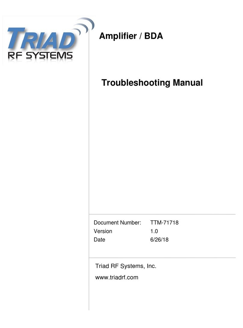
Triad RF Systems Microhard IPnDDL Use and care manual

Document Number TIM-61818
Version 1.0
Date 06/18/2018
Triad RF Systems Confidential
Microhard IPnDDL – Triad RF Systems BDA
Integration Manual
Triad RF Systems, Inc.
11 Harts Ln Suite i
East Brunswick, NJ 08816

Triad RF Systems, Inc. Confidential Page i
Notice
Triad RF Systems reserves the right to make changes to its products or discontinue any
of its products or offerings without notice.
Triad warrants the performance of its products to the specifications applicable at the time
of sale in accordance with Triad’s standard warranty.
Revision History
Version Date Changes Author
1.0 6/28/18 Draft Document - Initial Release CFD

Triad RF Systems, Inc. Confidential Page ii
TableofContents
1.Overview....................................................................................................................3
2.Initial Radio Configuration..........................................................................................4
2.1Radio Output Power .........................................................................................4
2.2Frequency.........................................................................................................4
2.3Data Link Distance ...........................................................................................4
3.DC and RF Connections............................................................................................5
3.1Wiring Harness – MicroHard IPnDDL...............................................................5
3.2RF Connections................................................................................................6
4.Troubleshooting.........................................................................................................7

Triad RF Systems, Inc. Confidential Page 3
1. Overview
This document details the integration and setup of a MicroHard IPnDDL data link radio with a
compatible Triad RF Systems Bi-Directional Amplifier. This will include instructions for wiring
connections as well as initial and ideal radio settings to maximize data link performance.
The MicroHard IPnDDL radio is used in a variety of military and commercial applications. Some
of the applications in which these radios are used may present difficult RF or physical
environment conditions.
Certain custom-designed products may have been supplied with a different set of operating
manuals or interface control documents. In those cases, the recommendations of the
documents supplied supersede the ones contained in this manual.
The instructions provided here will require a copy of the Triad RF Systems BDA specification
sheet, which can be obtained from our website at www.triadrf.com. For additional assistance
Notes that accompany the warning symbol denote instructions and
guidelines that must be followed. Failure to follow these guidelines may
result in damage to the amplifier that is not covered by Triad’s product
warranty.

Triad RF Systems, Inc. Confidential Page 4
2. Initial Radio Configuration
Below is an outline of recommended settings for the MicroHard IPnDDL, to be set prior to
connecting to the Triad RF Systems BDA.
2.1 Radio Output Power
Please be sure to terminate the RF ports on the radio before powering on the radio.
It is recommended to initially set the radio output power to its minimum value. This will
prevent any potential damage to the Triad BDA. The ideal radio power will depend on
several factors such as: amplifier gain, data rate required, and amplifier output power.
Consult the Triad BDA specification sheet for linear power output.
2.2 Frequency
Set the radio operating frequency within the range of the Triad BDA frequency range.
Consult specification sheet for frequency details.
2.3 Data Link Distance
Set the data link distance to desired or expected operating distance.
Before powering on the radio, ensure that the RF ports are properly
terminated, or connected to their antennae. Operating the unit with the RF
ports open can cause damage to the radio.

Triad RF Systems, Inc. Confidential Page 5
3. DC and RF Connections
A brief outline of electrical and RF connections of the devices under test are listed in the sub-
sections below. Be sure to inspect both wire harnesses and connectors for damage or debris
before connecting.
3.1 Wiring Harness – MicroHard IPnDDL
Note: To ensure compatibility with the MicroHard IPnDDL, the compatible Triad RF Systems
BDA has been configured with Automatic Tx/Rx switching. Therefore no electrical connection
between the IPnDDL and Triad BDA will be necessary.
Please consult the Triad BDA specification sheet for wiring harness pinout.

Triad RF Systems, Inc. Confidential Page 6
3.2 RF Connections
Below is a visual representation of the IPnDDL and Triad BDA RF Connections, as well as a
table of the required connections between the IPnDDL, Triad BDA, and Antennae.
MicroHard IPnDDL Connect to Triad BDA
ANTENNA
RADIO
Visual representation only. Please consult specification sheet for RF connections
Triad BDA Connect to Your Equipment
ANTENNA
Antenna
Triad RF products are unconditionally stable and can operate into an open
circuit up to a certain power output level. Refer to the specification sheet for
those limits. However, it is good practice to avoid operating the amplifier into
an open circuit for an extended period of time.

Triad RF Systems, Inc. Confidential Page 7
4. Troubleshooting
The table below will outline common setup issues as well as suggested troubleshooting
methods.
The instructions provided here will require a copy of the product’s specification sheet, which can
be obtained from our website at www.triadrf.com
SymptomPossibleCauseSolution
BDA will not turn on
when voltage is
applied
Connector Wiring Ensure proper connections are made to wiring
harness.
Consult wiring diagram on product's spec sheet
Supply Voltage Range
Exceeded
Ensure power supply output is set to acceptable
voltage range.
Consult spec sheet for operating voltage range
Power Supply Current
Insufficient
Ensure power supply is capable of supplying at least
1.5x the expected current draw of the amplifier. This
is due to the inrush current of the unit as it powers
on
BDA powers down
after some time,
then turns back on
shortly after
Over-Temperature
Protection being
triggered. Amplifier
exceeding
recommended operating
temperature
Ensure sufficient heatsinking has been applied to
unit. Add or increase airflow to heatsink
Intermittent or non-
existent data link
Improper wiring harness
connections
Refer to section 3.1 and verify that the proper
connections have been made between the SC4200
and Triad BDA wiring harnesses
Improper RF
connections
Refer to section 3.2 and verify that the proper RF
connections have been made between the SC4200
and Triad BDA
Data rate slower
than desired. Excess radio output
power - EVM too high Reduce radio output power in 0.5 dB steps until data
rate improves.
For continuing issues, or to request any clarifications or additions to this document, please
contact [email protected]
Table of contents
Other Triad RF Systems Amplifier manuals
Popular Amplifier manuals by other brands
OSD Audio
OSD Audio AMP120 owner's manual

Hughes & Kettner
Hughes & Kettner Tour Reverb manual
moon
moon Neo Series 220i owner's manual
Hypex Electronics
Hypex Electronics UcD400 Stereo kit Getting started

Marshall Amplification
Marshall Amplification 1923 owner's manual
Pro-Ject Audio Systems
Pro-Ject Audio Systems Box RS Instructions for use

Beresford
Beresford Capella Owner reference manual

Master audio
Master audio SM1000 user manual
Extron electronics
Extron electronics XTRA FULL RACK XPA 2002 Setup guide
Yamaha
Yamaha AX-596 Service manual
Audio Research
Audio Research Reference 3 owner's manual
RCA
RCA VH100 - VH 100 - RF Amplifier user manual
