Alewings UniPower2B Parts list manual

Alewings ®
di Alessandro Torri
v. del Lavoro, 41 20084 Lacchiarella MI ITALY
www.alewings.it [email protected]
V1.1
Cod. 90010601
This doesn’t happen anymore with UniPower2B: with only 2 batteries it generates independent outputs for supplying all on board
devices. And, what is more, it extends the safety of 2 batteries system to all utilities on board, included engine or turbine supplying.
Thanks to 2 batteries and double electronic circuits, if one branch of power supplying doesn’t work anymore, all outputs will continue to work
normally.
You can use different type of batteries (ATTENTION: always 2 identical each other):
- 2 batteries Li.Poli 7,4V 2S
- 2 batteries Li.Fe 6,6V 2S
- 2 batteries Nixx 6V 5S
You can choose among three modalities of managing batteries:
- single battery (when you want to use only one battery renouncing to redundancy)
- 2 batteries discharging at the same time
- 2 batteries, a main one and a reserve one: the second battery will be used only if main one is discharged or disconnected.
You can also choose the type of motor to be supplied: gasoline engine or turbine.
UniPower generates 3 independent outputs:
- First one for supplying receiver and servos. You can choose the output voltage from 5V to 7,4V by rotating the potentiometer on the
device with a small screwdriver.
- Second one, not stabilized, exclusively dedicated to supplying the engine/turbine.
- Third one, not stabilized, presents 3 independent lines which can supply 3 devices such as smoke pump, lights, gears, brakes; each line is
protected by a 10A fuse.
Turning on/off is by a button while two light indicators allow you to check the batteries status of charge. Button and light indicators are on the
device, but you can remote them on the outside of your model using the optional external panel (item 90010701, separately sold). UniPower
is provided with MPX connectors and all accessories for mounting included.
Dear customer,
thanks for choosing an Alewings product.
Medium or big airplanes, both jet and acro, in most cases have
many batteries on board: typically 2 for receiver and servos, 1 for
engine or turbine and others smaller for smokes, landing gears and
electric brakes, lights ecc.. So you have from a minimum of 3 to a
maximum of 6 battery packs on your model and redundancy only
for receiver and servos.
UniPower series supplying units are a total innovation developed
by Alewings and represent a new concept of on board supplying.
Power supply unit
UniPower2B
Battery 1
input
Battery 2
input
NOT stabilized
output
3 NOT stabilized
outputs
Battery
voltage
monitor
USAGE MANUAL
Start
button
Stabilized output
5 - 7.4V 30A

Place the 4 vibration dampeners provided into the appropriate holes on the base of the device.
Position the 4 screws into the dampeners and fix the device to the plate on your model. ATTENTION: tighten screws until screw head reaches
the dampener, not more. Not tighten too much, not push the dampeners.
It is suggested to realize an anti vibration holder using small grommet columns in order to isolate the electronic circuit from vibrations and to
allow air to circulate between base of the device and model plate.
If you decide to fix UniPower directly to the plate without small columns you must open holes in correspondence of heat sink and air intakes of
the device so that they can facilitate cooling.
FIXING
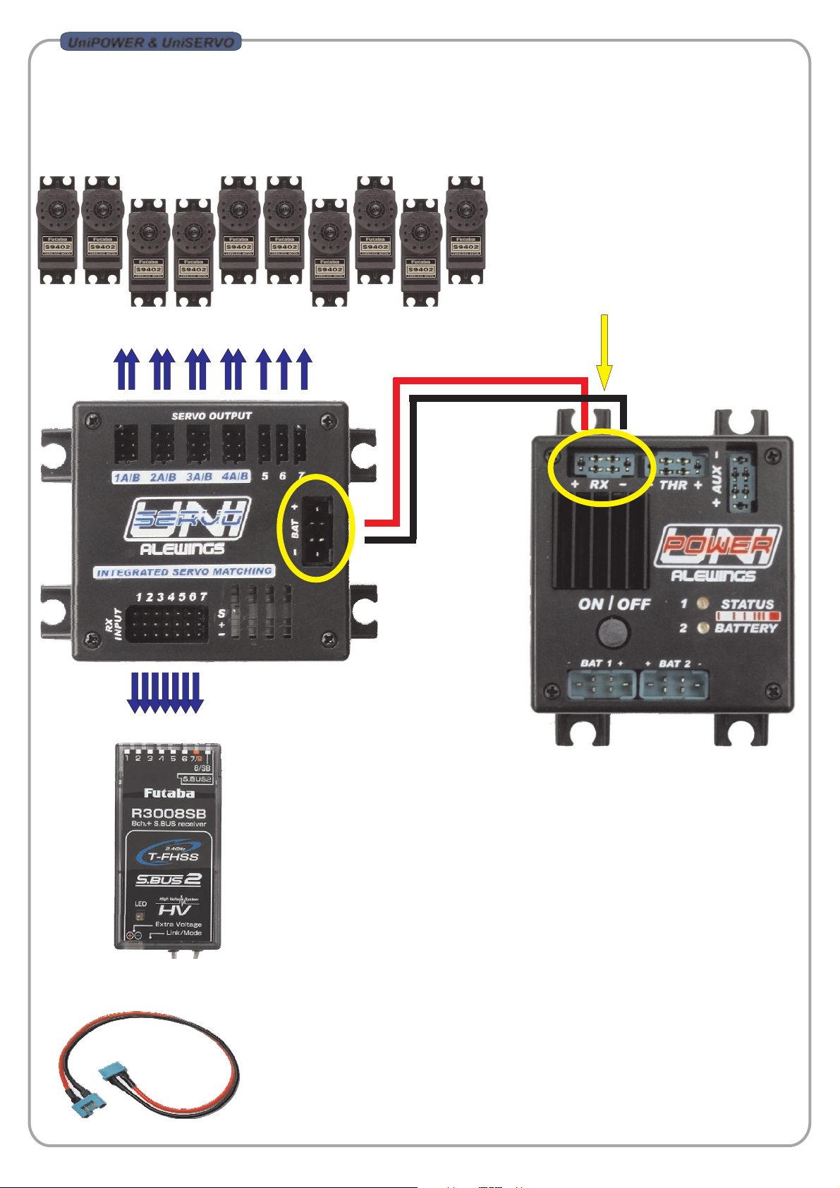
Before using UniPower, please configure the device modality better fitting your need referring to “Programming” paragraph. Connect the
device as shown into the paragraph “Connection” and set, on the back side of the device, the correct output voltage for your receiver and
servos.
Connect batteries to inputs Battery 1 and Battery 2. Push and keep pushed the button for at least 2 seconds; when light indicators light up,
release the button.
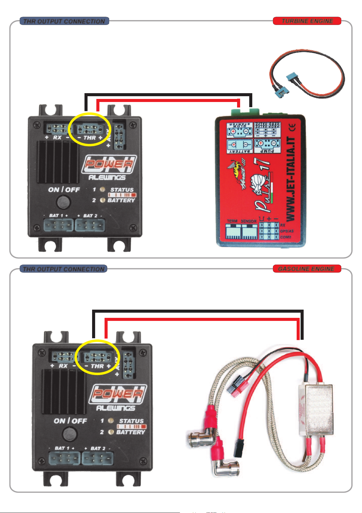
When turned on the device automatically activates the 3 outputs; “RX” outputs is activated immediately, “THR” and “AUX” are activated after 3
seconds. This interval of time allows the receiver to be activated before motor and auxiliary devices are supplied.
After this time light indicators start to flash; the frequency of flashes indicates the battery status; if one of batteries is low or not connected, the
corresponding led will be steady on (see “Battery status” paragraph).
With the device turned on, push and keep pushed the button for at least 2 seconds.
As soon as you push the button the light indicators will light up steady and after 2 seconds they will turn off. Release the button: the device is off
and automatically deactivates the 3 outputs.
The “RX” output is deactivated immediately; “THR” and “AUX” outputs are deactivated immediately only if you set the motor type as “Gasoline
engine”.
If you set the motor type as “Turbine”, “THR” and “AUX” outputs will be deactivated after 3 minutes; so the receiver can be switched off while
ECU is still supplied for finishing the cooling process.
Please note: before turning the device off or after a flight session, is always recommended to check the batteries status as the system keeps
memory of the minimum value of battery charge recorded during the session. If you turn the device off, this value is reset.
TURNING ON:
TURNING OFF:
ATTENTION: if you don’t use UniPower for more than one week, please disconnect batteries.
USAGE
Li.Poli battery 2s 7,4V:
Li.Fe battery 2S 6,6V:
Nixx battery 5S 6,0V:
- 1 flash every 2seconds: >7,5V
- 1 flash every second: >7,2V
- 1 flash every 0,5 seconds: >7,0V
- Light solid: <7,0V and loss of power supplying
- 1 flash every 2seconds: >6,4V
- 1 flash every second: >5,9V
- 1 flash every 0,5 seconds: >5,7V
- Light solid: <5,7V and loss of power supplying
- 1 flash every 2seconds: >6,3V
- 1 flash every second: >6,1V
- 1 flash every 0,5 seconds: >6,0V
- Light solid: <6,0V and loss of power supplying
Two seconds after turning on, the device starts to check batteries status. Light indicators flash to indicate batteries residual charge: more
the flashes are rapid less is the residual charge of the batteries.
If you want to reset the alarm, you have to turn the device off and on again. If the alarm remains, please check connections and measure
batteries charge.
ATTENTION: if light indicators are steady on, don’t use the device.
ATTENTION: the flashes of the indicator lights don't correspond to the instantaneous voltage of the batteries but to the minimum
voltage detected when you turned the device on.
STATUS BATTERY
Battery 1 status
indicator
Battery 2 status
indicator

You can use UniPower also together with servos managing unit UniSERVO7ADJ. See the connection scheme below.
For connecting UniPower to UniServo please use a black/red cable of adequate section (min 1,5 sqmm) with male and female MPX
connectors.
TO SERVOS
TO RECEIVER
Cavi batteria per collegamento UniPower - UniServo disponibili a catalogo e forniti separatamente da UniPower e UniServo.
Cod.90050322 Cavo prolunga batteria MPX M-F 2x1.5mmq L150mm
Cod.90050323 Cavo prolunga batteria MPX M-F 2x2.5mmq L150mm
Cod.90050324 Cavo prolunga batteria MPX M-F 2x1.5mmq L300mm
Cod.90050325 Cavo prolunga batteria MPX M-F 2x2.5mmq L300mm
UniPOWER & UniSERVO
“RX” Output
Adjustable output
voltage from 5V to 7.4V
Output current
up to 30A peak
Please see “Cables and
connectors” section on
www.alewings.com in order to
find a connection cable
UniPower-receiver suitable for
your needs.

SETTING VOLTAGE FOR “RX” OUTPUT
“Rx” output supplies receiver and servos; verify which is the correct voltage for your own receiver and servos.
Rotate, with the aid of a little screwdriver, the potentiometer and choose the position corresponding to the desired voltage. If you want to
set a voltage lying between values indicated or with a precision to one tenth of a volt, you are suggested to use a voltmeter in order to see
the output voltage while setting.
Position the voltmeter tips on positive and negative poles of “RX” output connector and rotate the potentiometer: you will be able to set
the voltage with maximum precision.
5V
7.4V
6.2V
5.5V
7.0V
SETTING RX VOLTAGE
ATTENTION: YOU MUST SET THE RIGHT OUTPUT VOLTAGE BEFORE
CONNECTING UNIPOWER TO ANY DEVICE YOU WANT TO SUPPLY.
RX OUTPUT CONNECTION
OR
You can use UniPower for direct supplying of receiver; it is possible to use also receiver with double battery input. You need a black/red
cable of adequate section (min 1,5 sqmm) with male MPX connector for connection to UniPower “RX” outputs and, on the other side, a
suitable connector for connection to your receiver.
“RX” Output
Adjustable output voltage from 5V to 7.4V
Output current up to 30A peak
SETTING VOLTAGE
FOR “RX” OUTPUT
Please see “Cables and
connectors” section on
www.alewings.con in order to
find a connection cable
UniPower-receiver suitable for
your needs.

UniPower supplying Engine Control Unit for turbine.
Please connect UniPower “THR” output to battery input on the ECU. You are suggested to use a black/red cable of adequate section (min 4
sqmm) with male and female MPX connectors.
- Item 90050342: Battery extension lead with male and female MPX connector 2x6 sqmm Lenght 150mm
- Item 90050343: Battery extension lead with male and female MPX connector 2x6 sqmm Lenght 300mm
UniPower supplying spark ignition for gasoline engine.
Please connect UniPower “THR” output to battery input on your spark ignition unit. You are suggested to use a black/red cable of adequate
section (min 1 sqmm).
TURBINE ENGINE
GASOLINE ENGINE
THR OUTPUT CONNECTION
Please see “Cables and
connectors” section on
www.alewings.con in
order to find a
connection cable
UniPower-ECU suitable
for your needs.
THR OUTPUT CONNECTION

AUX 2
AUX 1 AUX 3
GND
GND
GND
10A FUSE
10A
“AUX” OUTPUT CONNECTOR TOP VIEW
Connect all other auxiliary devices you want to supply to 3 “AUX” outputs: lights, smoke pump, retract landing gears, electronic brakes,
starters for smokes.
Use the cable provided and pay maximum attention before connecting since outputs are protected by 10A fuses.
CONNESSIONE USCITE AUX
10A
AUX2 10A
SMOKE PUMP
AUX3 10A
LIGHT NAVIGATOR
AUX1 10A
LANDING GEAR AND BRAKE
10A
10A
10A
10A
10A FUSE
10A FUSE

UniPower comes with the following default setting:
- Modality of managing batteries: double batteries, Battery 1 and Battery 2 discharge simultaneously balancing their charge
- Type of batteries: 7,4V 2S Li.Poly
- Type of motor: gasoline engine
Before starting use you are always suggested to check settings; please proceed as follows:
With the device not powered (both batteries must be disconnected), push and keep pushed ON/OFF button and at the same time connect
one of two batteries.
The two light indicators on the device will start to flash cyclically indicating the current setting; see the following table for correspondence
between flashes and setting:
LED 1 LED 2
Modality of managing batteries (BAT 1 e BAT2)
1 flash 1 flash Single battery
1 flash 2 flash Double battery DEFAULT
1 flash 3 flash Main batteryand backup battery
Type of batteries (BAT 1 e BAT2)
2 flash 1 flash 5 cells Nixx
2 flash 2 flash 2 cells Li.Poli DEFAULT
2 flash 4 flash 2 cells Li.Fe
Type of motor to be supplied
3 flash 1 flash Gasoline engine DEFAULT
3 flash 2 flash Turbine
If setting is right for your needs, disconnect battery so turning the device off and connect again; UniPower is ready to be used. Otherwise, if
you want to change settings, see “Programming” paragraph.
DEFAUL SETTING
After checking the saved settings as shown into “Default setting” paragraph, enter the programming menu to change them.
Programming menu is structured in a sequential way: any time you enter the menu, you have to repeat all steps for saving new data properly.
With the device not powered (i.e. with both batteries disconnected), push and keep pushed ON/OFF button and simultaneously connect one
of two batteries.
The two light indicators on the device will start to flash cyclically indicating the current setting ; after the first cycle of flashes you can enter the
programming menu by pushing ON/OFF button.
The menu is structured in three steps: for each you have to make your choice before proceeding to the following one.
The first LED indicates the parameter you are going to set, the second the possible choices for that parameter. The second LED repeats twice
each sequence of flashes so that you are able to see the number of flashes and then to confirm your choice while the same number of
flashes is repeated.
The device starts a sequence of flashes which refers to step one (see table below); to confirm your choice push button when LED are flashing
according to the desired setting.
LED 1 LED 2
1) Modality of managing batteries (BAT 1 e BAT2)
1 flash 1 flash Single battery
1 flash 2 flash Double battery
1 flash 3 flash Main battery and backup battery
2) Type of batteries (BAT 1 e BAT2)
2 flash 1 flash 5 cells Nixx
2 flash 2 flash 2 cells Li.Poli
2 flash 4 flash 2 cells Li.Fe
3)Type of motor to be supplied
3 flash 1 flash Gasoline engine
3 flash 2 flash Turbine
After you made your choice relatively to third step, the device saves data and automatically turns off; press ON/OFF button to turn it on again.
Disconnect batteries and connect again; UniPower is now ready for use.
PROGRAMMING

SPECIFICHE
EXTERNAL PANEL
Unscrew the 4 screws indicated
and remove the cover
Plug where you must
connect the flat cable of
external panel Plug flat cable pressing
vertically
Reposition the cover and
fix it with its screws
You can buy the optional external panel (Item 90010701) in order to remote ON/OFF button and light indicators outside the model.
For mounting external panel see following instructions:
This is not a toy.
Pay close attention to the following points, as the non
observance of them can destroy the product, nullify your
warranty and lead to property damages or personal severe
injuries!
- Never leave the product unattended while it is switched on, in
use or connected with a power supply. If a defect occurs, it
could set fire to the product or to the surroundings.
- Avoid incorrect connections or connections with reversed
polarity.
- All wires and connections have to be well insulated. Short-
circuits might destroy the product.
- Never allow this product or other electronic components to
come into contact with water, oil, fuels or other conductor liquids,
as these could contain minerals, which are harmful for electronic
circuits. If this happens, stop the use of your product immediately
and let it dry carefully.
- Always wire up all the parts of the equipment carefully. If any of
the connections loosens, due to vibrations, you might damage
your device.
- Never cut off or modify the original plugs
- Never change the polarity of the receiver connectors
- Do not open the product and never solder on the PCB
WARNING
Dimensions: 80x61x23mm
Weight: 65gr without cables
Input voltage: from 6,0V to 8,4V
Batteries: 2x LiPoli 2s - LiFe 2s - Nixx 5s
Output voltage for RX output: from 5,0V to 7,4V stabilized
Max current for RX output: 30A di peak
Output voltage for THR output: not stabilized (the same as battery)
Max current for THR output: 25A continuous
Output voltage for AUX output: AUX 1,2,3 non stabilized
(the same as battery)
Max current for AUX output: 10A
Max current drain: about 30mA with LED lighted
Current drain when OFF: 100uAh about 500mA in 6 months of use
Working temperature: -10 up to +60 °C
Specifications may change without notice.
At the end of its life cycle this product is subject to special
waste disposal and it cannot be disposed with urban
waste
WASTE DISPOSAL
Table of contents
Other Alewings Power Supply manuals
Popular Power Supply manuals by other brands

LST
LST NTM2408-1 Specifications

StarTech.com
StarTech.com ATX2POW400HS instruction manual

Rockwell Automation
Rockwell Automation Allen-Bradley SensaGuard 440N-Z21 Series installation instructions

Eaton
Eaton MTL 9491-PS instruction manual

roal
roal RCB600 user manual

Gigabyte
Gigabyte ODIN Plus 500W user guide