manuals.online logo
Brands
  1. Home
  2. •
  3. Brands
  4. •
  5. TriangleTube
  6. •
  7. Gas Heater
  8. •
  9. TriangleTube CHALLENGER CC 85 User manual

TriangleTube CHALLENGER CC 85 User manual

CHALLENGER
Natural Gas to Propane Instructions
Kit Part Number: CCRKIT64
Kit Includes:
-Rating Label
-Conversion Label
-(4) Propane Gas Orifices
-T-15 Torx Wrench
Recommended Tools:
-Phillips-Head Screwdriver
-Standard Adjustable Wrenches
-Calibrated Combustion Analyzer
Indicates a potentially hazardous situation which, if
ignored, can result in serious injury or substantial
property damage.
Indicates special instructions on installation, operation
or maintenance, which are important to equipment but
not related to personal injury hazards.
WARNING NOTICE
This conversion kit shall be installed by a qualified ser-
vice agency in accordance with the manufacturer’s
instructions and all applicable codes and requirements
of the authority having jurisdiction. If the information in
these instructions is not followed exactly, a fire, an explo-
sion or production of carbon monoxide may result caus-
ing property damage, personal injury or loss of life. The
qualified service agency is responsible for the proper
installation of this kit. This installation is not proper and
complete until the operation of the converted appliance
is checked as specified in the manufacturer’s instruc-
tions supplied with the kit.
Failure to follow instructions below can result in severe
personal injury or damage if ignored:
-Instructions are for a qualified installer / service
technician.
-Read all instructions before proceeding.
-Follow instructions in the proper order.
The gas supply shall be shut off prior to disconnecting
the electrical power, before proceeding with the conver-
sion.
For your safety, turn off electrical power supply at ser-
vice panel and allow appliance to cool before proceeding.
Failure to do so can cause severe personal injury or
death.
Upon completion of the conversion from Natural Gas to
Propane, affix the new rating label included in the kit to
the appliance just below the existing rating label on the
right side jacket panel. DO NOT affix the new label over
the existing rating label. Add propane conversion labeling
to the gas valve. Complete the Installation Record by
recording the combustion readings in the Challenger
Installation and Maintenance Manual.
WARNING
WARNING
CAUTION
WARNING
NOTICE
1
Installation of the Propane Gas Orifice
1. Close the manual gas shut off valve to the appli-
ance.
2. Turn off the electrical power supply to the appliance.
3. Remove the front panel by flipping down the control
panel and loosening the two Phillips head mounting
screw(s) at the control panel. Pull bottom of front
panel forward to remove.
4. Disconnect the gas piping inside the CHALLENGER
enclosure at the brass union located above the gas
valve, and rotate piping towards the back of appli-
ance, see Fig. 1.
The gas orifice is installed in a O-ring gasket. This O-ring
gasket must be reinstalled when ever the gas orifice is
changed. Use care not to damage the O-ring gasket.
5. Separate the O-ring gasket from the natural gas ori-
fice and insert the appropriate brass propane orifice
from Table 1 into the O-ring gasket.
The CHALLENGER appliances contain a natural gas ori-
fice. This orifice must be removed prior to the installation
of the propane orifice.
Failure to retain the O-ring gasket on the gas orifice will cause an
improper seal between the gas valve and the union resulting in a
potential risk of a gas leak. Ensure unions at top and bottom of
gas valve are tight. Any potential gas leakage may result in
death, serious injury or substantial property damage.
Ensure the proper orifice for propane is installed as given in
Table 1. Failure to comply will affect input rate and combus-
tion efficiency of the appliance which may result in death,
serious injury or substantial property damage.
6. nstall proper propane gas orifice/O-ring gasket
assembly on the top of the gas valve.
7. Reconnect the gas piping on top of gas valve and
tighten the brass union connections at the gas valve.
NOTICE
NOTICE
WARNING
WARNING
Gas Orifice
O-Ring Gasket
Gas
Piping
Union
Nut
Gas
Valve
CHALLENGER
Natural Gas to Propane Instructions
2
Fig. 1: CHALLENGER Gas Valve/Orifice
Assembly
Table 1: Propane Gas Orifice
CHALLENGER
MODEL
Propane Gas
Orifice Size
Orifice
Markin
CC50s 0.130” [3.30 mm] 330
CC85 or
CC85s 0.199” [5.05 mm] 505
CC105 or
CC105s 0.199” [5.05 mm] 505
CC125, CC125c or
CC125s 0.220” [5.60 mm] -580-
CC125H or
CC125Hs 0.181” [4.60 mm] 460
CC150s 0.220” [5.60 mm] -580-
8. Open the manual gas shut off valve. Before placing
the CHALLENGER back into operation check and
test all gas connections for leaks. Repair leaks if
found.
Do not check for gas leaks with an open flame. Use a bub-
ble test. Failure to check for gas leaks can cause severe
personal injury, death or substantial property damage.
Inspect Ignition Electrode
Inspection of the ignition electrode is not required on a
brand new previously unfired CHALLENGER unless after
completing the gas conversion, ignition issues are pre-
sent. Verify smooth ignition performance after complet-
ing the gas conversion to determine if the electrode may
require inspection.
Prior to inspecting the ignition electrode, ensure all electri-
cal power supply to the appliance is turned off to avoid elec-
trical shock.
1. Remove the ignition electrode using the T-15 Torx
wrench.
2. Remove any white oxides accumulated on the elec-
trode using fine grit sandpaper or steel wool. f the
electrode does not clean to a satisfactory condition,
replace the ignitor.
3. Check igniter to Fig. 2
4. When replacing the ignition electrode, ensure the
gasket is in good condition and correctly positioned,
replace gasket if necessary.
Check Inlet Gas Supply Pressure
1. Turn on the electrical power supply to the CHAL-
LENGER.
2. Check the inlet gas supply pressure to the CHAL-
LENGER at the gas valve see Figs. 3 & 4. Ensure a
minimum pressure of 5” w.c [13 mbar] during flow con-
ditions with all gas appliances firing including the
CHALLENGER and a maximum pressure of 13” w.c
[32 mbar] during non-flow conditions with all gas appli-
ances off including the CHALLENGER.
Combustion Test and Adjustments
1. The installer must perform a complete combustion
check to ensure the following combustion levels are
met at high and low input firing rates and the burner
is operating at optimum conditions for propane gas.
The combustion testing and adjustments must be performed
only by a qualified installer, service agency or the gas suppli-
er. All combustion measurements must be performed with
calibrated equipment to ensure proper readings and accura-
cy.
WARNING
NOTICE
WARNING
WARNING
CHALLENGER
Natural Gas to Propane Instructions
3
Spark gap approximately. 0.18”
1.06” -1.12”
0.12” [ 3 mm]
0.12” [3 mm]
0.43” [11 mm]
[27 mm - 29 mm]
[5 mm]
1.75” [44 mm]
1.18” [30 mm]
(
4
5
º
)
Fig. 2: Igniter Dimensions
CHALLENGER
Natural Gas to Propane Instructions
4
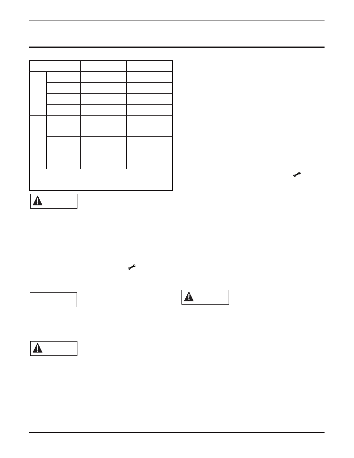
Table 2: Recommended Combustion Levels
Failure to perform a complete combustion test at both
high and low input rates may result in incomplete combus-
tion and the production of carbon monoxide, which can
cause severe personal injury, death or substantial property
damage.
2. Manually place the appliance into high fire mode by
pressing both the service button “ ” with “+” but-
ton simultaneously on the control panel display two
times.
The control panel will display a H followed by the current
appliance temperature when placed into high fire test
mode.
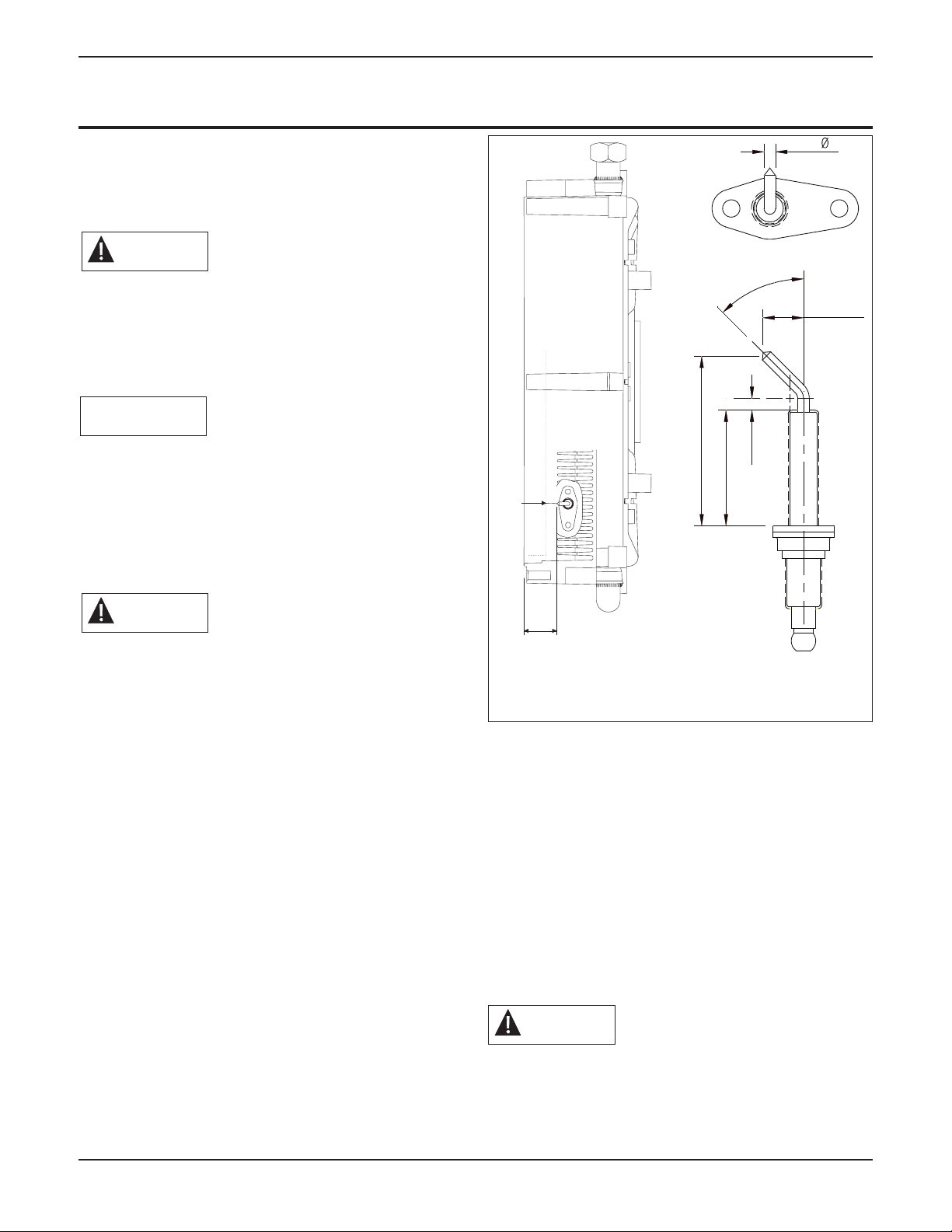
The THROTTLE SCRE on the CHALLENGER’s gas valve
works opposite than the PRESTIGE. If you turn the
CHALLENGER’s throttle screw clockwise you increase the
input, CO2and CO of the appliance. EXERCISE CARE!
3. f the combustion levels during high fire are outside
the recommended combustion settings adjust the
THROTTLE SCREW (see Figs. 3 & 4 on page 5)
using a T15 Torx wrench as follows:
Counter-clockwise adjustment of the THROTTLE
SCREW at High Fire:
O2 increases and CO2 decreases
Clockwise adjustment of the THROTTLE SCREW
at High Fire:
O2 decreases and CO2 increases
4. Once the combustion level is set and recorded at
high fire, manually place the appliance into low fire
mode by pressing the service button “ ” with “-”
button simultaneously on the control display once.
The control panel will display a L followed by the current
appliance temperature when placed into low fire test
mode.
5. f the combustion levels during low fire are not within
0.0 to 0.4% CO2 lower than the combustion level
measured at high fire, remove the offset pressure
cover screw and adjust the OFFSET SCREW using
a T15 Torx wrench as follows (see Figs. 3 & 4 on
page 5):
The OFFSET SCRE adjustment on the CHALLENGER’S gas
valve is very sensitive. A small adjustment will have a sig-
nificant effect.
Counter-clockwise adjustment of the OFFSET
SCREW at Low Fire:
O2increases and CO2 decreases
Clockwise adjustment of the OFFSET SCREW at
Low Fire:
O2decreases and CO2 increases
NOTICE
WARNING
NOTICE
WARNING
WARNING
Combustion Levels Natural Gas Propane Gas
High Fire
DOOR OFF*
CO2Range 9% to 10.1% 10.5% to 11.1%
CO2Target 9.0% 10.8%
O2Range 3.0% - 5.0% 4.1% - 5.0%
O2Target 5.0% 4.5%
Low Fire
CO2Range 0% - 0.4% < H.F
9.0% min.
0% - 0.4% < H.F
10.5% min.
O2Range 0% - 0.6% > H.F
5.0% max.
0% - 0.6% > H.F
5.0% max.
CO Max. 100 ppm 150 ppm
* Door On can raise the maximum allowable CO2by
0.4 or lower the minimum allowable 02by 0.6.
6. Confirm the combustion levels at both high fire and
low fire meet the requirements listed in Table 2 on
page 4.
7. Press the “+” and “-” button simultaneously to cancel
high or low fire mode. Test mode will time out in
approximately 10 minutes.
8. Replace offset cover screw.
9. Check the flame pattern through the inspection port
on the left side of the heat exchanger. The flame
should be blue and stable and should be the length
of the burner.
10. Replace the front jacket panel and secure with the
two Phillips head mounting screws at the control
panel.
11. Return appliance back to service.
CHALLENGER
Natural Gas to Propane Instructions
2010-25 CHALLENGER Natural to Propane nst.
Date 10/6/2016
Offset Pressure
Cover Screw
Throttle Screw
Offset Pressure Port
Inlet Gas Supply
Pressure Port
Flow direction
Fig. 3: Original Gas Valve
Fig. 4: Updated Gas Valve
88382703

Other manuals for CHALLENGER CC 85

3

This manual suits for next models

10

Other TriangleTube Gas Heater manuals

TriangleTube PSRKIT83 User manual

TriangleTube

TriangleTube PSRKIT83 User manual

TriangleTube INSRKIT08 User manual

TriangleTube

TriangleTube INSRKIT08 User manual

TriangleTube Delta Manual

TriangleTube

TriangleTube Delta Manual

TriangleTube INSRKIT58 User manual

TriangleTube

TriangleTube INSRKIT58 User manual

TriangleTube PTRKIT111 Use and care manual

TriangleTube

TriangleTube PTRKIT111 Use and care manual

Popular Gas Heater manuals by other brands

Kinder Cameo BF Installation and maintenance instructions

Kinder

Kinder Cameo BF Installation and maintenance instructions

Williams 2509822A owner's manual

Williams

Williams 2509822A owner's manual

New Buck Corporation 34 user manual

New Buck Corporation

New Buck Corporation 34 user manual

Clarke DEVIL 910SS User instructions

Clarke

Clarke DEVIL 910SS User instructions

HEATSTRIP TGH34PL Assembly and operating instructions

HEATSTRIP

HEATSTRIP TGH34PL Assembly and operating instructions

FMI MF42INR OWNER'S OPERATION AND INSTALLATION MANUAL

FMI

FMI MF42INR OWNER'S OPERATION AND INSTALLATION MANUAL

Desa Firewerks MPF24VNA OWNER'S OPERATION AND INSTALLATION MANUAL

Desa

Desa Firewerks MPF24VNA OWNER'S OPERATION AND INSTALLATION MANUAL

Totai 16/DK 1001RR Instructions for use

Totai

Totai 16/DK 1001RR Instructions for use

Temp-Heat THP-400A Installation and service manual

Temp-Heat

Temp-Heat THP-400A Installation and service manual

Aletra ATLX 55 Installation and maintenance manual

Aletra

Aletra ATLX 55 Installation and maintenance manual

Desa LSFG20NT Safety information and installation manual

Desa

Desa LSFG20NT Safety information and installation manual

Empire Heating Systems RH-50-6 owner's manual

Empire Heating Systems

Empire Heating Systems RH-50-6 owner's manual

Reznor RHC DJL 4000 Series Installation, commissioning, servicing

Reznor

Reznor RHC DJL 4000 Series Installation, commissioning, servicing

Desa CSG3930PR OWNER'S OPERATION AND INSTALLATION MANUAL

Desa

Desa CSG3930PR OWNER'S OPERATION AND INSTALLATION MANUAL

Desa VDL18PR OWNER'S OPERATION AND INSTALLATION MANUAL

Desa

Desa VDL18PR OWNER'S OPERATION AND INSTALLATION MANUAL

Dynavent DNV25NB OWNER'S OPERATION AND INSTALLATION MANUAL

Dynavent

Dynavent DNV25NB OWNER'S OPERATION AND INSTALLATION MANUAL

HOLZMANN MASCHINEN GOF4200 user manual

HOLZMANN MASCHINEN

HOLZMANN MASCHINEN GOF4200 user manual

MrHeater MH125LP Operating instructions and owner's manual

MrHeater

MrHeater MH125LP Operating instructions and owner's manual

manuals.online logo
manuals.online logoBrands
  • About & Mission
  • Contact us
  • Privacy Policy
  • Terms and Conditions

Copyright 2025 Manuals.Online. All Rights Reserved.