Tribe LUMIPIX12TRIIP User manual
LUMIPIX12TRIIP
OUTDOOR LINEAR COLORCHANGER
USER MANUAL
MANUALE UTENTE
EN - IT

All rights reserved by Music & Lights S.r.l. No part of this instruction manual may be
reproduced in any form or by any means for any commercial use.
In order to improve the quality of products, Music&Lights S.r.l. reserves the right to modify the
characteristics stated in this instruction manual at any time and without prior notice.
All revisions and updates are available in the ‘manuals’ section on site www.musiclights.it
REV. 04-02/19

1
LUMIPIX12TRI IP
Packing content • LUMIPIX12TRI IP
• Power extension cable
• Signal extension cable
• Mount bracket (2 pc.)
• User manual
TABLE OF CONTENTS Safety
General instructions
Warnings and installation precautions
1 Introduction
1. 1 Description
1. 2 Technical specications
1. 3 Operating elements and connections
2 Installation
2. 1 Mounting
3 Functions and settings
3. 1 Operation
3. 2 Basic
3. 3 Menu structure
3. 4 Auto Show
3. 5 Static color
3. 6 Manual color
3. 7 Master/Slave mode
3. 8 Linking
3. 9 DMX mode
3. 10 DMX addressing
3. 11 Activate the password
3. 12 Connection of the DMX line
3. 13 Construction of the DMX termination
3. 14 DMX control
4 Maintenance
4. 1 Maintenance and cleaning the unit
4. 2 Trouble shooting
2
2
3
3
4
5
6
6
7
8
8
8
8
9
9
9
9
10
10
11
14
14

LUMIPIX12TRI IP
2
SAFETY
General instruction
• The products referred to in this manual conform to the European Community Directives and are there-
fore marked with .
• The unit is supplied with hazardous network voltage (230V~). Leave servicing to skilled personnel only.
Never make any modications on the unit not described in this instruction manual, otherwise you will
risk an electric shock.
• Connection must be made to a power supply system tted with ecient earthing (Class I appliance ac-
cording to standard EN 60598-1). It is, moreover, recommended to protect the supply lines of the units
from indirect contact and/or shorting to earth by using appropriately sized residual current devices.
• The connection to the main network of electric distribution must be carried out by a qualied electrical
installer. Check that the main frequency and voltage correspond to those for which the unit is designed
as given on the electrical data label.
• This unit is not for home use, only professional applications.
• Never use the xture under the following conditions:
- in places subject to vibrations or bumps;
- in places with a temperature of over 45 °C.
• Make certain that no inammable liquids, water or metal objects enter the xture.
• Do not dismantle or modify the xture.
• All work must always be carried out by qualied technical personnel. Contact the nearest sales point for
an inspection or contact the manufacturer directly.
• If the unit is to be put out of operation denitively, take it to a local recycling
plant for a disposal which is not harmful to the environment.
Warnings and installation precautions
• If this device will be operated in any way dierent to the one described in this manual, it may suer
damage and the guarantee becomes void. Furthermore, any other operation may lead to dangers like
short circuit, burns, electric shock, etc.
• Before starting any maintenance work or cleaning the projector, cut o power from the main supply.
• Always additionally secure the projector with the safety rope.When carrying out any work, always com-
ply scrupulously with all the regulations (particularly regarding safety) currently in force in the country
in which the xture’s being used.
• Install the xture in a well ventilated place.
• Keep any inammable material at a safe distance from the xture.
• Shields, lenses or ultraviolet screens shall be changed if they have become damaged to such an extent
that their eectiveness is impaired.
• The lamp (LED) shall be changed if it has become damaged or thermally deformed.
• Never look directly at the light beam. Please note that fast changes in lighting, e. g. ashing light, may
trigger epileptic seizures in photosensitive persons or persons with epilepsy.
• Do not touch the product’s housing when operating because it may be very hot.
WARNING! Before carrying out any operations with the unit, carefully read this instruction
manual and keep it with cure for future reference. It contains important information about
the installation, usage and maintenance of the unit.

3
LUMIPIX12TRI IP
- 1 - INTRODUCTION
1.1 DESCRIPTION
LUMIPIX12TRIIP is an outdoor linear colorchanger equipped with 12 high-eciency RGB/FullColor LEDs
(3W each) in a 1mt format. Control system is customizable allowing“Pixel Control”, independent selection
of each LED, from 3 to 36 channels. LUMIPIX12TRIIP oers advanced possibilities in eect generation as
LED video or sound activated arrays.
1.2 TECHNICAL SPECIFICATIONS
Light source and optics
• 2 x 3W RGB/FC high-eciency LEDS
• Beam angle: 16°
• Field angle: 30°
• Colour synthesis: RGB/Fullcolour mixing (>16 million colours) for a limitless colour range
• LEDs average life span: >50’000h
Electronics and features
• LED display control panel
• Several DMX selectable congurations (3, 4, 6, 7, 9, 12, 18, 36 channels) for advanced or basic control
- 3 channels: RGB
- 4 channels: RGB, dimmer
- 6 channels: RGB x 2
- 7 channels: RGB, macro, auto, dimmer
- 9 channels: RGB x 3
- 12 channels: RGB x 4
- 18 channels: RGB x 6
- 36 channels: RGB x 12
• Auto mode: built-in programs with execution speed adjustment
• Static colour mode: selection of static colour
• Master/Slave mode: for synchronized operation of more units linked in a chain
• Linear and“stepless” transition between DMX values
• Flicker free operations (400Hz)
Structure and Power supply
• Sturdy die-cast aluminum body conceived for long-time durability and demanding applications
• Tempered glass front panel
• Internal Protection: IP67
• Pressure and temperature balance through GORE membrane vents
• Power (shuko) and data (xlr-3p) adapter cables included
• Double hanging bracket suitable for safe hanging and oor positioning
• Power unit: 100-240V 50/60Hz
• IN / OUT wiring signal and power connections through IPCONs
• Average power consumption: 40W (output up to 16 projectors)
• Weight: 6,5 kg
• Dimensions (WxHxD): 993x100x173mm
LUMIPIX12TRI IP
4
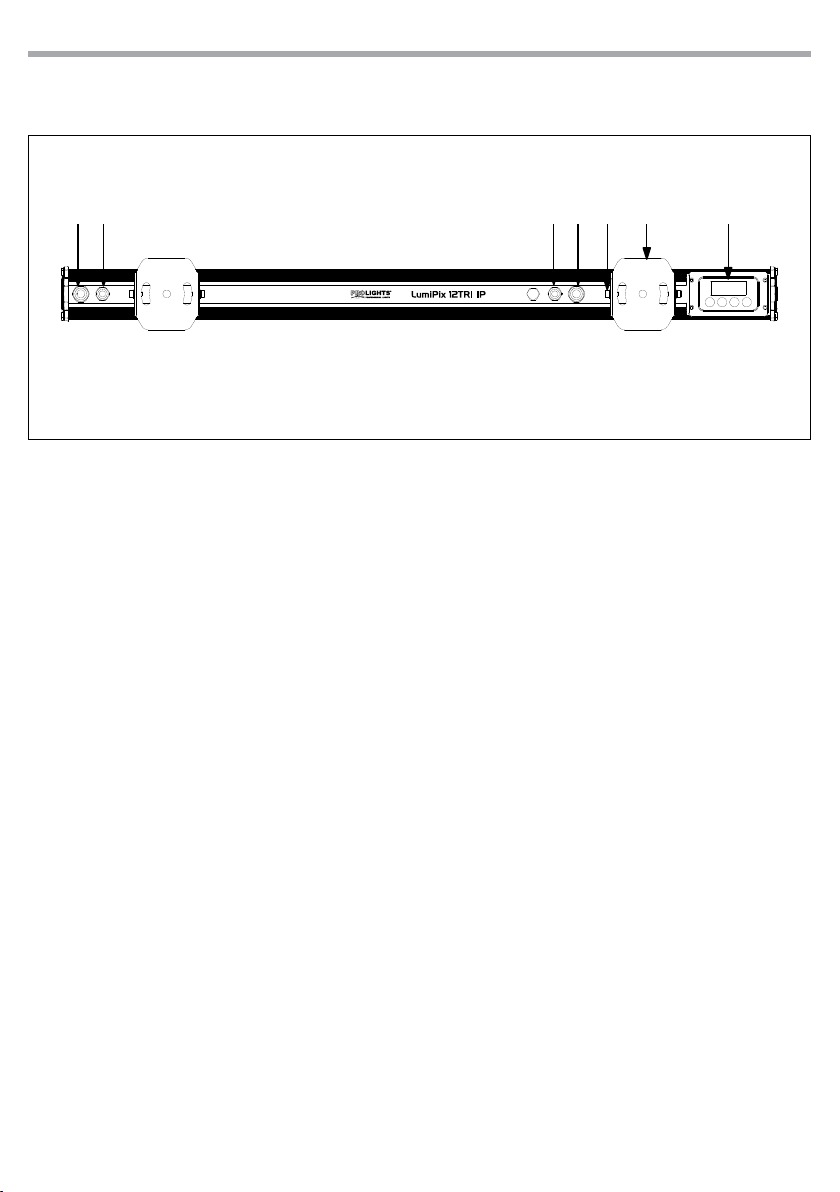
1.3 OPERATING ELEMENTS AND CONNECTIONS
Fig.1
1. CONTROL PANEL with display and 4 button
used to access the control panel functions
and manage them.
2. MOUNTING BRACKET
3. SCREW for the mounting bracket
4. POWER IN: for connection to a socket
(100-240V~/50-60Hz) via the supplied mains
cable.
5. DMX IN (3-pole XLR):
1 = ground, 2 = DMX -, 3 = DMX +
6. DMX OUT (3-pole XLR):
1= ground, 2 = DMX -, 3 = DMX +
7. POWER OUT: connect to supply power to the
next unit
MENU UP DOWN ENTER
124 3567
Rear panel
5
LUMIPIX12TRI IP
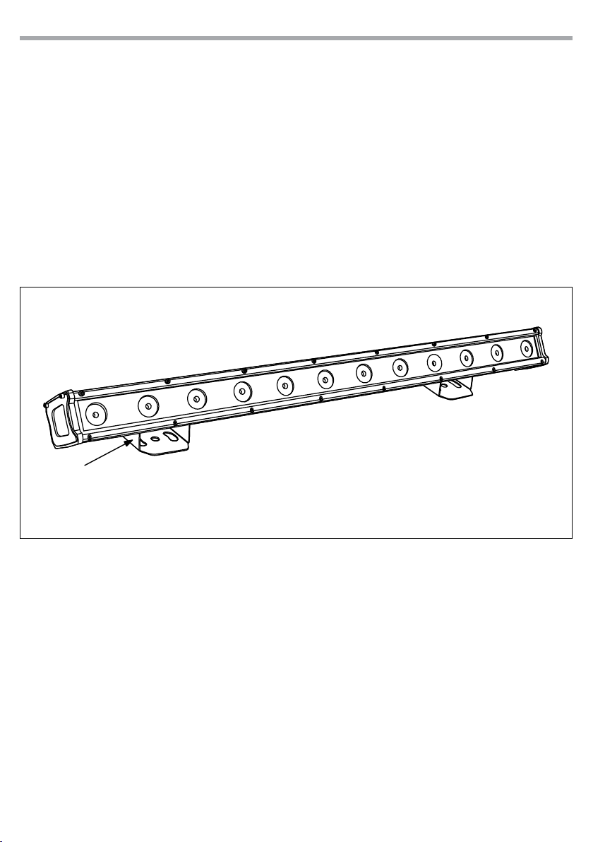
- 2 - INSTALLATION
2.1 MOUNTING
LUMIPIX12TRI IP may be set up on a solid and even surface. The unit can also be mounted upside down to
a cross arm. For xing, stable mounting clips are required. The mounting place must be of sucient stabil-
ity and be able to support a weight of 10 times of the unit’s weight.
When carrying out any installation, always comply scrupulously with all the regulations (particularly re-
garding safety) currently in force in the country in which the xture’s being used.
• Install the projector at a suitable location by means of the mounting bracket (2).
• Always additionally secure the projector with the safety rope from falling down. For this purpose, fas-
ten the safety rope at a suitable position so that the maximum fall of the projector will be 20 cm.
• Adjust the projector and use the screw to slightly release or tighten the locking mechanism of the
bracket if is necessary.
Fig.2
2
LUMIPIX12TRI IP
6
- 3 - FUNCTIONS AND SETTINGS
3.1 OPERATION
Connect the supplied main cable to a socket (100-240V~/50-60Hz). Then the unit is ready for operation
and can be operated via a DMX controller or it independently performs its show program in succession.
To switch o, disconnect the mains plug from the socket. For a more convenient operation it is recom-
mended to connect the unit to a socket which can be switched on and o via a light switch.
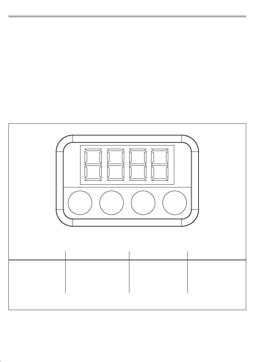
3.2 BASIC
Access control panel functions using the four panel buttons located directly underneath the LED Display
(g.3).
Fig.3 - Functions of the buttons
MENU UP DOWN ENTER
MENU UP DOWN ENTER
Used to access the menu or
to return a previous menu
option
Navigates downwards through
the menu list and increases
the numeric value when in a
function
Navigates upwards through
the menu list and decreases
the numeric value when in
a function
Used to select and store the
current menu or conrm the
current function value or
option within a menu

7
LUMIPIX12TRI IP
3.3 MENU STRUCTURE
MENU (LEVEL 1) (LEVEL 2) (LEVEL 3) REMARK
1 3 CH d (1-512)
2 4 CH d (1-512)
3 6 CH d (1-512)
4 7 CH d (1-512)
5 9 CH d (1-512)
6 12 CH d (1-512)
7 18 CH d (1-512)
8 36 CH d (1-512)
9 C-- C 1
C 2
C 3
C 4
C 5
C 6
C 7
10 P-- P 1
P 2
P 3
P 4
P 5
P 6
11 S-- S (1-100)
12 Slr A(1-126) Master/Slave mode
13 U-- r(0-255)
g(0-255)
b(0-255)
14 PASS On To unlocking, please press
OFF UP-DOWN-UP-DOWN-ENTER

LUMIPIX12TRI IP
8
3.4 AUTO SHOW
This xture has a built-in automatic program. To access this, please see the below instructions:
• Press the button MENU so many times until shows [P--], then press the button ENTER.
• Using UP/DOWN button, select one of the programs [P1 - P6].
• Press the button ENTER to conrm.
• Press the button MENU until [S--] appears on the display.
• Use the button UP/DOWN to select the auto programs speed [S001 - S100] (slow-fast).
• Press the button ENTER save the setting.
3.5 STATIC COLOR
This xture has the ability to accept custom static color settings. Access these chases via the control panel
on the back of the xture.
• Press the button MENU so many times until shows [C--], then press the button ENTER.
• Using UP/DOWN button, select one of the programs [C1 - C7].
• Press the button ENTER to conrm.
• Press the MENU button to go back or to meet the waiting time to exit the setup menu.
3.6 MANUAL COLOR
This mode allows to combine the colors red, green and blue (r, g, b).
• Press the button MENU so many times until the display shows [U--], then press the button ENTER.
• Select the color [r, g, b] through the buttons UP/DOWN.
• Press the button ENTER to conrm.
• Using UP/DOWN button, select the desired color value [000 - 255].
• Press ENTER button to continue to the next color.
• Continue until the desired mix is obtained.
• Press the MENU button to go back or to meet the waiting time to exit the setup menu.
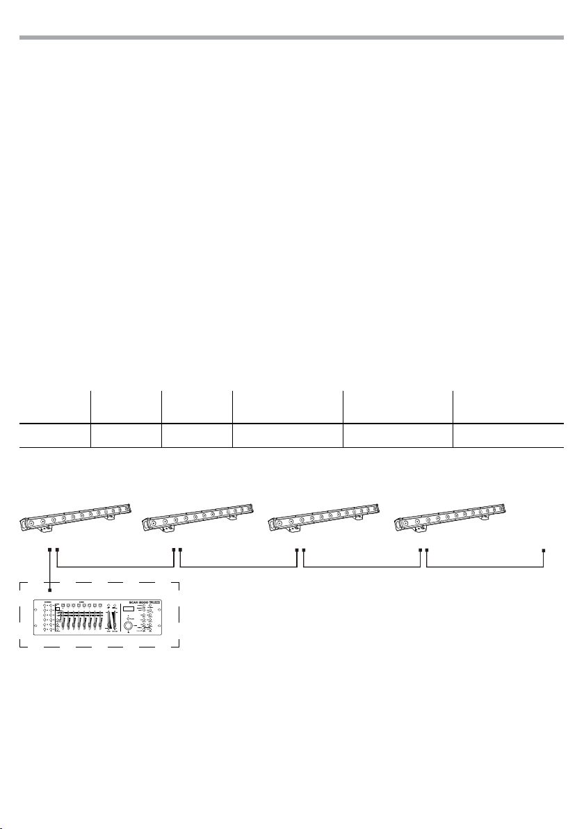
3.7 MASTER/SLAVE MODE
This mode will allow you to link up the units together without a controller. Choose a unit to function as the
Master. The unit must be the rst unit in line; other units will work as slave.
• Set on master xture the desired program (see section 3.4).
• Press the button MENU so many times until the display shows [Slr] and press the button ENTER.
NOTE
• Sync feature: [Slr] is [A1]
• Asynchronous serial feature
- Master settings the number of [Slr] is for the online units;
- Slave set the online location by [Slr]
Example for 10 units
• Use standard DMX cables to daisy chain your units together via the DMX connector on the rear of the
units. For longer cable runs we suggest a terminator at the last xture (see page 11).
1 2 3 ... 10
master slave slave ... slave
A10 A2 A3 ... A10
9
LUMIPIX12TRI IP
Number of
DMX channels
Start address
(example)
DMX Address
occupied
Next possible start
address for unit No. 1
Next possible start
address for unit No. 2
Next possible start
address for unit No. 3
4 33 33-36 37 41 45
3.8 LINKING
1. Connect the DMX OUT of the master unit via 3-pole XLR cable to the DMX IN of the rst slave unit.
2. Connect the DMX OUT of the rst slave unit to the DMX IN of the second slave unit, etc. until all units
are connected in a chain.
3.9 DMX MODE
• Press the button MENU so many times until shows [CH3], [CH4], [CH6], [CH7], [CH9], [CH12], [CH18] or [CH10] and
press the button ENTER to conrm.
• Press the button UP/DOWN to select the desired DMX address [d001 - d512]. Press and hold to scroll
quickly. Press ENTER button to store.
The tables on page 12 indicate the operating mode and DMX value. The LUMIPIX12TRI IP is equipped with
3-pole XLR connections.
3.10 DMX ADDRESSING
To able to operate the LUMIPIX12TRI IP with a light controller, adjust the DMX start address for the rst a
DMX channel. If e. g. address 33 on the controller is provided for controlling the function of the rst DMX
channel, adjust the start address 33 on the LUMIPIX12TRI IP. The other functions of the light eect panel
are then automatically assigned to the following addresses.
An example with the start address 33 is shown below:
. . . . . . . . . . . .
DMX512 Controller
Example 4 DMX channels configuration
Fig.4
DMX Address: 33 DMX Address: 45DMX Address: 37 DMX Address: 41
3.11 ACTIVATE THE PASSWORD
Enter the KEY mode to select whether the access password is on or o.
• Press the button MENU so many times until show [PASS] and press the button ENTER to conrm.
• Select [ON] or [OFF].
When the xture is set as pass [ON], after 30 seconds or turn on the xture next time, the xture will need
an access password to enter the display menu control.
NOTE - The factory access password is UP + DOWN + UP + DOWN. Press ENTER to conrm the access.
LUMIPIX12TRI IP
10
Fig.5
Fig.6
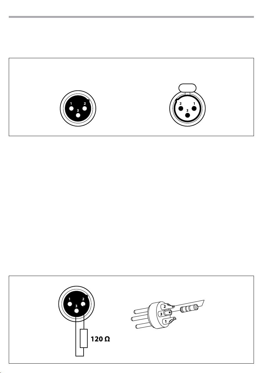
3.12 CONNECTION OF THE DMX LINE
DMX connection employs standard XLR connectors. Use shielded pair-twisted cables with 120Ω imped-
ance and low capacity.
The following diagram shows the connection mode:
ATTENTION
The screened parts of the cable (sleeve) must never be connected to the system’s earth, as this would
cause faulty xture and controller operation.
Over long runs can be necessary to insert a DMX level matching amplier.
For those connections the use of balanced microphone cable is not recommended because it cannot
transmit control DMX data reliably.
• Connect the controller DMX input to the DMX output of the rst unit.
• Connect the DMX output to the DMX input of the following unit. Connect again the output to the input
of the following unit until all the units are connected in chain.
• When the signal cable has to run longer distance is recommended to insert a DMX termination on the
last unit.
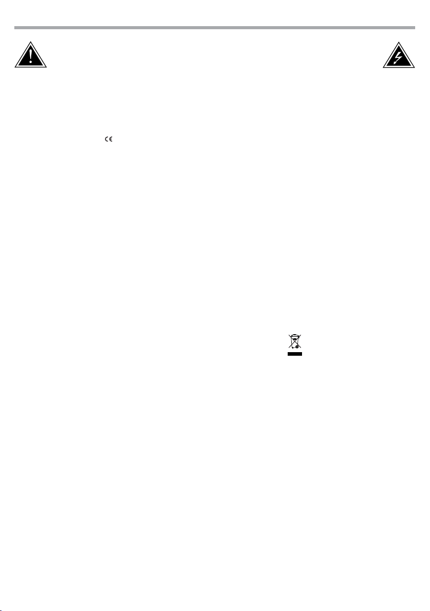
3.13 CONSTRUCTION OF THE DMX TERMINATION
The termination avoids the risk of DMX 512 signals being reected back along the cable when they reach-
es the end of the line: under certain conditions and with certain cable lengths, this could cause them to
cancel the original signals.
The termination is prepared by soldering a 120Ω 1/4 W resistor between pins 2 and 3 of the 5-pin male XLR
connector, as shown in gure.
DMX - OUTPUT
XLR socket
DMX - INPUT
XLR plug
Pin1 : GND - Shield
Pin2 : - Negative
Pin3 : + Positive
Example:
3 pin XLR connector

11
LUMIPIX12TRI IP
3.14 DMX CONTROL
MODE FUNCTION DMX
Value
3 Ch
1RED
0~100% 000 - 255
2GREEN
0~100% 000 - 255
3BLUE
0~100% 000 - 255
MODE FUNCTION DMX
Value
9 Ch
1RED (LED1-4)
0~100% 000 - 255
2GREEN (LED1-4)
0~100% 000 - 255
3BLUE (LED1-4)
0~100% 000 - 255
4RED (LED5-8)
0~100% 000 - 255
5GREEN (LED5-8)
0~100% 000 - 255
6BLUE (LED5-8)
0~100% 000 - 255
7RED (LED9-12)
0~100% 000 - 255
8GREEN (LED9-12)
0~100% 000 - 255
9BLUE (LED9-12)
0~100% 000 - 255
MODE FUNCTION DMX
Value
7 Ch
1RED
0~100% 000 - 255
2GREEN
0~100% 000 - 255
3BLUE
0~100% 000 - 255
4
COLOR
No function
Strobe slow to fast
000 - 015
016 - 255
5AUTO SPEED
Only when CH8 has Auto 1-5 activated 000 - 255
6
PROGRAMS
No function
Pulse eect 0~100%
Pulse eect 100%~0
Pulse eect 0~100%~0
Chase program
Auto fade transition
Auto snap transition
Auto snap transition
Auto programs
000 - 031
032 - 063
064 - 095
096 - 114
115 - 127
128 - 159
160 - 191
192 - 223
224 - 255
7DIMMER
0~100% 000 - 255
MODE FUNCTION DMX
Value
4 Ch
1RED
0~100% 000 - 255
2GREEN
0~100% 000 - 255
3BLUE
0~100% 000 - 255
4DIMMER
0~100% 000 - 255
MODE FUNCTION DMX
Value
6 Ch
1RED (LED1-6)
0~100% 000 - 255
2GREEN (LED1-6)
0~100% 000 - 255
3BLUE (LED1-6)
0~100% 000 - 255
4RED (LED7-12)
0~100% 000 - 255
5GREEN (LED7-12)
0~100% 000 - 255
6BLUE (LED7-12)
0~100% 000 - 255

LUMIPIX12TRI IP
12
MODE FUNCTION DMX
Value
12 Ch
1RED (LED1-3)
0~100% 000 - 255
2GREEN (LED1-3)
0~100% 000 - 255
3BLUE (LED1-3)
0~100% 000 - 255
4RED (LED4-6)
0~100% 000 - 255
5GREEN (LED4-6)
0~100% 000 - 255
6BLUE (LED4-6)
0~100% 000 - 255
7RED (LED7-9)
0~100% 000 - 255
8GREEN (LED7-9)
0~100% 000 - 255
9BLUE (LED7-9)
0~100% 000 - 255
10 RED (LED10-12)
0~100% 000 - 255
11 GREEN (LED10-12)
0~100% 000 - 255
12 BLUE (LED10-12)
0~100% 000 - 255
MODE FUNCTION DMX
Value
18 Ch
1RED (LED1-2)
0~100% 000 - 255
2GREEN (LED1-2)
0~100% 000 - 255
3BLUE (LED1-2)
0~100% 000 - 255
4RED (LED3-4)
0~100% 000 - 255
5GREEN (LED3-4)
0~100% 000 - 255
6BLUE (LED3-4)
0~100% 000 - 255
7RED (LED5-6)
0~100% 000 - 255
8GREEN (LED5-6)
0~100% 000 - 255
9BLUE (LED5-6)
0~100% 000 - 255
10 RED (LED7-8)
0~100% 000 - 255
11 GREEN (LED7-8)
0~100% 000 - 255
12 BLUE (LED7-8)
0~100% 000 - 255
13 RED (LED9-10)
0~100% 000 - 255
14 GREEN (LED9-10)
0~100% 000 - 255
15 BLUE (LED9-10)
0~100% 000 - 255
16 RED (LED11-12)
0~100% 000 - 255
17 GREEN (LED11-12)
0~100% 000 - 255
18 BLUE (LED11-12)
0~100% 000 - 255

13
LUMIPIX12TRI IP
MODE FUNCTION DMX
Value
36 Ch
1RED (LED1)
0~100% 000 - 255
2GREEN (LED1)
0~100% 000 - 255
3BLUE (LED1)
0~100% 000 - 255
4RED (LED2)
0~100% 000 - 255
5GREEN (LED2)
0~100% 000 - 255
6BLUE (LED2)
0~100% 000 - 255
7RED (LED3)
0~100% 000 - 255
8GREEN (LED3)
0~100% 000 - 255
9BLUE (LED3)
0~100% 000 - 255
10 RED (LED4)
0~100% 000 - 255
11 GREEN (LED4)
0~100% 000 - 255
12 BLUE (LED4)
0~100% 000 - 255
13 RED (LED5)
0~100% 000 - 255
14 GREEN (LED5)
0~100% 000 - 255
15 BLUE (LED5)
0~100% 000 - 255
16 RED (LED6)
0~100% 000 - 255
17 GREEN (LED6)
0~100% 000 - 255
18 BLUE (LED6)
0~100% 000 - 255
MODE FUNCTION DMX
Value
36 Ch
19 RED (LED7)
0~100% 000 - 255
20 GREEN (LED7)
0~100% 000 - 255
21 BLUE (LED7)
0~100% 000 - 255
22 RED (LED8)
0~100% 000 - 255
23 GREEN (LED8)
0~100% 000 - 255
24 BLUE (LED8)
0~100% 000 - 255
25 RED (LED9)
0~100% 000 - 255
26 GREEN (LED9)
0~100% 000 - 255
27 BLUE (LED9)
0~100% 000 - 255
28 RED (LED10)
0~100% 000 - 255
29 GREEN (LED10)
0~100% 000 - 255
30 BLUE (LED10)
0~100% 000 - 255
31 RED (LED11)
0~100% 000 - 255
32 GREEN (LED11)
0~100% 000 - 255
33 BLUE (LED11)
0~100% 000 - 255
34 RED (LED12)
0~100% 000 - 255
35 GREEN (LED12)
0~100% 000 - 255
36 BLUE (LED12)
0~100% 000 - 255

LUMIPIX12TRI IP
14
- 4 - MAINTENANCE
4.1 MAINTENANCE AND CLEANING THE UNIT
• Make sure the area below the installation place is free from unwanted persons during setup.
• Switch o the unit, unplug the main cable and wait until the unit has cooled down.
• All screws used for installing the device and any of its parts should be tightly fastened and should not
be corroded.
• Housings, xations and installation spots (ceiling, trusses, suspensions) should be totally free from any
deformation.
• The main cables must be in impeccable condition and should be replaced immediately even when a
small problem is detected.
• It is recommended to clean the front at regular intervals, from impurities caused by dust, smoke, or
other particles to ensure that the light is radiated at maximum brightness. For cleaning, disconnect the
main plug from the socket. Use a soft, clean cloth moistened with a mild detergent. Then carefully wipe
the part dry. For cleaning other housing parts use only a soft, clean cloth. Never use a liquid, it might
penetrate the unit and cause damage to it.
4.2 TROUBLESHOOTING
Problems Possible causes Checks and remedies
Fixture does not light up
• No mains supply
• Dimmer fader set to 0
• All color faders set to 0
• Faulty LED
• Faulty LED board
• Check the power supply voltage
• Increase the value of the dimmer channels
• Increase the value of the color channels
• Replace the LED board
• Replace the LED board
General low light intensity • Dirty lens assembly
• Misaligned lens assembly
• Clean the xture regularly
• Install lens assembly properly
Fixture does not power up
• No power
• Loose or damaged power cord
• Faulty internal power supply
• Check for power on power outlet
• Check power cord
• Replace internal power supply
Fixture does not respond to DMX
• Wrong DMX addressing
• Damaged DMX cables
• Bouncing signals
• Check control panel and unit addressing
• Check DMX cables
• Install terminator as suggested
Contact an authorized service center in case of technical problems or not reported in the table can not be
resolved by the procedure given in the table.


Music & Lights S.r.l. si riserva ogni diritto di elaborazione in qualsiasi forma delle presenti istruzioni per l’uso.
La riproduzione - anche parziale - per propri scopi commerciali è vietata.
Al ne di migliorare la qualità dei prodotti, la Music&Lights S.r.l. si riserva la facoltà di modicare, in
qualunque momento e senza preavviso, le speciche menzionate nel presente manuale di istruzioni.
Tutte le revisioni e gli aggiornamenti sono disponibili nella sezione 'Manuali' sul sito www.musiclights.it

3
LUMIPIX12TRI IP
• LUMIPIX12TRI IP
• Estensione cavo di alimentazione
• Estensione cavo di segnale
• Staa di ssaggio (2pz.)
• Manuale utente
Contenuto dell'imballo:
INDICE Sicurezza
Avvertenze generali
Attenzioni e precauzioni per l’installazione
1 Introduzione
1. 1 Descrizione
1. 2 Speciche tecniche
1. 3 Elementi di comando e di collegamento
2 Installazione
2. 1 Montaggio
3 Funzioni e impostazioni
3. 1 Funzionamento
3. 2 Impostazione base
3. 3 Struttura menu
3. 4 Auto Show
3. 5 Static color
3. 6 Manual color
3. 7 Modalità Master/Slave
3. 8 Collegamento
3. 9 Modalità DMX
3. 10 Indirizzamento DMX
3. 11 Attivazione password
3. 12 Collegamenti della linea DMX
3. 13 Costruzione del terminatore DMX
3. 14 Canali DMX
4 Manutenzione
4. 1 Manutenzione e pulizia del sistema ottico
4. 2 Risoluzione dei problemi
4
4
5
5
6
7
8
8
9
10
10
10
10
11
11
11
11
12
12
13
16
16
LUMIPIX12TRI IP
4
ATTENZIONE! Prima di effettuare qualsiasi operazione con l’unità, leggere con attenzione
questo manuale e conservarlo accuratamente per riferimenti futuri. Contiene informazioni
importanti riguardo l’installazione, l’uso e la manutenzione dell’unità.
SICUREZZA
Avvertenze generali
• I prodotti a cui questo manuale si riferisce sono conformi alle Direttive della Comunità Europea e per-
tanto recano la sigla .
• Il dispositivo funziona con pericolosa tensione di rete 230V~. Non intervenire mai al suo interno al di
fuori delle operazioni descritte nel presente manuale; esiste il pericolo di una scarica elettrica.
• È obbligatorio eettuare il collegamento ad un impianto di alimentazione dotato di un’eciente messa
a terra (apparecchio di Classe I secondo norma EN 60598-1). Si raccomanda, inoltre, di proteggere le
linee di alimentazione delle unità dai contatti indiretti e/o cortocircuiti verso massa tramite l’uso di
interruttori dierenziali opportunamente dimensionati.
• Le operazioni di collegamento alla rete di distribuzione dell’energia elettrica devono essere eettuate
da un installatore elettrico qualicato. Vericare che frequenza e tensione della rete corrispondono alla
frequenza ed alla tensione per cui l’unità è predisposta, indicate sulla targhetta dei dati elettrici.
• L’unità non per uso domestico, solo per uso professionale.
• Evitare di utilizzare l’unità:
- in luoghi soggetti a vibrazioni, o a possibili urti;
- in luoghi a temperatura superiore ai 45°C.
• Evitare che nell’unità penetrino liquidi inammabili, acqua o oggetti metallici.
• Non smontare e non apportare modiche all’unità.
• Tutti gli interventi devono essere sempre e solo eettuati da personale tecnico qualicato. Rivolgersi al
più vicino centro di assistenza tecnica autorizzato.
• Se si desidera eliminare il dispositivo denitivamente, consegnarlo
per lo smaltimento ad un’istituzione locale per il riciclaggio.
Attenzioni e precauzioni per l’installazione
• Se il dispositivo dovesse trovarsi ad operare in condizioni dierenti da quelle descritte nel presente
manuale, potrebbero vericarsi dei danni; in tal caso la garanzia verrebbe a decadere. Inoltre, ogni altra
operazione potrebbe provocare cortocircuiti, incendi, scosse elettriche, rotture etc.
• Prima di iniziare qualsiasi operazione di manutenzione o pulizia sull’unità togliere la tensione dalla rete
di alimentazione.
• È assolutamente necessario proteggere l’unità per mezzo di una fune di sicurezza. Nell’eseguire qual-
siasi intervento attenersi scrupolosamente a tutte le normative (in materia di sicurezza) vigenti nel
paese di utilizzo.
• Installare l’unità in un luogo ben ventilato.
• Mantenere i materiali inammabili ad una distanza di sicurezza dall’unità.
• I ltri, le lenti o gli schermi ultravioletti se danneggiati possono limitare la loro ecienza.
• I LED devono essere sostituiti se danneggiati o termicamente deformati.
• Non guardare direttamente il fascio luminoso. Tenete presente che i veloci cambi di luce possono pro-
vocare attacchi d’epilessia presso persone fotosensibili o epilettiche.
• Non toccare l’alloggiamento del prodotto quando è in funzione perché potrebbe essere molto caldo.
Table of contents
Languages:
Other Tribe Lighting Equipment manuals


Popular Lighting Equipment manuals by other brands


SIGNIFY
SIGNIFY LIGHTOLIER IS-MD1R Instructions for installation and operation

EuroLite
EuroLite LED STP-10 10x3W DMX user manual

SKYDANCE
SKYDANCE CXR-21A installation instructions

SHAFT
SHAFT SHE191 manual

Inspire
Inspire Olga Assembly, Use, Maintenance Manual

Lena Lighting
Lena Lighting UV-C STERILON CLEAN Installation instruction