Tribe PIXPAN9E User manual

USER MANUAL
MANUALE UTENTE
PIXPAN9E
LED MATRIX COMPOSED OF 9X15W
RGB/FC COB LED
EN - IT

All rights reserved by Music & Lights S.r.l. No part of this instruction manual may be
reproduced in any form or by any means for any commercial use.
In order to improve the quality of products, Music&Lights S.r.l. reserves the right to modify the
characteristics stated in this instruction manual at any time and without prior notice.
All revisions and updates are available in the ‘manuals’ section on site www.musiclights.it

1
PIXPAN 9E
Packing content • PIXPAN9E
• Power cord
• Mount bracket
• User manual
TABLE OF CONTENTS Safety
General instructions
Warnings and installation precautions
1 Introduction
1. 1 Description
1. 2 Technical specications
1. 3 Operating elements and connections
2 Installation
2. 1 Mounting
3 Functions and settings
3. 1 Operation
3. 2 Basic
3. 3 Menu structure
3. 4 Operation in automatic mode
3. 5 Sound active
3. 6 Master/Slave mode
3. 7 Linking
3. 8 DMX conguration
3. 9 DMX addressing
3. 10 Connection of the DMX line
3. 11 Construction of the DMX termination
3. 12 DMX control
3. 13 Static conguration
3. 14 Special function
4 Maintenance
4. 1 Maintenance and cleaning the unit
4. 2 Fuse replacement
4. 3 Trouble shooting
2
2
3
3
4
5
6
6
7
8
8
8
8
8
9
10
10
11
14
14
15
15
16
PIXPAN 9E
2
WARNING! Before carrying out any operations with the unit, carefully read this instruction
manual and keep it with cure for future reference. It contains important information about
the installation, usage and maintenance of the unit.
SAFETY
General instruction
• The products referred to in this manual conform to the European Community Directives and are there-
fore marked with .
• The unit is supplied with hazardous network voltage (230V~). Leave servicing to skilled personnel only.
Never make any modications on the unit not described in this instruction manual, otherwise you will
risk an electric shock.
• Connection must be made to a power supply system tted with ecient earthing (Class I appliance ac-
cording to standard EN 60598-1). It is, moreover, recommended to protect the supply lines of the units
from indirect contact and/or shorting to earth by using appropriately sized residual current devices.
• The connection to the main network of electric distribution must be carried out by a qualied electrical
installer. Check that the main frequency and voltage correspond to those for which the unit is designed
as given on the electrical data label.
• This unit is not for home use, only professional applications.
• Never use the xture under the following conditions:
- in places subject to vibrations or bumps;
- in places with a temperature of over 45°C. or below -5°C.
• Make certain that no inammable liquids, water or metal objects enter the xture.
• Do not dismantle or modify the xture.
• All work must always be carried out by qualied technical personnel. Contact the nearest sales point for
an inspection or contact the manufacturer directly.
• If the unit is to be put out of operation denitively, take it to a local recycling
plant for a disposal which is not harmful to the environment.
Warnings and installation precautions
• The unit for indoor use only. To prevent or reduce the risk of electrical shock or re, do not expose the
unit to rain or moisture.
• If this device will be operated in any way dierent to the one described in this manual, it may suer
damage and the guarantee becomes void. Furthermore, any other operation may lead to dangers like
short circuit, burns, electric shock, etc.
• Before starting any maintenance work or cleaning the projector, cut o power from the main supply.
• Always additionally secure the projector with the safety rope.When carrying out any work, always com-
ply scrupulously with all the regulations (particularly regarding safety) currently in force in the country
in which the xture’s being used.
• Install the xture in a well ventilated place.
• Keep any inammable material at a safe distance from the xture.
• Shields, lenses or ultraviolet screens shall be changed if they have become damaged to such an extent
that their eectiveness is impaired.
• The lamp (LED) shall be changed if it has become damaged or thermally deformed.
• Never look directly at the light beam. Please note that fast changes in lighting, e. g. ashing light, may
trigger epileptic seizures in photosensitive persons or persons with epilepsy.
• The minimum distance between the xture and surrounding walls must be more than 50 cm and the
air vents at the housing must not be covered in any case.
• The projector need to be positioned so that the objects hit by the beam of light are at least 0.1m from
the lens of the projector.
• Always store in a dry environment away from sunlight.
• When cleaning unit, please do not use solvents, since they may damage the of the unit outer nish.

3
PIXPAN 9E
- 1 - INTRODUCTION
1.1 DESCRIPTION
PIXPAN9E is a LED matrix composed of 9x15W RGB/FC COB LED, designed to revolutionize the concept of
pixel-control applied to lighting bodies with LED source.
The special optic parables in combination with LED 15W COB (chip-on-board) give to PIXPAN9E a light
unprecedented output able to impress and dazzle the audience.
Each LED of PIXPAN9E can be controlled independently, giving to the designers an advanced stage-gen-
eration eye candy eects, animations pixel-mapping, video playback and blinder.
Mechanical components on board consist of side clamp for quick assembling and coupling inserts, allow-
ing a very versatile suspension of Truss, stand or wall-creating a low resolution LED.
1.2 TECHNICAL SPECIFICATIONS
Light source and optics
• 9 x 15W RGB / FC COB LED high brightness
• Pixel pitch: 115mm
• Projection angle: 60°
• Colour synthesis: RGB color mixing / FullColor (> 16 million colors)
• LEDs average life span:> 50,000 hours
Electronics and features
• Control Panel with LED display 4char
• Several DMX congurations (3, 5, 9, 27, 31 channels) for professional or simplied control
- 3 channels: RGB
- 5 channels: Dimmer, RGB, strobe
- 9-channel: Dimmer, RGB, strobe, macro, auto, speed, dim curves
- 27-channel: RGB (9pix)
- 31-channel: RGB (9pix), car, speed, dimmer, strobe
• Sound Mode: Switch music via the internal microphone, sensitivity control
• Auto mode: preset automatic programs with speed control
• Color mode static: static reproduction of a color
• Master / Slave: For the control of several units linked in a chain
• Linear passage“stepless” DMX values
• Frequency diode anti-icker (400Hz) for video recordings
Structure and Power supply
• Cast aluminum body, degree of protection: IP33
• Forced air cooling
• Bracket for truss and rigging hardware linking multiple units
• Power supply :100-240V 50/60Hz
• Wiring IN / OUT signal and power connections through XLR3p/VDE
• Average power consumption: 139W (output up to 8 projectors)
• Weight: 6kg
• Dimensions (WxHxD): 344x344x89mm
PIXPAN 9E
4
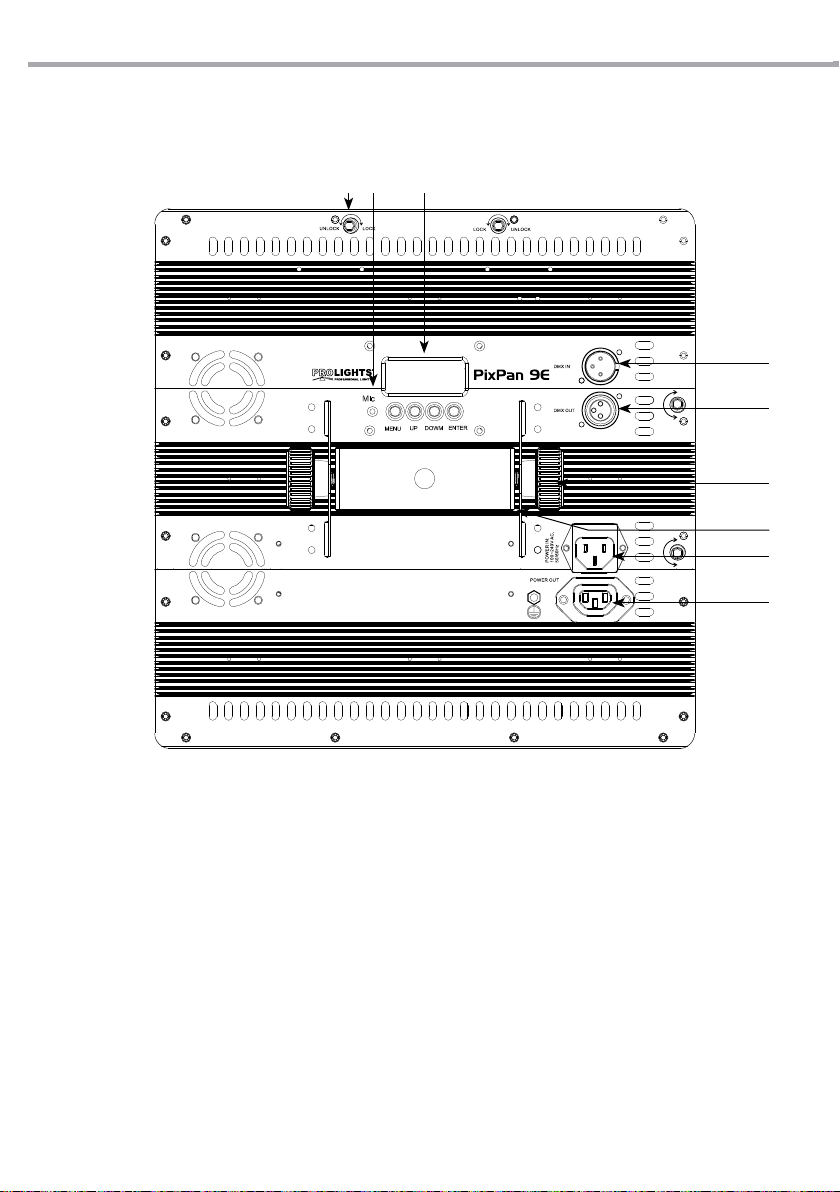
Rear view
1.3 OPERATING ELEMENTS AND CONNECTIONS
UNLOCK
LOC K
UNLOCK
LOC K
321
4
8
9
5
6
7
1. HOOK FIXING HOLE for mounting multiple
units in series
2. MICROPHONE to control the show by the
external audio signal.
3. CONTROL PANEL with display and 4 button
used to access the control panel functions
and manage them.
4. DMX IN (3-pole XLR):
1 = ground, 2 = DMX -, 3 = DMX +
5. DMX OUT (3-pole XLR):
1 = ground, 2 = DMX -, 3 = DMX +
6. LOCKING KNOB for the mounting bracket.
7. MOUNTING BRACKET
8. POWER IN mains plug for connection to a
socket (100-240V 50/60Hz) via the supplied
mains cable. The support for the mains fuse
is located near the mains plug. Only replace a
blown fuse by one of the same type.
9. POWER OUT or connection of multiple units
in series
Fig.1
5
PIXPAN 9E
- 2 - INSTALLATION
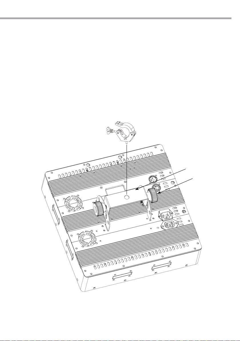
2.1 MOUNTING
PIXPAN9E may be set up on a solid and even surface. The unit can also be mounted upside down to a cross
arm. For xing, stable mounting clips are required. The mounting place must be of sucient stability and
be able to support a weight of 10 times of the unit’s weight.
When carrying out any installation, always comply scrupulously with all the regulations (particularly re-
garding safety) currently in force in the country in which the xture’s being used.
• Install the projector at a suitable location by means of the mounting bracket 3).
• Always additionally secure the projector with the safety rope from falling down. For this purpose, fas-
ten the safety rope at a suitable position so that the maximum fall of the projector will be 20 cm.
• Adjust the projector and use the knob (2) to slightly release or tighten the locking mechanism of the
bracket if is necessary.
CLAMP
Fig.2
2
3
PIXPAN 9E
6
Fig.3
- 3 - FUNCTIONS AND SETTINGS
3.1 OPERATION
Connect the supplied main cable to a socket (100-240 V~/50 Hz). Then the unit is ready for operation
and can be operated via a DMX controller or it independently performs its show program in succession.
To switch o, disconnect the mains plug from the socket. For a more convenient operation it is recom-
mended to connect the unit to a socket which can be switched on and o via a light switch.
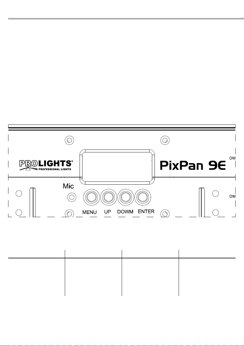
3.2 BASIC
Access control panel functions using the four panel buttons located directly underneath the LCD Display
(g.3).
MENU UP DOWN ENTER
Used to access the menu or
to return a previous menu
option
Navigates upward through
the menu list and increases
the numeric value when in a
function
Navigates downward
through the menu list and
decreases the numeric value
when in a function
Enables the currently
displayed menu or sets the
currently selected value in to
the current function
UNLOCK
LOCK
UNLOCK
LOCK

7
PIXPAN 9E
3.3 MENU STRUCTURE
MAIN FUNCTION SELECTION 1 SELECTION 2
AUTO SHOW P--
P 1
P 2
P 3
P 4
P 5
P 6
SPEED PROGRAM S-- S1 - S100
STATIC
C--
R
G
B
GB
RB
RG
RGB
U--
R=0-255
G=0-255
B=0-255
DMX CHANNELS
3--CH
5--CH
9--CH
27--CH
31--CH
SOUND MODE SNd
SOUND SENSITIVITY Sens U 1 - U 100
DIMMER Dim
O (speed o)
Dim 1 (speed fast)
Dim 2 (speed middle)
Dim 3 (speed slow)
FAN Fan auto
high
SEND DATA Send send 1
send 4
SLAVE MODE SLA
SLA 1
SLA 2
SLA 3
SLA 4

PIXPAN 9E
8
3.4 OPERATION IN AUTOMATIC MODE
If no DMX control signal is present at the DMX INPUT, the unit independently runs through its show pro-
gramme provided that the blackout mode is switched o:
• Press the button MENU so many times until the display shows [P--]
• Press the button UP/DOWN to switch between the programs (P1-P6), then press the button ENTER.
The unit will operate in automatic mode.
NOTE - Programs P1 - P6 are fully pre-programmed and will not be altered by changes in EDIT mode.
You can set the speed of execution of automated programs.
• Press the button MENU so many times until the display shows [S--]
• Using the button UP/DOWN, select the desired run speed (slow-fast) [S1 - S100].
• Press the button ENTER to conrm.
3.5 SOUND ACTIVE
• Press the button MENU so many times until the display shows [SNd],
• Press the button ENTER.
• You can set the microphone sensitivity pressing the button MENU so many times until the display show
[Sen]
• Using the button UP/DOWN, select the desired value sensitivity (slow-fast) [u0 - u100].
• Press the button ENTER to conrm.
3.6 MASTER/SLAVE MODE
This mode will allow you to link up the units together without a controller. Choose a unit to function as the
Master. The unit must be the rst unit in line; other units will work as slave with the same eect.
• Press the button MENU so many times until the display shows [SLA], and press the button ENTER to
conrm.
• Press UP/DOWN to set the unit as [SLA1-4].
• Select the desired program (see section 3.4).
• Use standard DMX cables to daisy chain your units together via the DMX connector on the rear of the
units. For longer cable runs we suggest a terminator at the last xture (see page 11).
3.7 LINKING
Several units may be interconnected in order to control all further slave units to the same eect of the
master unit.
1. Connect the DMX OUT of the master unit via 3 -pole XLR cable to the DMX IN of the rst slave unit.
2. Connect the DMX OUT of the rst slave unit to the DMX IN of the second slave unit, etc. until all units
are connected in a chain.
3.8 DMX CONFIGURATION
PIXPAN9E is equipped with 4 DMX conguration.
• Press the button MENU so many times until shows [dim], and press the button ENTER to conrm.
• Select the desired DMX conguration [3--CH/ 5--CH/ 9--CH/ 27--CH/ 31--CH] through the buttons UP/DOWN.
The tables on page 12 indicate the operating mode and DMX value. The PIXPAN9E is equipped with 3 pole
XLR connections.

9
PIXPAN 9E
3.9 DMX ADDRESSING
To able to operate the PIXPAN9E with a light controller, adjust the DMX start address for the rst a DMX
channel. If e. g. address 33 on the controller is provided for controlling the function of the rst DMX chan-
nel, adjust the start address 33 on the PIXPAN9E. The other functions of the light eect panel are then
automatically assigned to the following addresses.
An example with the start address 33 is shown below:
DMX512
Controller
. . . . . . . . . . . .
Number of
DMX channels
Start address
(example)
DMX Address
occupied
Next possible start
address for unit No. 1
Next possible start
address for unit No. 2
Next possible start
address for unit No. 3
9 33 33-41 42 49 56
31 33 33-63 64 95 126
Example 31 DMX channels configuration (31Ch mode)
Fig.4
DMX Address: 33 DMX Address: 126DMX Address: 64 DMX Address: 95
PIXPAN 9E
10
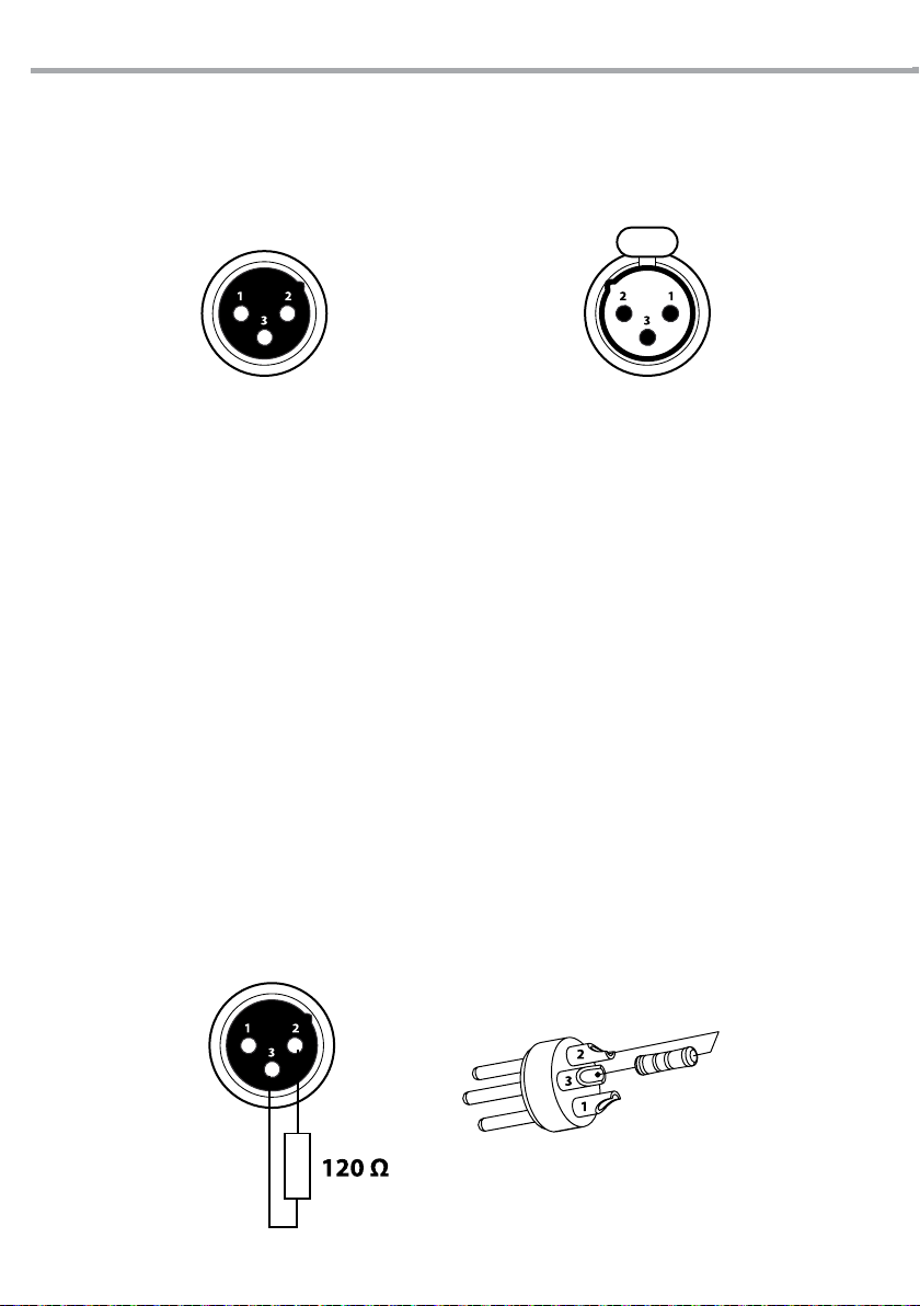
3.10 CONNECTION OF THE DMX LINE
DMX connection employs standard XLR connectors. Use shielded pair-twisted cables with 120Ω imped-
ance and low capacity.
The following diagram shows the connection mode:
ATTENTION
The screened parts of the cable (sleeve) must never be connected to the system’s earth, as this would
cause faulty xture and controller operation.
Over long runs can be necessary to insert a DMX level matching amplier.
For those connections the use of balanced microphone cable is not recommended because it cannot
transmit control DMX data reliably.
• Connect the controller DMX input to the DMX output of the rst unit.
• Connect the DMX output to the DMX input of the following unit. Connect again the output to the input
of the following unit until all the units are connected in chain.
• When the signal cable has to run longer distance is recommended to insert a DMX termination on the
last unit.
3.11 CONSTRUCTION OF THE DMX TERMINATION
The termination avoids the risk of DMX 512 signals being reected back along the cable when they reach-
es the end of the line: under certain conditions and with certain cable lengths, this could cause them to
cancel the original signals.
The termination is prepared by soldering a 120Ω 1/4 W resistor between pins 2 and 3 of the 5-pin male
XLR connector, as shown in gure.una resistenza di 120Ω (minimo 1/4W) tra i terminali 2 e 3, così come
indicato in gura.
DMX - OUTPUT
XLR socket
DMX - INPUT
XLR plug
Pin1 : GND - Shield
Pin2 : - Negative
Pin3 : + Positive
Fig.5
Esempio:
connettore XLR a 3 pin
Fig.6
11
PIXPAN 9E
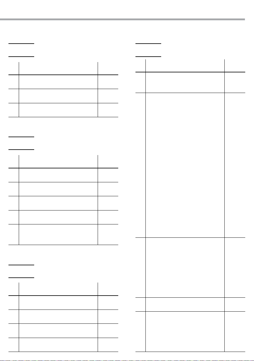
3.12 DMX CONTROL
Ch Function in 3 Ch mode Value
1RED
000 - 100% 000 - 255
2GREEN
000 - 100% 000 - 255
3BLUE
000 - 100% 000 - 255
Ch Function in 9 Ch mode Value
5
SHUTTER
No Function
Strobe Slow-Fast
000 - 010
011 - 255
6
MAN COLOR+COLOR TEMPERATURE
No Function
R 100% / G 0-100% / B 0%
R 100-0% / G 100% / B 0%
R 0% / G 100% / B 0-100%
R 0% / G 100-0% / B 100%
R 0-100% / G 0% / B 100%
R 100% / G 0% / B 100-0%
R 100% / G 0-100% / B 0-100%
R 100-0% / G 100-0% / B 100%
R 100% / G 100% / B 100%
Color temperature 1
Color temperature 2
Color temperature 3
Color temperature 4
Color temperature 5
Color temperature 6
Color temperature 7
Color temperature 8
Color temperature 9
Color temperature 10
Color temperature 11
000 - 010
011 - 030
031 - 050
051 - 070
071 - 090
091 - 110
111 - 130
131 - 150
151 - 170
171 - 200
201 - 205
206 - 210
211 - 215
216 - 220
221 - 225
226 - 230
231 - 235
236 - 240
241 - 245
246 - 250
251 - 255
7
AUTO PROGRAM
No Function
Chase 1
Chase 2
Chase 3
Chase 4
Chase 5
Chase 6
Sound
000 - 010
011 - 040
041 - 080
081 - 120
121 - 160
161 - 200
201 - 240
241 - 255
8AUTO SPEED
Speed Slow-Fast 000 - 255
9
DIMMER MODE
Menu setting dimmer mode
Dimmer mode OFF
Dimmer mode 1
Dimmer mode 2
Dimmer mode 3
000 - 051
052 - 101
102 - 152
153 - 203
204 - 255
Ch Function in 9 Ch mode Value
1DIMMER
0 - 100% 000 - 255
2RED
000 - 100% 000 - 255
3GREEN
000 - 100% 000 - 255
4BLUE
000 - 100% 000 - 255
Ch Function in5 Ch mode Value
1DIMMER
0 - 100% 000 - 255
2RED
000 - 100% 000 - 255
3GREEN
000 - 100% 000 - 255
4BLUE
000 - 100% 000 - 255
5
SHUTTER
No Function
Strobe Slow-Fast
000 - 010
011 - 255
3 Ch 9 Ch
9 Ch
5 Ch

PIXPAN 9E
12
Ch Function in 27 Ch mode Value
1RED 1
000 - 100% 000 - 255
2GREEN 1
000 - 100% 000 - 255
3BLUE 1
000 - 100% 000 - 255
4RED 2
000 - 100% 000 - 255
5GREEN 2
000 - 100% 000 - 255
6BLUE 2
000 - 100% 000 - 255
7RED 3
000 - 100% 000 - 255
8GREEN 3
000 - 100% 000 - 255
9BLUE 3
000 - 100% 000 - 255
10 RED 4
000 - 100% 000 - 255
11 GREEN 4
000 - 100% 000 - 255
12 BLUE 4
000 - 100% 000 - 255
13 RED 5
000 - 100% 000 - 255
14 GREEN 5
000 - 100% 000 - 255
15 BLUE 5
000 - 100% 000 - 255
16 RED 6
000 - 100% 000 - 255
17 GREEN 6
000 - 100% 000 - 255
18 BLUE 6
000 - 100% 000 - 255
Ch Function in 27 Ch mode Value
19 RED 7
000 - 100% 000 - 255
20 GREEN 7
000 - 100% 000 - 255
21 BLUE 7
000 - 100% 000 - 255
22 RED 8
000 - 100% 000 - 255
23 GREEN 8
000 - 100% 000 - 255
24 BLUE 8
000 - 100% 000 - 255
25 RED 9
000 - 100% 000 - 255
26 GREEN 9
000 - 100% 000 - 255
27 BLUE 9
000 - 100% 000 - 255
27 Ch

13
PIXPAN 9E
Ch Function in 31 Ch mode Value
1RED 1
000 - 100% 000 - 255
2GREEN 1
000 - 100% 000 - 255
3BLUE 1
000 - 100% 000 - 255
4RED 2
000 - 100% 000 - 255
5GREEN 2
000 - 100% 000 - 255
6BLUE 2
000 - 100% 000 - 255
7RED 3
000 - 100% 000 - 255
8GREEN 3
000 - 100% 000 - 255
9BLUE 3
000 - 100% 000 - 255
10 RED 4
000 - 100% 000 - 255
11 GREEN 4
000 - 100% 000 - 255
12 BLUE 4
000 - 100% 000 - 255
13 RED 5
000 - 100% 000 - 255
14 GREEN 5
000 - 100% 000 - 255
15 BLUE 5
000 - 100% 000 - 255
16 RED 6
000 - 100% 000 - 255
17 GREEN 6
000 - 100% 000 - 255
18 BLUE 6
000 - 100% 000 - 255
Ch Function in 31 Ch mode Value
19 RED 7
000 - 100% 000 - 255
20 GREEN 7
000 - 100% 000 - 255
21 BLUE 7
000 - 100% 000 - 255
22 RED 8
000 - 100% 000 - 255
23 GREEN 8
000 - 100% 000 - 255
24 BLUE 8
000 - 100% 000 - 255
25 RED 9
000 - 100% 000 - 255
26 GREEN 9
000 - 100% 000 - 255
27 BLUE 9
000 - 100% 000 - 255
28
AUTO PROGRAM
No Function
Chase 1
Chase 2
Chase 3
Chase 4
Chase 5
Chase 6
Sound
000 - 010
011 - 040
041 - 080
081 - 120
121 - 160
161 - 200
201 - 240
241 - 255
29 AUTO SPEED
Speed Slow-Fast 000 - 255
30 DIMMER
0 - 100% 000 - 255
31
SHUTTER
No Function
Strobe Slow-Fast 000 - 255
31 Ch

PIXPAN 9E
14
3.13 STATIC CONFIGURATION
For custom colors of device, is possible refer two modes of color management:
Fixture Color
• Press the button MENU so many times until show [C--] and press the button ENTER to conrm.
• Select the program (R - G - B - GB - RB - RG - RGB) through the button UP/DOWN.
• Press the button ENTER to conrm
Manual Color
• Press the button MENU so many times until show [U--] and press the button ENTER to conrm.
• Select the color red. green or blue (Red - Green - Blue)through the button UP/DOWN ad press the but-
ton ENTER.
• Set the value (000-255), through the button UP/DOWN.
3.14 SPECIAL FUNCTIONS
• Press the button menu and select through the directional buttons is possible to view to following func-
tions:
DIMMER
Enter [DIMMER MODE] to select dimmer mode and dimmer speed. When dimmer is set to [OFF], the RGB
and MASTER DIMMER are linear. The Dim1/2/3 are speed modes of the non linear dimmer, [dim1] is the
faster, while [dim3] is the slowest.
Note. The factory default setting is [dim3].
FAN SPEED
In [FAN SPEED] mode you can (optional) choose the speed rotation of the fan. You can select the desired
setting [AUTO] e [HIGH]

15
PIXPAN 9E
- 4 - MAINTENANCE
4.1 MAINTENANCE AND CLEANING THE UNIT
• Make sure the area below the installation place is free from unwanted persons during setup.
• Switch o the unit, unplug the main cable and wait until the unit has cooled down.
• All screws used for installing the device and any of its parts should be tightly fastened and should not
be corroded.
• Housings, xations and installation spots (ceiling, trusses, suspensions) should be totally free from any
deformation.
• The main cables must be in impeccable condition and should be replaced immediately even when a
small problem is detected.
• It is recommended to clean the front at regular intervals, from impurities caused by dust, smoke, or
other particles to ensure that the light is radiated at maximum brightness. For cleaning, disconnect the
main plug from the socket. Use a soft, clean cloth moistened with a mild detergent. Then carefully wipe
the part dry. For cleaning other housing parts use only a soft, clean cloth. Never use a liquid, it might
penetrate the unit and cause damage to it.
4.2 FUSE REPLACEMENT
1. Remove the safety cap by a screwdriver.
2. Replace the blown fuse with a fuse of the exact same type and rating.
3. Install the safety cap, and reconnect power.
4.3 TROUBLESHOOTING
Problems Possible causes Checks and remedies
Fixture does not light up
• No mains supply
• Dimmer fader set to 0
• All color faders set to 0
• All colors in STATIC are seto to 0
• Faulty LED
• Faulty LED board
• Check the power supply voltage
• Increase the value of the dimmer channels
• Increase the value of the color channels
• Increase the values og the colors
• Replace the LED board
• Replace the LED board
General low light intensity • Dirty lens assembly
• Misaligned lens assembly
• Clean the xture regularly
• Install lens assembly properly
Fixture does not power up
• No power
• Loose or damaged power cord
• Faulty internal power supply
• Check for power on power outlet
• Check power cord
• Replace internal power supply
Fixture does not respond to DMX
• Wrong DMX addressing
• Damaged DMX cables
• Bouncing signals
• Check control panel and unit addressing
• Check DMX cables
• Install terminator as suggested
Contact an authorized service center in case of technical problems or not reported in the table can not be
resolved by the procedure given in the table.

PIXPAN 9E
2
REV.001-05/13
Music & Lights S.r.l. si riserva ogni diritto di elaborazione in qualsiasi forma delle presenti istruzioni per l’uso.
La riproduzione - anche parziale - per propri scopi commerciali è vietata.
Al ne di migliorare la qualità dei prodotti, la Music&Lights S.r.l. si riserva la facoltà di modicare, in
qualunque momento e senza preavviso, le speciche menzionate nel presente manuale di istruzioni.
Tutte le revisioni e gli aggiornamenti sono disponibili nella sezione 'Manuali' sul sito www.musiclights.it

3
PIXPAN 9E
• PIXPAN9E
• Cavo di alimentazione
• Staa di ssaggio
• Manuale utente
Contenuto dell'imballo:
INDICE Sicurezza
Avvertenze generali
Attenzioni e precauzioni per l’installazione
1 Introduzione
1. 1 Descrizione
1. 2 Speciche tecniche
1. 3 Elementi di comando e collegamenti
2 Installazione
2. 1 Montaggio
3 Funzioni e impostazioni
3. 1 Funzionamento
3. 2 Impostazione base
3. 3 Struttura menu
3. 4 Funzionamento in modalità automatica
3. 5 Funzionamento in modalità musicale
3. 6 Modalità Master/Slave
3. 7 Collegamento
3. 8 Congurazioni canali DMX
3. 9 Indirizzamento DMX
3. 10 Collegamenti della linea DMX
3. 11 Costruzione del terminatore DMX
3. 12 Tabella canali DMX
3. 13 Congurazione Static
3. 14 Funzioni speciali
4 Manutenzione
4. 1 Manutenzione e pulizia del sistema ottico
4. 2 Sostituzione fusibile
4. 3 Risoluzione dei problemi
4
4
5
5
6
7
8
8
9
10
10
10
10
10
11
12
12
13
16
16
17
17
18
PIXPAN 9E
4
ATTENZIONE! Prima di effettuare qualsiasi operazione con l’unità, leggere con attenzione
questo manuale e conservarlo accuratamente per riferimenti futuri. Contiene informazioni
importanti riguardo l’installazione, l’uso e la manutenzione dell’unità.
SICUREZZA
Avvertenze generali
• I prodotti a cui questo manuale si riferisce sono conformi alle Direttive della Comunità Europea e per-
tanto recano la sigla .
• Il dispositivo funziona con pericolosa tensione di rete 230V~. Non intervenire mai al suo interno al di
fuori delle operazioni descritte nel presente manuale; esiste il pericolo di una scarica elettrica.
• È obbligatorio eettuare il collegamento ad un impianto di alimentazione dotato di un’eciente messa
a terra (apparecchio di Classe I secondo norma EN 60598-1). Si raccomanda, inoltre, di proteggere le
linee di alimentazione delle unità dai contatti indiretti e/o cortocircuiti verso massa tramite l’uso di
interruttori dierenziali opportunamente dimensionati.
• Le operazioni di collegamento alla rete di distribuzione dell’energia elettrica devono essere eettuate
da un installatore elettrico qualicato. Vericare che frequenza e tensione della rete corrispondono alla
frequenza ed alla tensione per cui l’unità è predisposta, indicate sulla targhetta dei dati elettrici.
• L’unità non per uso domestico, solo per uso professionale.
• Evitare di utilizzare l’unità:
- in luoghi soggetti a vibrazioni, o a possibili urti;
- in luoghi a temperatura superiore ai 45°C o inferiori a -5°C.
• Evitare che nell’unità penetrino liquidi inammabili, acqua o oggetti metallici.
• Non smontare e non apportare modiche all’unità.
• Tutti gli interventi devono essere sempre e solo eettuati da personale tecnico qualicato. Rivolgersi al
più vicino centro di assistenza tecnica autorizzato.
• Se si desidera eliminare il dispositivo denitivamente, consegnarlo
per lo smaltimento ad un’istituzione locale per il riciclaggio.
Attenzioni e precauzioni per l’installazione
• Questo prodotto è solo per uso interno. Per prevenire il rischio di incendi o scosse elettriche, non espor-
re il prodotto alla pioggia o all’umidità.
• Se il dispositivo dovesse trovarsi ad operare in condizioni dierenti da quelle descritte nel presente
manuale, potrebbero vericarsi dei danni; in tal caso la garanzia verrebbe a decadere. Inoltre, ogni altra
operazione potrebbe provocare cortocircuiti, incendi, scosse elettriche, rotture etc.
• Prima di iniziare qualsiasi operazione di manutenzione o pulizia sull’unità togliere la tensione dalla rete
di alimentazione.
• È assolutamente necessario proteggere l’unità per mezzo di una fune di sicurezza. Nell’eseguire qualsiasi in-
tervento attenersi scrupolosamente a tutte le normative (in materia di sicurezza) vigenti nel paese di utilizzo.
• Installare l’unità in un luogo ben ventilato.
• Mantenere i materiali inammabili ad una distanza di sicurezza dall’unità.
• I ltri, le lenti o gli schermi ultravioletti se danneggiati possono limitare la loro ecienza.
• I LED devono essere sostituiti se danneggiati o termicamente deformati.
• Non guardare direttamente il fascio luminoso. Tenete presente che i veloci cambi di luce possono pro-
vocare attacchi d’epilessia presso persone fotosensibili o epilettiche.
• La distanza minima tra il proiettore e le pareti circostanti deve essere superiore a 50 cm e non devono
essere ostruite, in nessun caso, le aperture d’aerazione.
• L’unità deve essere posizionata in modo tale che gli oggetti colpiti dal fascio luminoso siano distanti
almeno 0.1 m da essa.
• Tenere l’unità lontana dalla luce diretta del sole.
• Per la pulizia del prodotto non usare solventi per non danneggiare la nitura esterna.
Table of contents
Languages:
Other Tribe Lighting Equipment manuals


Popular Lighting Equipment manuals by other brands

Vision & Control
Vision & Control LDLF30x300-B470/24V/-a Instructions for use

Zodiac
Zodiac Hydroxinator iQ Series Instructions for installation and use

DÖRR
DÖRR SL-480 instruction manual

Showline
Showline SL PUNCHLITE 220 Installation and user manual

Goobay
Goobay 96500 user manual

Astrapool
Astrapool NET ‘N’ CLEAN 26985 Installation


