Tricel Vitae UK6 User manual

1
206 Rev 3 Jan 2019
Tricel® Vitae UK6
Wastewater Treatment Plants
Engineering a green future

2
Contents
1Health & safety precautions ......................................................................................................4
1.1 General..............................................................................................................................4
1.2 Electrical maintenance......................................................................................................4
1.3Installation ........................................................................................................................ 5
2Introduction: Tricel Vitae...........................................................................................................6
2.1 The Wastewater purification process................................................................................6
Stage 1: Buffer chamber ................................................................................................6
Stage 2: Aeration (treatment) chamber.........................................................................6
3Tricel Vitae specification...........................................................................................................7
3.1 Dimensions .......................................................................................................................7
3.2 Tank drawing.....................................................................................................................8
4Transportation & lifting.............................................................................................................9
4.1 Transportation .................................................................................................................. 9
4.2 Lifting................................................................................................................................9
5
Installation
.............................................................................................................................11
5.1 Installation planning .......................................................................................................11
5.2 Inspection on reception of tanks.....................................................................................12
5.3 Positioning and precautions............................................................................................12
5.4 Types of installation........................................................................................................12
5.5 Installation procedure: Tricel Tanks................................................................................13
Excavation (dry & wet sites): .......................................................................................13
Step by step – installation procedure ..........................................................................15
5.6 Gravel specification ........................................................................................................16
5.7 Concrete specification ....................................................................................................17
5.8 Topsoil requirements......................................................................................................17
5.9 Electrical requirements...................................................................................................17
5.10 Risers ..............................................................................................................................18
5.11 Non-standard ..................................................................................................................18
Alternative to concrete backfill (for wet sites without risers only):
...................18
Sloping ground: .......................................................................................................19
Proximity to rolling & static loads: ..........................................................................19
5.12 Additional accessories ....................................................................................................20
Grease trap ..............................................................................................................20
Sampling chamber...................................................................................................20
6Capsule installation.................................................................................................................21

3
7Commissioning ........................................................................................................................21
7.1 Control panel start-up.....................................................................................................22
7.2 Operation of the control panel........................................................................................24
Basic screen display.....................................................................................................24
Start-up phase ‘Start 150%.’.......................................................................................25
8Disposal of treated water ........................................................................................................26
9Maintenance ............................................................................................................................26
9.1 Regular maintenance ......................................................................................................26
9.2 Annual maintenance........................................................................................................26
9.3 Annual service(available from your supplier) .................................................................27
9.4 Production of sludge .......................................................................................................27
9.5 Desludging (emptying the solid waste from the primarychamber) ................................27
10 Operating conditions ..........................................................................................................28
11 Troubleshooting..................................................................................................................30
11.1 Odours.............................................................................................................................31
12 Certification........................................................................................................................32
12.1 Declaration of performance ............................................................................................32
13 Terms & conditions .............................................................................................................36

4
1Health & safety precautions
Reading the full technical manual prior to installation is important. Retain this document for the
lifetime of the product and in the event of a change of ownership of the site, transfer to the new
owner.
As health and safety are of vital importance, the following aspects are critical:
Precaution
Prior to installing, please consider the finished garden level. If you envisage that a
manholeriser/extensionmay be requiredto ensure manholecover remainsabove finished
ground level, the plant must be installed with the appropriateexcavationfoundationand
backfilltoaccommodatethe riser. Please refer to section 5.10, ‘Risers.’
1.1
General
•
It is important that all of the information contained in this manual be adhered to at
all times.
•
Treatedwastewaterisnotsuitableforhumanconsumption.
•
It is importantthatlocksbefittedto the manhole cover to preventaccidental access.
•
Manholes are ratedto125kgand are for pedestrianuseonly.
•
Neverenteratankunless qualifiedtodoso.
•
Do not use naked flames in the vicinityof the tank due tothe danger of combustion.
•
The manhole covers shall never be left off of an unattended tank. Always lock the
covers of the plant when work gets completed.
•
Sewage and sewage effluent can carry micro-organisms and gases harmful to human
health. Any person carrying out work on the
Vitae
must be appropriately trained.
•
Suitable protective clothing; including gloves, goggles should be worn at all times.
Always remove contaminated clothing and protective equipment after working with
sewage treatment plants.Wash handsand face prior to eating, drinkingorsmoking.
•
Lock all manhole covers for safety. Tanks are supplied with three locking points, as
shown below. All points should be locked with a suitable locking device to prevent
unauthorised access. Locks do not come supplied.
1.2
Electrical maintenance
•
All electrical work is to be carried out by a qualified electrician using suitable
materials for the application.
•Do not open the Tricel Vitae’s electrical unit cover without firstly isolating the mains
power.
•
Electrical work must be carried out strictly to the manufacturer’s instructions and to
the relevant national rules for electrical installations.
•
When working with machinery/electrical equipment, the proximity of water shall be
noted. Electrical equipmentshall not be wet when working with it.
•
There is the potential danger of falling into the tank during desludging while manholes
may be open – take all necessary safety precautions when desludging.

5
1.3
Installation
•
Plan excavationworkwithdueregardtohealth andsafetyrequirements.
•
Excavated material should either beshored or battenedbackto a“safe”angle.
•
Use appropriate liftingequipment.
•
Take carearoundgroundsworkmachinery.
•
Keepproper footing and balance at all time.
•
It is necessary to vent the Tricel Vitae at the inlet and the outlet of the plant.
6
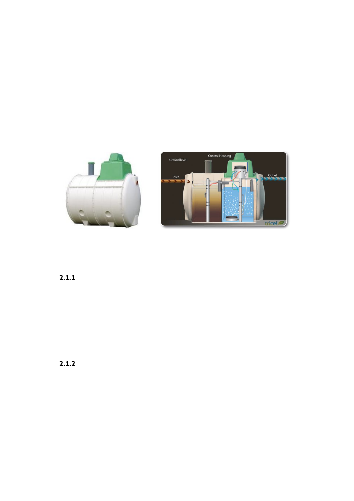
2Introduction: Tricel Vitae
Tricel Vitae wastewater treatment plants are manufactured from sheet moulding compound (SMC)
ensuring a durable and high-strength product. They are also constructed from modular
components; these modules are then fabricated together to make different size tanks.
The Tricel Vitae is suitable for domestic and light commercial applications and is a sequential batch
reactor (SBR). There are two zones in the SBR treatment system. The first is a buffer zone where the
wastewater gets stored. From here it is carried into the second zone for treatment in batches.
Wastewater is then treated for a set amount of time, after which it is expelled from the tank. As the
treatment is for a fixed amount of time in each batch, the water emitted from the tank is to the
highest quality standard even in times of high usage
.
2.1
The Wastewater purification process
Stage 1: Buffer chamber
The buffer chamber acts primarily as a storage zone to hold the wastewater until it is ready to be
treated. This ensures that even in times of low usage there is a constant supply of wastewater to
feed the bacteria. While being stored the heavy solids settle to the bottom of the tank and the light
particles, like fats or oils, float to the top of the water to create a scum. An airlift pump takes
wastewater from the buffer chamber to the aeration chamber in batches at the beginning of the
aeration cycle. The airlifter is designed to ensure that only the wastewater from the centre of the
chamber gets transferred into the aeration chamber.
Stage 2: Aeration (treatment) chamber
This stage of the process takes place in the second chamber where submerged aeration combines
the principles of the biofilm and activated sludge processes. Masses of naturally occurring bacteria
form in clumps at the bottom of the chamber. These bacteria get sustained with air delivered by
means of an aerator at the bottom of the tank which turns on intermittently throughout the cycle.
After the aeration takes place, there is a settling phase in which the aerator is turned off for 1.5 -2
hours. This process allows for the solids and the bacteria to settle to the bottom of the chamber. As
a result, the water above is cleared of any solid particles before it gets expelled from the tank.

7
During the settlement phase, the batch of liquid is kept in this chamber for a set amount of time
and then expelled from the tank using the clearwater lifter. Simultaneously, the excess sludge
lifter recirculates the excess sludge from the tank back to the primary chamber. Doing so ensures
that there is a constant level of sludge in the primary chamber to feed into the aerated zone.
The clearwater enters the sampling pot before leaving the tank. Doing so allows for the water to
get tested for purity. The remaining treated liquid now meets the required standard to be safely
passed out of the Tricel Vitae unit.
3Tricel Vitae specification
3.1
Dimensions
Tricel Vitae: certified to EN 12566-3:2005
Tricel Vitae
UK6
Maximum treatment capacity
PE
6
Design flow rate (max)
litres/day
900
BOD load (max)
kg/day
0.36
Primary chamber volume
litres
2630
Nominal Inlet pipe diameter
mm
110
Nominal Outlet pipe diameter
mm
110
Overall length
m
2.6
Overall width
m
1.64
Overall height
m
2.24
Inlet invert to base
m
1.4
Outlet invert to base
m
1.3
Inlet invert to ground level
m
0.51
Outlet invert to ground level
m
0.61
Weight empty**
kg
300
No. of persons
1-6
Air blower rating (mean)
W
86
Thickness (minimum)
mm
5
Desludge period (minimum)***
year
1.5 – 3
No. of Diffusers
Units
1
** Allow 100kg extra for lifting purposes
*** Depending on use & design value
8
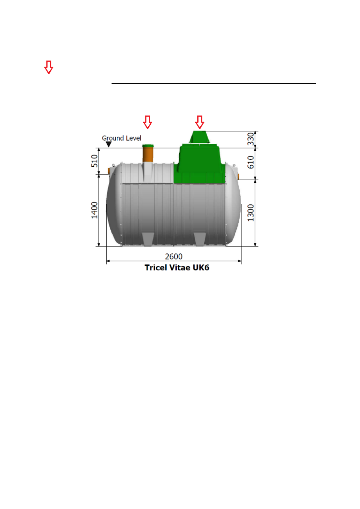
3.2
Tank drawing
The arrow indicates an access point which must be opened to facilitate the desludging of the
primary chamber. However, do not desludge the reactor/aeration chamber as this will affect
the treatment efficiency of the plant.
WARNING: care must be taken not to damage pipework when desludging the tank

9
4Transportation & lifting
4.1
Transportation
•
Tanks must be held down during transportation using nylon straps, do not use cables or
chains to secure tanks. Do not over tighten straps that can result in deformation of the
tank shell. Do not drop or roll tanks from the truck.
•
Move tanks only by lifting and setting, do not drag or roll.
•
Always set the tank(s) on flat, smooth ground clear of debris. In order to prevent
movement, tanks may need to be tied down and chocked. Position the chocks in the
locations shown below:
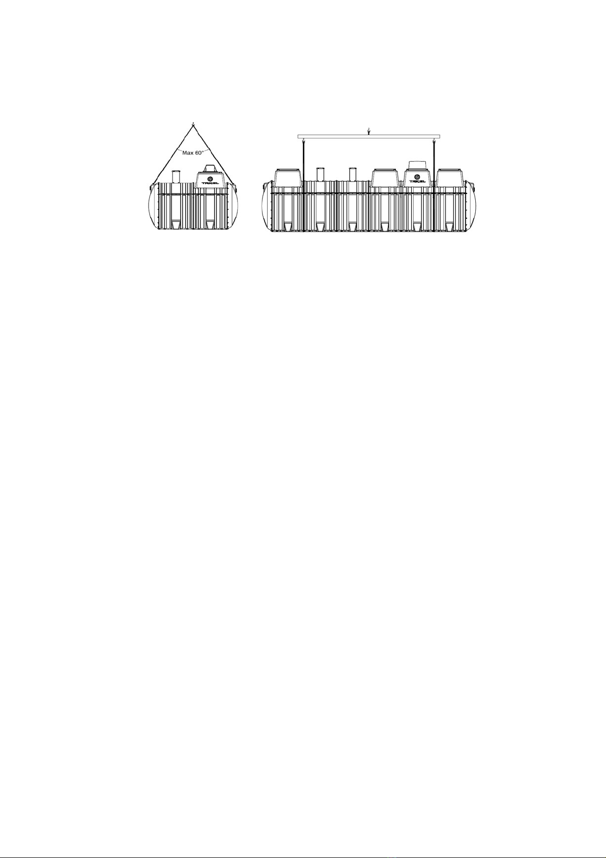
4.2
Lifting
•
A machine and webbing lifting straps best lift tanks – do not use chains or wire ropes in
contact with the tank.
•
Ensure tank is empty when lifting.
•
Tanks from one to four modules (4.6m) in length should be lifted using the eyebolts on
the tank. Ensure the angle between the slings is not greater than 60o when lifting the
tank. In order to ensure the angle is not greater than 60o the following sling lengths
are required:
Length of tank
Minimum length of the
sling
2.1
2.1
2.6
2.6
3.1
3.1
3.6
3.6
4.6
4.6
10
Ensure sufficient lifting height can be achieved and is available on site. If not a lifting bar, as per
option two below, is required.
Option 1 Option 2

11
5
Installation
5.1
Installation planning
Important
Before the installation of the Tricel Vitae, it is important to read these instructions carefully.
•When planning the installation of a Tricel Vitae, you must consider the following:
Backfill considerations:
oIs this a dry or wet site, i.e. the presence of a water table?
oWhich backfill material is appropriate for this site?
oWhat will the finished ground level be and will risers be required?
Site considerations:
oIs the site restricted regarding area or height?
oWhat is the topography of the site, i.e. being it sloping or flat?
oWhat is the proposed depth of the installed tank to ensure the required slope
upstream?
oAre static or rolling loads present on this site?
•Only suitably qualified personnel should install the Tricel Vitae.
•
Suitably sized equipment will be required to excavate the hole and to lift the
Tricel
Vitae
into place.

12
5.2
Inspection on reception of tanks
•
Visually inspect tanks for damage or fractures to the shell or ribs, de-laminations,
scratches, or abrasions deeper than 1.5mm, which may have occurredduringtransport,
prior to installation.Notify the delivery driver and/or your supplier of any found.Do not
attempt to carry out any unauthorisedrepairs, as this will invalidate the warrantyon the
tank.
•
Onceinstalled,Tricelcannotacceptanyclaimsfordamage to the tank.
5.3
Positioning and precautions
•The Tricel Vitae should not get installed in an area subject to flooding or excessive water
runoff as no flood waters should enter the tank.
•The area around the Tricel Vitae should be adequately drained to permanently remove
groundwater and surface water from proximity to the tank.
•The Tricel Vitae is not suitable to be used in water-logged sites where the groundwater
may rise above the inlet pipe.
•When selecting the location of the Tricel Vitae, ensure that it is always accessible for future
maintenance.
•The Tricel Vitae must be vented at the outlet and the inlet of the plant.
5.4
Types of installation
All installations must be “fit for purpose” to suit the on-site conditions, which will vary from site
to site. Ensuring this is the responsibility of the on-site contractor.
When installing a Tricel Vitae, there are two types of standard installation methods:
1. Gravel installation
2. Concrete installation
It is essential to consider two factors when determining which installation must be implemented:
1. Is the Tricel Vitae being installed in a ‘dry site’ or a ‘wet site’?
•A ‘dry site’ is a site in which the water table never rises higher than the base of
the tank.
•A ‘wet site’ is a site in which the water table may rise higher than the base of
the tank but will not climb higher than the invert of the inlet. Where a higher
water level is present on site, ensure that the installation is suitable for the site
conditions.
Tricel
strongly advises the installation of a vertical water table inspection pipe.
This inspection pipe will facilitate convenient monitoring of the water table
long after the installation is complete.
Note: In difficult soils (e.g., clay with a high t-value), a site could be potentially
classified as wet if there is no drainage for surface water that enters the

13
excavation and it rises higher than the base of the tank. The installer must
determine this when selecting the correct backfill.
2. Is a riser required (inlet invert >510mm from ground level), and if yes, what height riser
is necessary? (For more information on risers, please refer to section 5.10, ‘Risers’).
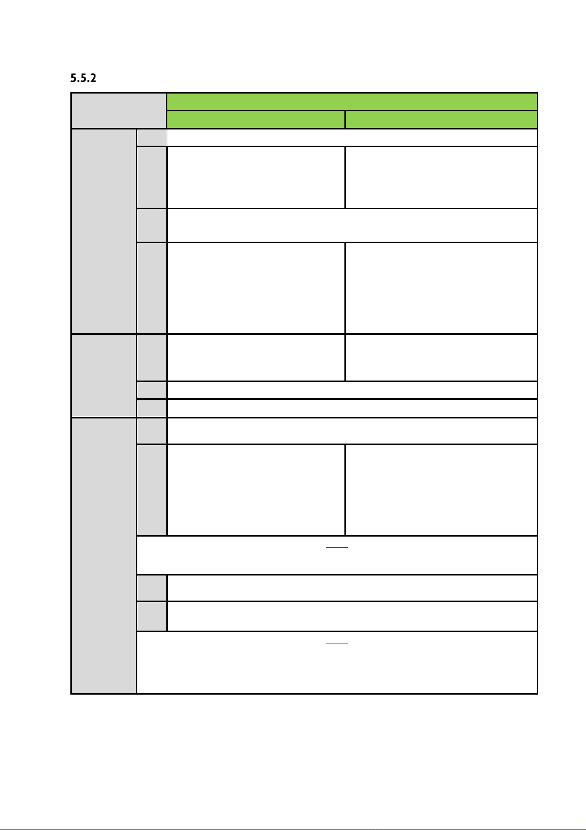
The following table specifies the required installation for on-site conditions:
Factors that determine the required installation
Installation required
Type of site
Riser required
Dry
None
Gravel
Dry
250mm
Gravel
Dry
500mm & 750mm
Concrete
Wet
None
Concrete
Wet
250mm, 500mm & 750mm
Concrete
Important
•
Incorrectly installed tanks that are subject to movement, rotation, excessive loading
or floatation may become damaged, for which Tricel cannot accept liability.
•
During installation, tanks must not be subjected to buoyant forces.
•
Contact a qualified engineer if there are difficulties on site due to adverse
waterlogging.
•
Ballasting the tank is essential to avoid the tank from lifting when backfilling.
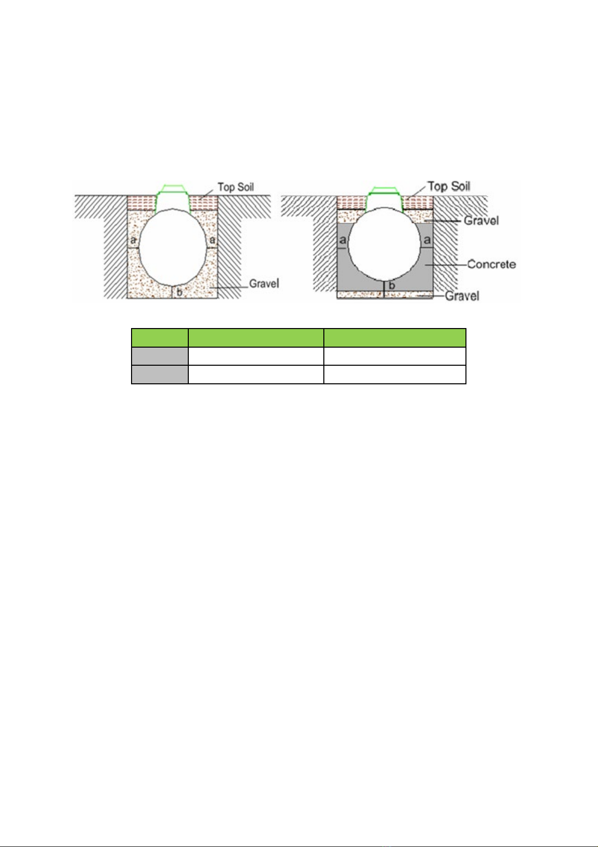
5.5
Installation procedure: Tricel Tanks
Excavation (dry & wet sites):
5.5.1.1
Excavation: length & width
Length and width of the excavation must exceed the dimensions of the
Tricel Vitae
by at least
500mm to maintain a minimum space of 250mm all around the tank.
Tricel Vitae UK6
Tank length (m) 2.6
Tank width (m) 1.64
Excavation size (L x W) (m) 3.1 x
2.14
Note: The size of the area for excavation applies to both dry and wet sites. However,
unstable
ground including regions with excessive sand, peat swamps, etc., may require larger
excavations.Theexcavation should be maintained dryby pumpingor whatever suitable means.
14
5.5.1.2
Excavation: depth
The inlet and outlet pipes determine the excavation depth, invert levels are relative to the
bottom of the tank and allowing for the minimum base thickness. Dimensiondetails of the tank
provided on the relevant drawing; please refer to section 3, ‘Tricel Vitae Specification.’ Ground
instability, e.g. running sand may necessitate over-excavation and stabilisationwith hard core
or blinding concrete. The standard depth of the excavation for both gravel and concrete
installations are outlined as follows:
“a” minimum (mm)
“b” minimum (mm)
Dry site
250
250
Wet site
250
300
15
Step by step – installation procedure
Steps
Installation required (post-excavation)
Gravel
Concrete
Installation
of the tank
base:
1
Remove any soft spots or large stones and boulders.
2
The base is constructed of a 250mm
layer of suitably compacted gravel.
The base is constructed of a 50mm layer
of suitably compacted gravel, covered
with a 250mm layer of semi-dry
concrete.
3
Ensure that base is level and at the correct height to accommodate the
incoming pipework.
4
It is important to maintain a completely
dry excavation until the final pour of
concrete is set. It may be necessary to
line the excavation with a continuous
layer of 1200-gauge polythene to
maintain the integrity of the concrete.
How to
position the
tank on to
the base:
5
Mechanically lift the plant carefully
into the centre of the hole and place
on the prepared base.
Mechanically lift the plant carefully
into the centre of the hole.
6
The plant must sit level on the base.
7
Connect and seal the pipework to the tank.
Backfilling
around the
tank:
8
Ballast the plant by filling each chamber with clean water to a depth of 300mm
and recheck the pipework levels.
9
Commence backfilling with gravel in
layers of 225mm evenly around the
tank ensuring that there are no voids
until gravel has reached 50mm over
the cylindrical body of the tank.
Compact each layer in succession. *
Commence backfilling with concrete in
layers evenly around the tank, ensuring
that there are no voids until it has
reached the outlet invert. Continue
backfilling with gravel, until it has
reached 50mm over the cylindrical
body of the tank. *
Note
* Continue filling the chambers with water while backfilling, ensure that the rising
water level is no more than 300mm above the backfill level.
10
Mount and seal manhole risers (if required). Please refer to section 5.10,
‘Risers.’
11
Complete backfilling with topsoil up to the max ground level. Allow for
subsequent settlement of topsoil.
Note
The use of geotextile barrier fabrics over the gravel backfill is considered good
installation practice. The fabric must be chosen to allow the flow of water in and
out of the excavation but to prevent the movement of fine soil particles into the
gravel backfill.
16
5.6
Gravel specification
Primary backfill specification:
•
Primary backfill material should be free-flowing granular material.
•
Compaction should be by lightweight rollers or vibratory plate. Compact gravel evenly
to ensure proper support for the tank. Make sure the vibrating machine does not come
in contact with the shell of the tank.
•
Tanks installations require primary backfill only within the region immediately
surrounding the tanks. Thisbackfill must extend a minimum of250mmoutward fromthe
tank, and directlybeneaththe tank.
•Backfill material shall not be frozen or contain lumps of frozen material at any time during
installation.
•Use of other than specified backfill and bedding materials will void the tank warranty.
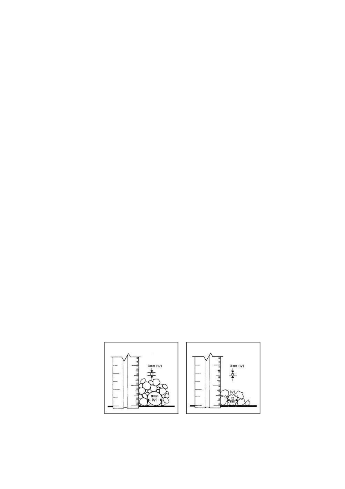
The following materials are approved as primary backfill:
Rounded pea gravel:
•
Minimum particle size 3mm, maximum 18 mm, compacted to a relative density of
>70%.
•
Gravel shall be clean and free flowing, free from large rocks, dirt, sand, roots, organic
materials or debris.
•
Upon screening analysis, the backfill material shall have no more than 5% by weight
passing 2.36 mmsieve.
Or
Crushed or processed stone:
•
Minimum particle size 3 mm, maximum 12 mm, compacted to a relative density of
>40%.
•Dry gravel density must be at least 1500 kg/m3. The material should be washed or screened
to remove fine particles.
•Upon screening analysis, the backfill material shall have no more than 5% by weight
passing a 2.36 mm sieve.
Pea Gravel Crushed Stone

17
5.7
Concrete specification
Semi dry concrete 25n grade with a ratio of 4.5 aggregate to 1 cement.
Important:
•
Do not use standard concrete mixes where sulphates or similarly aggressive chemicals
are present in the groundwater.
•
Lift height (rate of rise): Determine the lift height (m), or rate of rise (m/h) for the
specific, concrete type used, to ensure that a design pressure (P max) of 15kN/m2 on the
tank does not get exceeded.
•
Vibration: The tank design assumes minimal compaction of the surrounding concrete.
Where necessary, this may be extended to include internal light vibration. Never use
deep revibration which will substantially increase the pressure on the tank, possibly
causing failure.
•
Impact of concrete on discharge: Under no circumstances should concrete be discharged
directly onto the tank.
5.8
Topsoil requirements
Clean native topsoil shall not contain rocks larger than 36mm on largest dimension.
5.9
Electrical requirements
Important
•
Please ensure the electrical installation complies with all national regulations and
requirements
.
•
Electrical installations must be carried out by a qualified
and certified electrician.
•
Please note different electrical requirements are dependant on the size of the Tricel
Vitae system, read the following sections carefully.
T
he customers’ minimum responsibility shall consist of:
•
A single run of 1.5mm² three core (two conductors plus earth conductor) steel wire
armoured (SWA) cable from the customer’s distribution cabinet to the tank unit socket
box.
•
Cableprotectionvia10-ampMCBprotectedby(RCD),rated230V,30mA.
•
Bond thecablearmourproperly to themainearth at the premises.
•
Never disconnectthe power to the air pump. It is imperative that it be running 24 hours a
day,everyday.
18
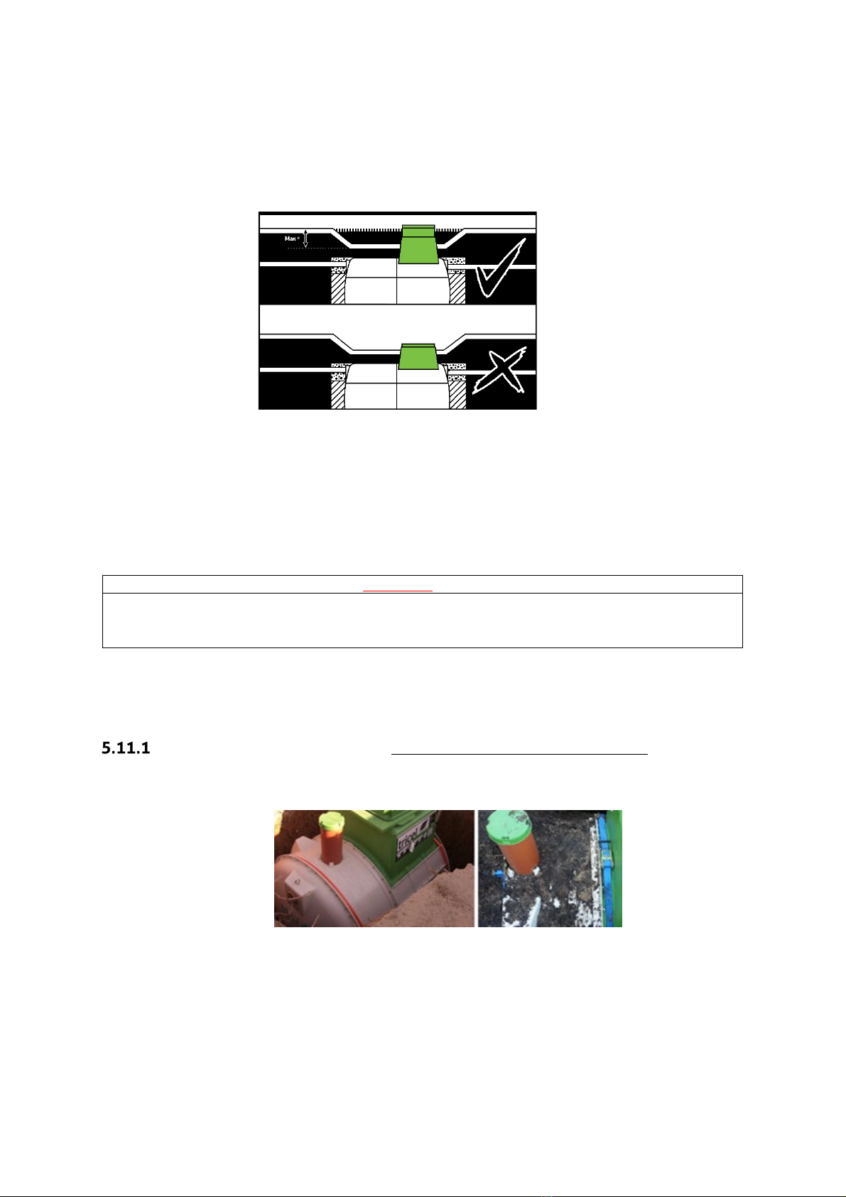
5.10
Risers
In the event that a Tricel Vitae requires a deeper than standard installation to align with the
wastewater outlet from the premises, manhole risers are available. These are to avoid the
access cover being positioning in a depression, as shown in the following diagram:
•
250mm, 500mm, and 750mm risers are available for the Tricel Vitae if required
(requires installation suitable for the site conditions, please refer to section 5.4,
‘Types of installation’).
•
TheTricelVitae issuitableforamanholeriserwhich givesa maximuminletinvertof
1260mm
. However, the Tricel Vitae is not suited to areas where a more in-
depth installation is necessary.
Important:
•Never place the manhole covers below ground level.
•Only use
Tricelmanhole covers and risers.
•
Do not allow ground water to enter the plant.
5.11
Non-standard
Alternative to concrete backfill (for wet sites without risers only):
•
The option of securing the Tricel Vitae to a reinforced concrete slab or Deadman anchor by
way of straps may also be applied, as shown below:
•
Tricel accepts no responsibility for the design of the concrete slab/Deadman
anchor. This solution should bedesigned byan on-sitestructuralengineerto suitsite
conditions.
•
If implemented, position the straps as close to the bolted joints as possible.

19
Sloping ground:
When the slope of the ground is 5% or more, it is recommended to install a retaining wall to protect
the tank from the lateral thrust. Concrete backfill may also in some cases be sufficient to protect
the tank. A qualified structural engineer must determine if a retaining wall is required in the
presence of a steep slope as shown in the picture below:
Proximity to rolling & static loads:
Minimum separation distances from:
•Rolling loads (e.g., vehicle traffic): 4 metres
•Static loads (e.g., dwelling house, shed): 3 metres
If the tank installation is in an area where traffic or other superimposed loadings can be
applied, consult a structural engineer for the design of a reinforced concrete slab to prevent
any load getting transferred to the tank (or its concrete surround). If this slab is constructed
immediately above the tank, separate it from the surrounding concrete by a compressible
material.

20
5.12
Additional accessories
Grease trap
•Best practice indicates that a grease trap gets fitted before the
TricelVitae, particularly in
applications where high quantities of grease/oil exist in the wastewater.
•
For the grease trap tp continue to perform effectively, it must be
monitored/maintained on a regular basis and emptied when required.
Warning
If high levels of grease/oil are present within the Tricel Vitae, the plant will not
achieve the required treatment quality and it will reduce the lifespan of plant
components.
Sampling chamber
•
Best practice indicates that a sampling chamber is fitted after every
Tricel Vitae
to allow
easy access for sampling purposes.
•Care should be taken to ensure that the sampling apparatus does not come into contact with
the pipework or walls of the sampling chamber to avoid contamination of the sample.
•
Ensure that the outlet is installed high enough in the sampling chamber to allow for the
required sampling volume to be retained in the bottom of the sampling chamber.
•The inlet/outlet pipework installed in the sampling chamber must be minimum diameter of
110mm.
Table of contents
Popular Other manuals by other brands

Barska
Barska AX11646 user manual

Custom Dynamics
Custom Dynamics GEN200-KIT-1157 Installation instructions manual

Invengo
Invengo XC2600 user manual

Orla
Orla GT5000 owner's manual

Westfalia
Westfalia 303 164 installation instructions

Whelen Engineering Company
Whelen Engineering Company Outer Edge Pillar Mount LC Lightbar Installation guides


Parker
Parker Sporlan SMART Pro/R quick start guide

Duncan
Duncan STK-S4 Classic Stack Plus Wiring diagram

ATS
ATS Allison Transmission Pan kit installation manual

Bazzaz
Bazzaz T143 installation instructions

Datalogic
Datalogic DLR-DK001 Series User quick reference guide

SMART DESIGN
SMART DESIGN C SANS SEUIL installation instructions