manuals.online logo
Brands
  1. Home
  2. •
  3. Brands
  4. •
  5. TrickleStar
  6. •
  7. Surge Protector
  8. •
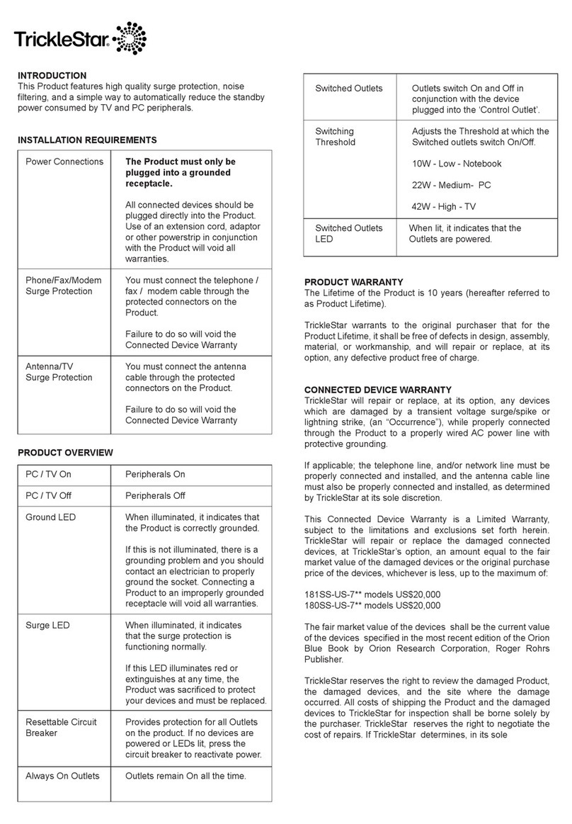
  9. TrickleStar SensorClick TS1802MS User manual

TrickleStar SensorClick TS1802MS User manual

© 2018 TrickleStar Inc.
TrickleStar®is a registered trademark of TrickleStar Inc. All other trademarks are the
property of their respective owners. The information in this document is subject to
change without notice. TrickleStar assumes no responsibility for any errors that may
appear in this document.
REV 2 – 3 May 2018
®
®
For technical support go to
www.tricklestar.com
or call 1-888-700-1098
www.tricklestar.com
PRODUCT INFORMATION
Quick Start Guide
& Instruction Manual
Advanced Powerstrip with
Motion Sensor
Advanced Powerstrip
with Motion Sensor
TS1802MS
SensorClick™ is a modular powerstrip and sensor system that allows you to use
any SensorClick advanced power strip with any SensorClick accessory device.
With an extensive and growing list of power strips and sensors, you can quickly
and inexpensively set up an energy-saving solution to suit any application.
The TS1802MS is a SensorClick 7-outlet Advanced PowerStrip and Motion
Sensor. This solution reduces active and standby power wasted by electronics by
removing the supply of power to the switched outlets if no motion is detected
within the countdown timer period (default: 30 minutes). The two always-on
outlets receive constant power and are not controlled by the motion sensor.
Feature Diagram
8 ft. cord
RJ11 connector
Passive infrared (PIR)
motion sensor
Premium-quality,
FIREPROOF
surge protection
LED indicators
RJ11
sensor port
4 ft. heavy-duty
power cord
Angled Space
Saver Plug
Rear mounting holes
(back)
Switched (energy-saving)
outlets (5)
Child protective outlet
covers
Transformer-spaced
outlet
Always-on outlets (2)
Resettable
circuit breaker
®
always on switched
always on
surge
ground
switched
sensor
RESET
OFF
always on
always on switched
LED indicators
Surge LED: When illuminated green, this LED indicates that the
surge protection is functioning normally. If this LED illuminates red or
extinguishes at any time, the Product was sacrificed to protect your
devices and must be replaced.
Ground LED: When illuminated green, this LED indicates that the
Product is correctly grounded. If not illuminated, there is a grounding
problem, and you must contact an electrician to properly ground the
outlet. Surge protection will not work with an improperly grounded
outlet.
Switched LED: When illuminated green, this LED indicates that the
switched outlets are receiving power.
RJ11 sensor port
Plug the motion sensor into this port. There will be a soft audible
‘click’ when the connector is inserted correctly.
The motion sensor must be plugged into the RJ11 sensor port in
order for the switched outlets to function correctly.
Resettable circuit breaker
The Product provide surge protection for all outlets. If no devices are
powered or the LEDs are not illuminated, press the circuit breaker
switch to “RESET” to reactivate power.
Always-on outlets
The always-on outlets receive continuous power and remain on all of
the time.
Switched outlets
The switched outlets are controlled by the motion sensor and receive
power when motion is detected. If no motion is detected within the
countdown timer period, power supplied to switched outlets is
removed, and plug-in electronics power down. The switched outlets
will remain off if the motion sensor is not connected.
< > outlet
The first switched outlet, marked < > senses current and determines
the state of the device plugged into it. This status is used by the
SensorClick motion sensor to determine if the connected device is on
or off and to provide extra energy saving features.
SensorClick Motion Sensor
The motion sensor is connected to the power strip via the RJ11 port
marked “sensor.” Mount the motion sensor to a clean and dry flat
surface. The motion sensor must be located within line of sight of
motion in order to function properly.
always on switched
Introduction Getting to Know the Product
< tv >
Plug in devices that require
continuous power into the
always-on outlets (e.g.,
modem, CPU).
Plug peripheral electronics
into the outlets on the power
strip labeled “switched”.
Plug the SensorClick motion
sensor into the port on the side
of the power strip that looks
like a phone jack and is
marked “sensor”.
always on
< >
surge
ground
switched
sensor
always on
switched
Step 1
always on
switched
Step 2 Step 3
Mount the motion sensor to a
flat surface (e.g., under the
desk) aiming at the area you
wish to detect movement.
Plug the power strip into a
grounded outlet receptacle. The
ground and surge lights on the
power strip will illuminate
indicating the that power strip is
properly grounded, and that
surge protection is active.
Step 4 Step 5
There is no power supplied to the switched outlets.
The SensorClick motion sensor must be connected to the power strip, and
motion must be detected to turn on the switched outlets.
Alternatively, press the button on the motion sensor to manually turn on the
switched outlets.
!
The SensorClick motion sensor is blinking.
This is a notification that no motion has been detected within the
countdown timer period, and that the electronics plugged into the switched
outlets will soon shut off.
The LED on the motion sensor will also flash each time motion is detected.
!
The electronics plugged into the switched oulets keep switching off.
The power strip shuts off the electronics plugged into the switched outlets
after 10/30/60 minutes if no motion is detected by the motion sensor.
Ensure that the motion sensor is placed in a proper location and can detect
movement. The countdown timer will reset for another 10/30/60 minutes
each time motion is detected.
!
Troubleshooting
There is no power supplied to any of the outlets.
Ensure that the circuit breaker switch on the top of the power strip is not set
to off. If so, flip the switch to reset the circuit breaker.
!
• Twice for 10 minutes
• Three times for 30 minutes
• Four times for 60 minutes
After the countdown timer is set, the LED will flash
the same number of times the button was pressed
to confirm the new timer setting.
To configure the countdown timer, press and hold
the button on the side of the SensorClick motion
sensor for 5 seconds until the red LED illuminates.
Then press:
The SensorClick motion sensor has a configurable countdown timer that has a
default setting of 30 minutes.
Important: The product must only be plugged into a grounded outlet receptacle. All
connected electroncis should be plugged directly into the product. Use of an extension
cord, adaptor, or any power strip in conjunction with the Product will void all warranties.
!
Installation Instructions Programming the Countdown Timer
The Lifetime of the Product is 10 years (hereafter referred to as Product Warranty).
TrickleStar warrants to the original purchaser that for the Product Warranty it shall be
free of defects in design, assembly, material, or workmanship and will repair or
replace, at its option, any defective product free of charge.
TrickleStar will repair or replace, at its option, any devices which are damaged by a
transient voltage surge/spike or lightning strike (an “Occurrence”) while properly
connected through the Product to a properly-wired AC power line with protective
grounding.
If applicable, the telephone line and/or network line must be properly connected and
installed, and the antenna cable line must also be properly connected and installed
as determined by TrickleStar at its sole discretion.
This Connected Device Warranty is a limited warranty, subject to the limitations and
exclusions set forth herein. TrickleStar will spend to repair or replace the damaged
connected equipment, at TrickleStar’s option, an amount equal to the fair market
value of the damaged equipment or the original purchase price of the equipment,
whichever is less, up to the maximum amount of $20,000.
TrickleStar reserves the right to review the damaged Product, the damaged devices,
and the site where the damage occurred. All costs of shipping the Product and the
damaged devices to TrickleStar for inspection shall be borne solely by the purchaser.
TrickleStar reserves the right to negotiate the cost of repairs. If TrickleStar
determines, in its sole discretion, that it is impractical to ship the damaged devices to
TrickleStar, TrickleStar may designate, in its sole discretion, a repair facility to inspect
and estimate the cost to repair such devices. The cost, if any, of shipping the devices
to and from such repair facility shall be borne solely by the purchaser.
Damaged Product and connected devices must remain available for inspection until
the claim is finalized. The site or location of damage must remain unchanged and
available for inspection until inspected by TrickleStar or agents of TrickleStar.
Whenever claims are settled, TrickleStar reserves the right to be subrogated under
any existing insurance policies the claimant may have. All above warranties are null
and void if:
• The Product in use during the occurrence was not provided to TrickleStar for
inspection upon TrickleStar ’s request at the sole expense of the purchaser.
• TrickleStar determines that the Product has not been installed in accordance
with the Installation Requirements, or altered in any way.
• TrickleStar determines that the damage did not result from the Occurrence, or
that no occurrence in fact took place, or that the repair or replacement of the
damaged devices is covered under a manufacturer’s warranty.
• TrickleStar determines that the connected devices were not used under normal
operating conditions or in accordance with any labels or instructions.
• The Product was not plugged directly into a grounded outlet receptacle.
• The Product is “daisy-chained” together in serial fashion with other power strips,
UPS devices, other surge protectors, or extension cords.
• A three-to-two-prong adapter was used.
• The Product was not used indoors.
Product Warranty
Connected Device Warranty
Making a Warranty Claim
Copyright and Disclaimer
This Product is not for use with aquariums and all other water-related products. Use
only indoors and in dry locations. The Connected Device Warranty only protects
against damage to properly-connected devices where TrickleStar has determined, in
its sole discretion, that the damage resulted from an Occurrence, and does not
protect against acts of God (other than lightning) such as flood, earthquake, war,
vandalism, theft, normal-use wear and tear, erosion, depletion, obsolescence, abuse,
damage due to low voltage disturbances (i.e. brownouts or sags), non-authorized
program, or device modification or alteration. This is the sole warranty of TrickleStar;
there are no other warranties, expressed or, except as required by law, implied,
including the implied warranty or condition of quality, merchantability or fitness for a
particular purpose, and such implied warranties, if any, are limited in duration to the
term of this warranty. Some states do not allow limitations on how long an implied
warranty lasts, so the above limitations may not apply to you.
In no event shall TrickleStar be liable for incidental, special, direct, indirect,
consequential or multiple damages such as, but not limited to, lost business or profits
arising out of the sale or use of any Product even if advised of the possibility of such
damages. This warranty gives you specific legal rights, and you may also have other
rights, which may vary from state to state. Some states do not allow the exclusion or
limitation of incidental or consequential damage, so the above limitations may not
apply to you.
This warranty is valid only for the original purchaser of the product. All damage claims
against the product must be made within 30 days from the date of the Occurrence and
must be accompanied by a receipt for the damaged devices, or the warranty is void.
Warranty is valid in the USA and Canada.
Go to www.tricklestar.com, print our warranty claim form, and email it to
warranty@tricklestar.com.
Provide the following information:
• Product part number
• A list of the devices that were connected to the Product at the time of the
occurrence
• A list of the devices that were damaged during the occurrence and the extent of
the damage
• The date of the Occurrence
• When and where you purchased the Product
• A copy of original purchase receipt
A Customer Service Representative will then instruct you on how to forward your
devices, receipt, and product in use during the Occurrence and how to proceed with
your claim.
©2018 TrickleStar Inc. TrickleStar®is a registered trademark of TrickleStar Ltd. Any
typographical, clerical or other error or omission in this document or other documents
or information issued by TrickleStar shall be subject to correction without any liability
on the part of TrickleStar without notice.
Warranty Information
Other TrickleStar Surge Protector manuals

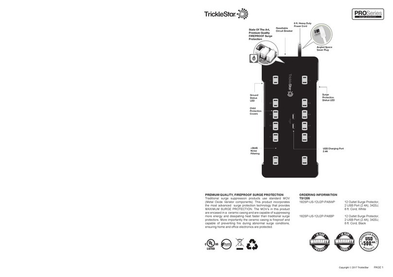
TrickleStar Pro Series User manual

TrickleStar

TrickleStar Pro Series User manual

TrickleStar TS1205 User manual

TrickleStar

TrickleStar TS1205 User manual

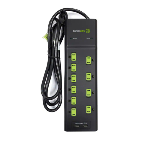
TrickleStar TS1201-7 User manual

TrickleStar

TrickleStar TS1201-7 User manual

Popular Surge Protector manuals by other brands

Belkin BG108000-04 quick start guide

Belkin

Belkin BG108000-04 quick start guide

MTL HICKMAN EdgeBox RI installation guide

MTL

MTL HICKMAN EdgeBox RI installation guide

Panamax MIW-SVIDEO Technical specifications

Panamax

Panamax MIW-SVIDEO Technical specifications

RectorSeal RSH-50 installation instructions

RectorSeal

RectorSeal RSH-50 installation instructions

CPT PSC2 Series installation instructions

CPT

CPT PSC2 Series installation instructions

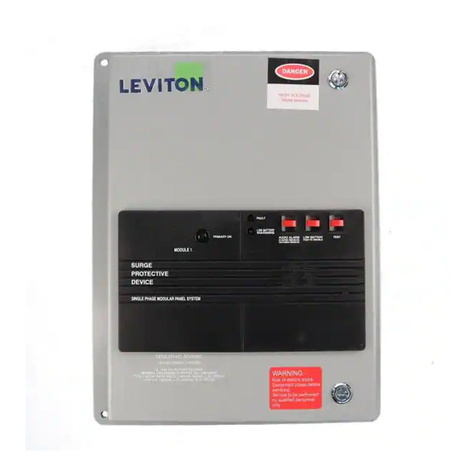
Eaton SPD Series instruction manual

Eaton

Eaton SPD Series instruction manual

Philips SPP3038A/17 user manual

Philips

Philips SPP3038A/17 user manual

PSP VB1-100-4XP Installation notes

PSP

PSP VB1-100-4XP Installation notes

Siemens 5SD7 413-2 Installation instruction

Siemens

Siemens 5SD7 413-2 Installation instruction

Wapeul WyPLUG user manual

Wapeul

Wapeul WyPLUG user manual

Radio Shack 61-2434 owner's manual

Radio Shack

Radio Shack 61-2434 owner's manual

BITS TCG-6MVR user guide

BITS

BITS TCG-6MVR user guide

Panamax M8C-PRO instructions

Panamax

Panamax M8C-PRO instructions

hager WXH20 Series manual

hager

hager WXH20 Series manual

Transtector ALPU-EXLT installation instructions

Transtector

Transtector ALPU-EXLT installation instructions

CyberPower P600WSURC1 user manual

CyberPower

CyberPower P600WSURC1 user manual

Dynex DX-PT413 Limited warranty

Dynex

Dynex DX-PT413 Limited warranty

Cable Innovations DLPS-15D Installation and Information Sheet

Cable Innovations

Cable Innovations DLPS-15D Installation and Information Sheet

manuals.online logo
manuals.online logoBrands
  • About & Mission
  • Contact us
  • Privacy Policy
  • Terms and Conditions

Copyright 2025 Manuals.Online. All Rights Reserved.