ASCO POWER TECHNOLOGIES 360 User manual

Surge Protective Devices Installation & Operation Manual
Model 360

© 2020 ASCO Power Technologies. All Rights Reserved
For access to self-service tools and chat support visit se.com/us/en/work/support or call 1-888-778-2733 for technical assistance
2
IO-70067
01/2020

© 2019 ASCO Power Technologies
All Rights Reserved
Model 360 Surge Protective Device (SPD)
Table of Contents
IO-70067
3
Precautions
Introduction
Unpacking and Preliminary Inspection
Storage
Identication Nameplate
SPD Location Considerations
Environment
Audible Noise
Mounting
Service Clearance
Equipment Performance
Electrical
Voltage Rating
Branch Circuit Overcurrent Protection and Disconnect Means
Location of Surge Protective Device (SPD)
System Grounding
Wiring and Installation
Parts List
Wiring Connection
Specications
Surface Mount Installation
Flush Mount Installation
Operation
LED Status Indicators
Connecting Optional Form C Dry Contact
UL 1283 Required Language concerning the installation of EMI Filters
Preventive Maintenance
5
6
7
7
7
7
7
7
7
7
7
8
8
9
9
10
10
11
11
11
12
13
14
14
15
15
16

© 2020 ASCO Power Technologies. All Rights Reserved
For access to self-service tools and chat support visit se.com/us/en/work/support or call 1-888-778-2733 for technical assistance
4
IO-70067
01/2020
Safety Information
Important Information
Read these instructions carefully and look at the equipment to become
familiar with the device before trying to install, operate, service or maintain it.
The following special messages may appear throughout thisbulletin or on the
equipment to warn of potential hazards or to call attention to information that
clarifies or simplifies a procedure.
The addition of either symbol to a “Danger”or “Warning” safety label
indicates that an electrical hazard exists which will result inpersonal
injury if the instructions are not followed.
This is the safety alert symbol. It is used to alert you to potential
personal injury hazards. Obey all safety messagesthat follow this
symbol to avoid possible injury or death.
DANGER
DANGER indicates a hazardous situation which, if not avoided,
will result in death or serious injury.
WARNING
WARNING indicates a hazardous situation which, if not avoided,
could result in death or serious injury.
CAUTION
CAUTION indicates a hazardous situation which, if not avoided,
could result in minor or moderateinjury.
NOTICE
NOTICE is used to address practices not related to physical injury. The safety
alert symbol shall not be used with this signal word.
Please Note
Electrical equipment should be installed, operated, serviced, and maintained only
by qualified personnel. No responsibility is assumed by ASCO Power Technologies
for any consequences arising out of the use of this material.
A qualified person is one who has skills and knowledge related to the
construction, installation, and operation of electrical equipment andhas received
safety training to recognize and avoid the hazards involved.

© 2020 ASCO Power Technologies. All Rights Reserved
For access to self-service tools and chat support visit se.com/us/en/work/support or call 1-888-778-2733 for technical assistance
5
IO-70067
01/2020
ASCO 360 Surge Protective Device (SPD)
Precautions
Precautions
HAZARD OF ELECTRIC SHOCK, EXPLOSION, OR ARC FLASH
• Apply appropriate personal protective equipment (PPE) and follow safe
electrical work practices. See NFPA 70E, NOM-029-STPS or CSA Z462.
• This equipment must only be installed and serviced by qualied electri-
cal personnel.
• Turn o all power supplying this equipment before working on or inside
equipment.
• Always use a properly rated voltage sensing device to conrm power is o.
• Replace all devices, doors and covers before turning on power to this
equipment.
• This equipment must be eectively grounded per all applicable codes.
Use an equipment-grounding conductor to connect this equipment to the
power system ground.
Failure to follow these instructions will result in death or serious injury.
WARNING: This product can expose you to chemicals including
DINP, which is known to the State of California to cause cancer, and
DIDP which is known to the State of California to cause birth defects
or other reproductive harm. For more information go to: www.
P65Warnings.ca.gov.
NOTICE
LOSS OF BRANCH CIRCUIT POWER / LOSS OF SURGE
SUPPRESSION
• Perform periodic inspection of the surge protective device status
indicator lights as part of the preventative maintenance schedule.
• Promptly replace the surge protective device when an alarm state
exists.
• Use dry contacts to signal an alarm state to the central supervisory
system for unmanned, inaccessible, or critical installations.
• Use multiple surge protective devices to achieve redundancy for critical
applications.
Failure to follow these instructions can result in equipment damage.
At end-of-life conditions, Surge Protective Devices (SPDs) can lose their
ability to suppress power system transient voltage spikes and attempt to
draw excessive current from the line. This SPD is equipped with overcurrent
and overtemperature components that will automatically disconnect the
surge suppression elements from the mains should the surge suppression
elements reach end of life. Tripping of the branch circuit breaker or fuse
feeding the SPD can occur. Mitigate the tripping of the branch circuit breaker
or fuse feeding the SPD by coordinating the surge suppression elements
with the branch circuits.
DANGER

© 2020 ASCO Power Technologies. All Rights Reserved
For access to self-service tools and chat support visit se.com/us/en/work/support or call 1-888-778-2733 for technical assistance
6
IO-70067
01/2020
ASCO 360 Surge Protective Device (SPD)
Introduction
HAZARD OF ELECTRIC SHOCK, EXPLOSION, OR ARC FLASH
• Do not energize the surge protective device until the electrical system is
completely installed, inspected and tested.
• Ensure all conductors are connected and functional.
• Verify the voltage rating of the device and system prior to energizing.
• Perform high-potential insulation testing, or any other tests where surge
protective device components will be subjected to voltages higher than
their rated turn-on voltage, with the neutral and surge protective device
disconnected from the power source
Failure to follow these instructions will result in death or serious injury.
HAZARD OF ELECTRIC SHOCK, EXPLOSION, OR ARC FLASH
• Apply appropriate personal protective equipment (PPE) and follow safe
electrical work practices. See NFPA 70E, NOM-029-STPS or CSA Z462.
• This equipment must only be installed and serviced by qualied
electrical personnel.
• Turn o all power supplying this equipment before working on or inside
equipment.
• Always use a properly rated voltage sensing device to conrm power is
o.
• Replace all devices, doors and covers before turning on power to this
equipment.
• This equipment must be eectively grounded per all applicable codes.
Use an equipment-grounding conductor to connect this equipment to the
power system ground.
Failure to follow these instructions will result in death or serious injury.
Proper installation is imperative to maximize the ASCO 360 SPDs eective-
ness and performance. Follow the steps outlined in this instruction bulletin
to ensure proper installation. Read the entire instruction bulletin before
beginning the installation. These instructions are not intended to replace
national or local electrical codes. Check all applicable electrical codes to
verify compliance. Installation of ASCO 360 surge suppressors must only be
performed by qualied electrical personnel.
DANGER
DANGER
Introduction
Note: For access to self-service
tools and chat support visit
se.com/us/en/work/support or
call 1-888-778-2733 for technical
assistance

© 2020 ASCO Power Technologies. All Rights Reserved
For access to self-service tools and chat support visit se.com/us/en/work/support or call 1-888-778-2733 for technical assistance
7
IO-70067
01/2020
ASCO 360 Surge Protective Device (SPD)
Unpacking and Preliminary Inspection
Unpacking and Preliminary
Inspection
Storage
Identication Nameplate
SPD Location
Considerations
Environment
Mounting
Service Clearance
Equipment Performance
Inspect the entire shipping container for damage or signs of mishandling be-
fore unpacking the device. Remove the packing material and further inspect
the device for any obvious shipping damage. If any damage is found and is
a result of shipping or handling, immediately le a claim with the shipping
company.
The device should be stored in a clean, dry environment. Storage tempera-
ture is -40 °F to +185 °F (-40°C to +85°C). All of the packaging materials
should be left intact until the device is ready for installation.
The identication nameplate is located on the side of the unit.
The device is designed to operate in an ambient temperature range of
-40 °F to +185 °F (-40°C to +85°C) with a relative humidity of 0 to 95%
non-condensing. This device has a Type 4X housing.
The device background noise is negligible and does not restrict the location
of the installation.
The device has been designed to be surface mounted. An additional ush
mount kit is also available if required (KITFMXF).
The service clearance should meet all applicable code requirements.
To obtain optimum surge suppression, locate the SPD as close as possible
to the circuitry being surge-limited to minimize the wire length. Minimizing
the wire length reduces the impedance between the circuitry and the SPD.
Refer to the Voltage Protection Rating (VPR) values on the SPD nameplate.
These VPR values were obtained by testing the SPD with six-inch long
leads (per UL1449). For every additional foot of wire beyond six inches, the
eective VPR increases by approximately 160 volts.
ASCO POWER TECHNOLOGIES, LP
CAT# 360_____________
PART# __XMS_________
VOLTAGE: ____________V 50-60Hz
MAX RATED AMBIENT AIR TEMP: ________
MFG DATE: _________
Suitable for use on a circuit capable of delivering not more
than _________ rms symmetrical amperes
ENC TYPE: XXXX
In: 20 kA
____V
VOLTAGE
PROTECTION RATING
CW
UL 1449-4
SPD TYPE __
MCOV: ____ / _____
L-N
L-G
N-G
L-L
____
____
____
____
UL
Holigram
Audible Noise

© 2020 ASCO Power Technologies. All Rights Reserved
For access to self-service tools and chat support visit se.com/us/en/work/support or call 1-888-778-2733 for technical assistance
8
IO-70067
01/2020
ASCO 360 Surge Protective Device (SPD)
Electrical
HAZARD OF ELECTRIC SHOCK, EXPLOSION, OR ARC FLASH
Conrm the surge protective device voltage rating on the module or
nameplate label is not less than the operating voltage.
Failure to follow these instructions will result in death or serious injury.
Prior to mounting the SPD, verify that the device has the same voltage
rating as the power distribution system in which it is installed. Compare the
nameplate voltage or model number on the SPD with the nameplate of the
electrical distribution equipment.
The specier or user of the device should be familiar with the conguration
and arrangement of the power distribution system in which the SPD is to be
installed. The system conguration of any power distribution system is based
strictly on how the secondary windings of the transformer supplying the ser-
vice entrance main or load are congured. This includes whether or not the
transformer windings are referenced to earth via a grounding conductor. The
system conguration is not based on how any specic load or equipment
is connected to a particular power distribution system. See Table 1 for the
service voltage of each SPD.
Electrical
Voltage Rating
Table 1: Model 360 Service Voltages
Figure 1: Split Phase Conguration Figure 2: Single Phase Conguration
DANGER
Phase A (BLK)
Phase B (BLK)
Neutral (WHT)
Ground (GRN)
BLK
BLK
WHT
Phase A (BLK)
Neutral (WHT)
Ground (GRN)
BLK
WHT
GRN
GRN
Phase A (BLK)
Phase B (BLK)
Neutral (WHT)
Ground (GRN)
BLK
BLK
WHT
Phase A (BLK)
Neutral (WHT)
Ground (GRN)
BLK
WHT
GRN
GRN
Voltage Codes
P A W J 2
Per Phase
kA Rating
System
Modes of
Protection
(Default)
Connec-
tion Type
Monitoring
Options
Enclosure UL 1449
Type
Accessory/
Option(s)
kA Rating
Per Phase
360
Model 360
Product Line
J = NEMA 4X non-metallic
(Polycarbonate)
Size - 8.3 x 3.6 x 3.0 in.
(210.8 x 91.4 x 76.2 mm)
W = Wire leads
S =
LEDs
R =
LEDs / relay
2 = UL 1449 type 2
0 = No trailing accessory/option
X = Yes trailing accessory/option
XADDF1 = EMI/RFI filtering
Common Systems
120S = 240/120V Split Phase - 1Ø,
3W + ground (Fig 1)
120N = 120V Single Phase (Fig 2)
18 = 180kA
14 = 144kA
10 = 108kA
07 = 72kA
03 = 36kA
Available Accessories
(Order Seperatly)
XMFMKIT - Flush Mount Kit

© 2020 ASCO Power Technologies. All Rights Reserved
For access to self-service tools and chat support visit se.com/us/en/work/support or call 1-888-778-2733 for technical assistance
9
IO-70067
01/2020
ASCO 360 Surge Protective Device (SPD)
Electrical
Branch Circuit Overcurrent
Protection and Disconnect Means
Location of Surge Protective
Device (SPD)
HAZARD OF ELECTRIC SHOCK, EXPLOSION, OR ARC FLASH
• Use conductors rated for the Overcurrent Protection Device (OCPD) per
applicable codes.
• Use conductors rated for the application per applicable codes.
Failure to follow these instructions will result in death or serious injury.
A branch circuit Overcurrent Protection Device (OCPD) either in the form of
a circuit breaker or fuse must be provided for the ASCO 360 Type 2 device.
The branch circuit OCPD should either provide or include a disconnecting
means.
Since the current drawn by the ASCO 360 device during normal operation is
negligible, the ASCO 360 device can be connected to a dedicated, separate
branch circuit or connected to a suitable existing branch circuit.
When connected to a separate, dedicated branch circuit, the OCPD setting
must be selected to protect the conductors feeding the ASCO 360 device
per applicable state and local building codes.
UL 1449 Type 1 SPDs have been designed and approved for line side appli-
cations prior to the main service disconnect without supplemental overcur-
rent protection. Type 2 SPDs must be installed on the load side of the main
Overcurrent Protective Device (OCPD). All installations should either provide
or include a disconnecting means.
Locate the SPD as close as possible to the circuit mains being surge-limited
to minimize the wire length and optimize SPD performance. Avoid long wire
runs so that the device will perform as intended. To reduce the impedance
that the wire displays to surge currents, the phase, neutral, and ground
conductors (wye and high-leg delta congurations), or phase and ground
conductors (delta congurations), must be routed within the same conduit
and tightly bundled or twisted together to optimize device performance.
Avoid sharp bends in the conductors. See Figures 2 and 3.
DANGER

© 2020 ASCO Power Technologies. All Rights Reserved
For access to self-service tools and chat support visit se.com/us/en/work/support or call 1-888-778-2733 for technical assistance
10
IO-70067
01/2020
ASCO 360 Surge Protective Device (SPD)
System Grounding
NOTICE
LOSS OF SURGE SUPPRESSION
• Verify that the service entrance equipment is bonded to ground in
accordance with all applicable codes.
Failure to follow these instructions can result in equipment damage.
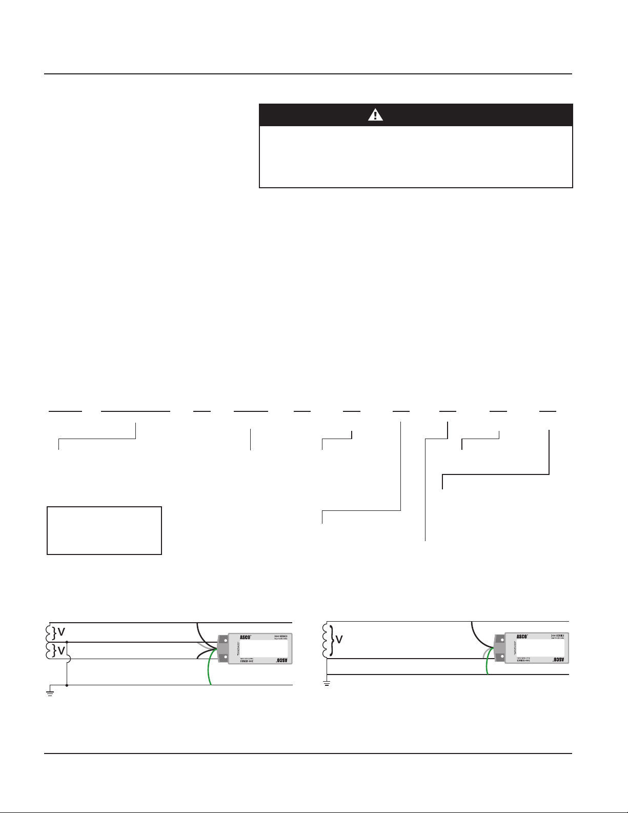
The ASCO 360 has SPD elements connected from phase to ground. It is
critical that there be a robust and eective connection to the building
grounding structure. The grounding connection must utilize an equipment
grounding conductor run with the phase and neutral connection of the power
system. Do not connect the SPD to a separate isolated ground.
For proper voltage suppression by the ASCO 360 SPD, use a single-point
ground system where the service entrance grounding electrode system is
connected to, and bonded to, all other available electrodes, building steel,
metal water pipes, driven rods, etc. (for reference, see NEC Art 250). The
ground impedance measurement of the electrical system must be as low as
possible and in compliance with all applicable codes for sensitive electronic
and computer systems.
System Grounding
Wiring and Installation
NOTICE
LOSS OF SURGE SUPPRESSION
• Install an insulated grounding conductor inside a metallic raceway when
the raceway is used as an additional grounding conductor. Size the
conductor in accordance with all applicable codes.
• Maintain adequate electrical continuity at all raceway connections.
• Do not use isolating bushings to interrupt a metallic raceway run.
• Do not use a separate isolated ground for the surge protective device.
• Verify proper equipment connections to the grounding system.
• Verify ground grid continuity by inspections and testing as part of a
comprehensive electrical maintenance program.
Failure to follow these instructions can result in equipment damage.
HAZARD OF ELECTRIC SHOCK, EXPLOSION, OR ARC FLASH
• Apply appropriate personal protective equipment (PPE) and follow safe
electrical work practices. See NFPA 70E, NOM-029-STPS or CSA Z462.
• This equipment must only be installed and serviced by qualied electri-
cal personnel.
• Turn o all power supplying this equipment before working on or inside
equipment.
• Always use a properly rated voltage sensing device to conrm power is
o.
• Replace all devices, doors and covers before turning on power to this
equipment.
• This equipment must be eectively grounded per all applicable codes.
Use an equipment-grounding conductor to connect this equipment to the
power system ground.
• Conrm the surge protective device voltage rating on the module or
nameplate label is not less than the operating voltage.
Failure to follow these instructions will result in death or serious injury.
DANGER

© 2020 ASCO Power Technologies. All Rights Reserved
For access to self-service tools and chat support visit se.com/us/en/work/support or call 1-888-778-2733 for technical assistance
11
IO-70067
01/2020
Items included in the package consis of the following:
• 1 Model 360 Surge Protective Device
• Data Sheet
• User’s Manual (this document)
If the Flush Mount Kit (Part #XMFMKIT) was ordered, additional parts are
supplied as follows:
• 1 Flush Mount Plate
• 4 Pan-head Screws
ASCO 360 Surge Protective Device (SPD)
Wiring
Parts List
Follow steps 1 through 6 to make wiring connections:
1. Turn o all power supplying this equipment before working on or inside
any enclosure containing this equipment.
2. Conrm SPD is rated for your system by comparing voltage measure-
ments to the Line Voltage (L-N) on the product label.
3. Identify proper location for the SPD. Locate as close as possible to
the mains of the panel being surge-limited so the wires are as short as
possible. Mount unit securely.
Note: The SPD must be installed in an accessible location (not within
walls unless surface mounted with the ASCO KITFMXF ush mount kit).
4. Install in accordance with national and local electrical codes and match
the branch circuit Overcurrent Protection Device (OCPD) to the wire
size.
5. Twist conductors 1/2 turn or more for every twelve inches of length.
6. Do not loop or coil wires. Be sure to maintain adequate wire bending
space per NEC.
Specications
Wiring Connections
Voltage Rating 120/240V Split Phase - 1Ø, 3W+Grnd
120 V Single Phase - 1ø, 2W + Gnd
Audible Noise None
Service Clearance 36 in (94.1 cm) in front of the unit
Installation Type Chase Nipple
Wire Length vs.
Response Time and
Let-Through Voltage
1 ft (31.7 cm) of wire = 1 nanosecond. 160
volts per foot (6kV,3kA, 8/20 microseconds) are
added to the clamp voltage.
Wire Size & Installation
Torque Wire Size = #10 AWG, torque to 18 in-lbs.
Circuit Breaker
Connection 30 Amp
System Grounding
Per IEEE STD 142-1991. For sensitive
electronics/computer systems, the
recommended ground impedance is 25 ohms or
less.

© 2020 ASCO Power Technologies. All Rights Reserved
For access to self-service tools and chat support visit se.com/us/en/work/support or call 1-888-778-2733 for technical assistance
12
IO-70067
01/2020
L1 L2
GN
BREAKER
ASCO 360 Surge Protective Device (SPD)
Wiring
Note: Mount the unit as close as possible to the protected panel.
1. Identify breaker location and SPD location. See gure 2 below.
2. Conrm SPD is rated for your system by comparing voltage measure-
ments to the Line Voltage (L1 – L2 for split phase or L-N for single
phase). L1-L2 should be 240 Vac and L-N will be 120 Vac.
3. Turn o all power supplying this equipment before working on or inside
any enclosure containing this equipment.
4. Determine mounting location. See gure 2 below.
5. Remove an appropriately sized knockout from the panel.
6. Mount SPD. Weather resistant applications require additional sealing,
etc. See gure below.
7. Install in accordance with national and local electrical codes and match
the branch circuit Overcurrent Protection Device (OCPD) to the wire
size. Recommended breaker size is 30 A and wire size 10 AWG.
8. Do not loop wires. Trim excessive wire length.
Figure 2: Typical panel Installation
Surface Mount Installation
▪Use closest
breaker to SPD
▪Locate SPD close to
intended breaker
▪Keep Leads Short as
Possible
▪Avoid Sharp Bends
▪Rotate Model
360 such that
LED indicators
are most visible
▪Outdoor installation requires
appropriate weather sealing
at nipple (gasket, sealing
conduit, etc.)
Loads
HAZARD OF ELECTRIC SHOCK, EXPLOSION, OR ARC FLASH
• For outdoor installation use an appropriate weather sealing at the nipple
(o-ring, sealing conduit, etc.)
Failure to follow these instructions will result in death or serious injury.
DANGER

© 2020 ASCO Power Technologies. All Rights Reserved
For access to self-service tools and chat support visit se.com/us/en/work/support or call 1-888-778-2733 for technical assistance
13
IO-70067
01/2020
ASCO 360 Surge Protective Device (SPD)
Wiring
1. Select the location where the SPD and Flush Mount Kit (XMFMKIT) will
be mounted. Aesthetics may have to be sacriced in order to achieve
maximum surge protection.
2. Place the Flush Mount Kit plate where it will be mounted and trace the
center hole and mounting holes. Cut this shape into the mounting sur-
face and mount the XMFMKIT panel to the mounting surface.
3. BE CAREFUL TO NOT DROP THE SPD INTO THE WALL.
4. Install the SPD to the back side of the Flush Mount Kit plate using the
four 8/32 x 5/8 in. Thread Cutting Screws provided with the XMFMKIT kit.
5. Proceed with #6 on page 12.
Flush Mount Installation
Instructions
Insert ushmount screw through
hole in each corner or punch a
small starting hole in center of each
translucent window (located in all 4
corners of the label).
Figure 3: Typical Model 360 SPD installation (Dimensions - in./mm.)

© 2020 ASCO Power Technologies. All Rights Reserved
For access to self-service tools and chat support visit se.com/us/en/work/support or call 1-888-778-2733 for technical assistance
14
IO-70067
01/2020
ASCO 360 Surge Protective Device (SPD)
Operation
Operation
HAZARD OF ELECTRIC SHOCK, EXPLOSION, OR ARC FLASH
• Apply appropriate personal protective equipment (PPE) and follow safe
electrical work practices. See NFPA 70E, NOM-029-STPS or CSA Z462.
• This equipment must only be installed and serviced by qualied
electrical personnel.
• Turn o all power supplying this equipment before working on or inside
equipment.
• Always use a properly rated voltage sensing device to conrm power is
o.
• Replace all devices, doors and covers before turning on power to this
equipment.
• This equipment must be eectively grounded per all applicable codes.
Use an equipment-grounding conductor to connect this equipment to the
power system ground.
Failure to follow these instructions will result in death or serious injury.
DANGER
LED Status Indicators Diagnostic LEDs are located on the front of the ASCO 360 SPD device.
They operate as follows:
• Verify that all phase voltages are present. If any of the LEDs are not
illuminated, the device may not be installed correctly. Check the power
supply and service voltage. Upon energizing the SPD, check the LED status.
• If all of the LEDs are illuminated, surge suppression is operating.
• If one or more LEDs are not illuminated, there is a loss of surge
suppression on that phase.
• If an inoperative condition occurs the device must be replaced by qualied
electrical personnel.
Light 1 Light 2 Corrective Action
Out Out Check Power Supply
Before Replacing Unit
Green Green No action
Out Green Replace Unit
Green Out Replace Unit
Note: Single phase units will only have one light, 2 light conguration is for
split phase units only.

© 2020 ASCO Power Technologies. All Rights Reserved
For access to self-service tools and chat support visit se.com/us/en/work/support or call 1-888-778-2733 for technical assistance
15
IO-70067
01/2020
ASCO 360 Surge Protective Device (SPD)
Preventive Maintenance
UL 1283 Required Language
concerning the installation
of EMI Filters
Connecting Optional Form C
Dry Contact
a. An insulated grounding conductor that is identical in size and insulation
material and thickness to the grounded and ungrounded circuit supply
conductors except that it is green with or without one of more yellow
stripes, is to be installed as part of the circuit that supplies the lter.
Reference NEC Table 250-122 for the appropriate size of the grounding
conductor
b. The grounding conductor mentioned in item a is to be grounded at the
service equipment or other acceptable building ground such as the
building frame in the case of a high-rise steel frame structure.
c. Any attachment-plug receptacles in the vicinity of the lter are to be
of a grounding type, and the grounding conductors serving these
receptacles are to be connected to ground at the service equipment or
other acceptable building ground such as the building frame in the case
of a high-rise steel-frame structure.
d. Pressure terminal or pressure splicing connectors and soldering lugs
used in the installation of the lter shall be identied as being suitable
for the material of the conductors. Conductors of dissimilar metals shall
not be intermixed in a terminal or splicing connector where physical
contact occurs between dissimilar conductors unless the device is
identied for the purpose and conditions of use.
Three 3 ft. (~1 m) 18 AWG wires are included through the nipple with this
option. See gure below. Gray is Common, Blue is Normally Open and Red
is Normally Closed when energized in its expected installation. (When not
energized, the SPD is no longer in its ‘Normal’ state and contacts will be
reversed.)
Dry contact
leads
(18 AWG)
Power leads
(10 AWG)
Blue Gray
Red
Form C dry contact: Three (3) #18 wires exit the hub
- Gray is common
- Blue is normally closed
- Red is normally open
• For normally closed: Use gray and blue
• For normally open: Use Gray and Red

IO-70067 RevF 01-20
While every precaution has been taken to ensure accuracy and
completeness in this literature, Schneider Electric assumes no
responsibility, and disclaims all liability for damages resulting from
use of this information or for any errors or omissions.
14550 58th Street North
Clearwater, Florida 33760
se.com/us/en/work/support
1-888-778-2733
Preventive Maintenance
HAZARD OF ELECTRIC SHOCK, EXPLOSION, OR ARC FLASH
• Apply appropriate personal protective equipment (PPE) and follow safe
electrical work practices. See NFPA 70E, NOM-029-STPS or CSA Z462.
• This equipment must only be installed and serviced by qualied electri-
cal personnel.
• Turn o all power supplying this equipment before working on or inside
equipment.
• Always use a properly rated voltage sensing device to conrm power is
o.
• Replace all devices, doors and covers before turning on power to this
equipment.
• This equipment must be eectively grounded per all applicable codes.
Use an equipment-grounding conductor to connect this equipment to the
power system ground.
Failure to follow these instructions will result in death or serious injury.
DANGER
Inspect the SPD periodically to maintain system performance and continued
transient voltage surge suppression. During this inspection, check the state
of the display LED status indicators.
Table of contents
Other ASCO POWER TECHNOLOGIES Surge Protector manuals
Popular Surge Protector manuals by other brands

Energenie
Energenie EG-PMS2-WLAN user manual

Wychwood Audionics
Wychwood Audionics F3lite user manual

environmental potentials
environmental potentials EP-2050 Series Installation and maintenance manual

Infinite
Infinite TRANSTECTOR ALPU-TSU installation instructions

M-system
M-system 6SN instruction manual

M-system
M-system MD7PA instruction manual

Nexxt Solutions
Nexxt Solutions Smart Wi-Fi dual plug manual

OBO Bettermann
OBO Bettermann V50-0-280 installation instructions

OBO Bettermann
OBO Bettermann CombiController V50-280 Series installation instructions

Intermatic
Intermatic IG3240RC3 installation instructions

Panamax
Panamax M8-HT instructions

QVS
QVS PP136M Specification sheet