Trico Streamliner DC 30 User manual

1
1
1
1
1
1
User Manual
Technical Information
Mode d’emploi
Informations techniques
Manual del usuario
Información técnica
EN
FR
ES

2
EN English 3–9
FR Français 11–17
ES Español 19–25

3
EN
Product Specification
Product automatic long-term grease and oil dispenser
Power generation hydrogen gas producing drycells
Working pressure max. 5 bar
Adjustment stepless 1–12 months (for standard conditions)
Dispensing rate see table on page 4-6
Operating
temperature
–20°C to +55°C (–4°F to +131°F) ambient temperature
(Note: grease consistency changes with temperature)
Operation/Usage Grease dispenser can be installed in any position, even under
water. Attention: do not expose to direct heat.
Certifications/
Approvals
II 1G Ex ia IIC T6
II 1D Ex iaD 20T 80°C
I M1 Ex ia I
Ingress protection IP68 (dustproof and waterproof)
Usage period within 2 years of production date
Stock temperature recommended at 20°C ± 5°C (65°F ± 5°F)
30 ml 60 ml 125 ml
Weight full ~ 82 g ~ 115g ~ 190 g
Weight empty ~ 55 g ~ 60 g ~ 75 g
R 1/4“
Ø52 mm (2.05 in.)
43 mm (1.7 in.)
Streamliner DC
30
R 1/4“
Ø52 mm (2.05 in.)
14
mm
(0.55 in.)
62 mm (2.4 in.)
Streamliner DC
60
R 1/4“
100 mm (3.9 in.)
Streamliner DC
125
Streamliner DC
30 Ø52 mm (2.05 in.)
Streamliner DC
60
R 1/4“
Ø52 mm (2.05 in.)
14
mm
(0.55 in.)
Streamliner DC
125
14
mm
(0.55 in.)

4
Assembly and Installation
1) Open the lubricator outlet by cutting off seal or removing plug.
Do not remove plug from oil filled units! Cut off the
protruding nipple with a knife; a small black point becomes
visible (opening now guaranteed).
2) To start the Streamliner DC lubricator, set the gas generator to
the required dispensing time (stepless in months, 1–12) using a
3 mm Allen key. The lubricator is activated once the dispensing
time has been set. Take the required dispensing quantity from
the tables on page 5.
3) Note the starting date on the label using a waterproof pen.
4) Clear grease lines and fill them with the appropriate grease.
Screw Streamliner DC onto the greasing point. Apply safety
rules.
5) Once the set dispensing time has expired, replace empty lubri-
cator with the same type or refill. Before restarting, clear grease
lines and fill them with the appropriate grease.
6) The gas generator is sufficient to empty the unit once,
irrespective of the dispensing time set.
Security note: If the lubricator is started without opening the outlet or in case of
blocked grease lines within the installation, the pressure in the lubricator can build up
approx. 5 bar. At an overpressure of approx. 6 bar the lubricator breaks at the defined
breaking point between housing and bottom. The pressure behind the piston releases
and oil or grease can come out at the breaking point.
The correct functioning of the lubricator can only be assured if recommended lubricants
(see table on page 8) and original Streamliner accessories are used, and if the instal-
lation, operating and maintenance instructions are closely followed. The manufacturer
cannot accept any responsibility for damages as a result of ignoring the instructions
mentioned above. Important: Before putting Streamliner DC into operation fill exten-
sions and the lubrication lines with the appropriate Streamliner DC greases using a
grease gun. Use only original accessories.
Temperature/Output rate
The output rate can be adjusted as required, depending on the ambient temperature
(see table).
Example: You want to set the dispensing time for a 125 ml Streamliner DC for 180
days.
Ambient temperature: 20°C Ambient temperature: 55°C
Setting: 6 Setting: 7

5
EN
Streamliner DC 60
Dispensing
time (days) 30 90 180 270 360
ml/day 2.00 0.67 0.33 0.22 0.17
Temperature Setting Setting Setting Setting Setting
–20°C + 2 4 6.5 8
4°C + 2.5 5.5 9 10.5
20°C 136912
40°C 1 3 6.5 9.5 –
55°C 1 3.5 7 10.5 –
+ use larger dispenser with longer dispensing time
– smallest possible output rate reached
Streamliner DC 30
Dispensing
time (days) 30 90 180 270 360
ml/day 1.00 0.33 0.17 0.11 0.08
Temperature Setting Setting Setting Setting Setting
–20°C + 2 3.5 5.5 7.5
4°C + 2.5 5 7.5 10.5
20°C 136912
40°C 1 3 6.5 9.5 –
55°C 1 3.5 7 10.5 –
+ use larger dispenser with longer dispensing time
– smallest possible output rate reached
Streamliner DC 125
Dispensing
time (days) 30 90 180 270 360
ml/day 4.17 1.39 0.69 0.46 0.35
Temperature Setting Setting Setting Setting Setting
–20°C + 2 4 6.5 8.5
4°C + 2.5 5.5 8 10.5
20°C 136912
40°C 1 3 6.5 9.5 –
55°C 1 3.5 7 10 –
+ use larger dispenser with longer dispensing time
– smallest possible output rate reached

6
The values relate to laboratory conditions, with no counterpressure. At low temperatures
in particular, the values may vary between one grease type and another. The dispen-
sers must be replaced once the dispensing time set has expired, even if they are not
completely empty.
The grease quantity dispensed – counter pressure/resistance from
per day is influenced by: the grease lines
– ambient temperature
– viscosity of the grease
Start-up time:
The lubricator requires a certain start-up time until the lubricant is first dispensed.
The start-up time varies in line with the volume dispensed, dispenser size and operating
temperature selected. At 20°C ambient temperature and a dispensing time setting of
12 months, the dispenser outputs the lubricant within one week. The start-up time dou-
bles at low temperatures (–20°C) or with small dispensers (30 ml).
You can reduce the start-up time in such a case by setting a dispensing time on the
lubricator of one month for one to two days and then changing to the desired dispens-
ing time.
Calculation pro:
An online calculation program is available at www.simatec.com (CPalculation pro). This
tool calculates the right setting for the Streamliner DC lubricator if you enter the precise
operating parameters.
Notes:
In order for the unit to function reliably, it is important to have clear, filled grease lines.
It must be ensured that the grease lines are not blocked. Consequently, the grease lines
should always be cleared with a grease gun before starting.
The Streamliner DC can be re-adjusted or switched off during operation.
The values on the gas generator relate to laboratory conditions (see page 4). Depend-
ing on the temperature and setting, it may take several hours (or several days in the
case of long-term settings) until the lubricant is first dispensed.
The user must check the operation of the Streamliner DC regularly.
Grease lines should be no longer than 0.5 m. Recommended bore diameter: 6–8 mm
Resistance in grease lines has to be minimized, narrow passages and right angles
should be avoided.
Use a mounting support in the event of strong vibrations or high accelerations.
The Streamliner DC may only be used to supply a single grease point. No branches
may be made.
Once the lubricator is installed and activated, it must not be removed and mounted
onto another lubrication point.

7
EN
Filling and Refilling (for small quantities)
1a. 2a.
3a. 4.
5. 6.
1b. 2b.
3b.
1.
2.
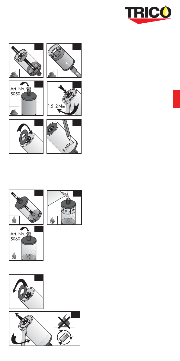
Filling with grease
1a. Push piston all the way forward by blowing
gently with compressed air or with the aid
of a plastic rod (7 mm diameter), towards
the bottom or opening.
2a. Screw on refill nipple (article no. 3012)
and connect grease gun, or screw
connector nipple (3013 or 3014) onto
grease gun. Keep the dispenser pressed
to the adapter during the filling process
so that you do not have to screw on the
refill nipple again. Press grease into the
dispenser. Avoid air bubbles when filling
the unit. Continue the filling process until
the piston has been pushed all the way
back. Do not overfill!
Caution: Lever
presses can create pressure of up to
80 bar, which is enough to destroy
the dispenser.
3a.
Use closing nipple (green) if the dispenser
is to be stored.
4. Position gas generator (make sure the O-ring is positioned correctly)
and attach firmly with a 1.5–2.0 Nm torque key.
5. Clip in cover disk.
6. Note grease type and filling date on the label.
Filling with oil
1b. Push the piston all the way back
(towards the gas generator).
2b. Pour in oil through the opening
at the bottom.
3b. Position non-return valve
(yellow, article no. 5060).
4–6 Continue as above.
Refilling with grease or oil
1. Remove cover disk.
2. Unscrew gas generator (SW 21) and
recycle with other batteries. Never remove
near an open flame! Then continue as
above for filling with grease or oil.
Note
To ensure that the Streamliner DC lubricator
operates reliably, only greases that have
been tested and approved for use with the
Streamliner should be used. In particular, it is
important to ensure the good stability of the
grease against bleeding of the base oil and
a low consistency class (max. NLGI 2). No gua-
rantee claims will be accepted when dispensers
are filled by the user or not explicitly appro-
ved lubricants are used. If in doubt, please
contact our Technical Department or your local
distributor.

8
Lubricants
The standard lubricant range suitable for Streamliner DC includes modern high quality
lubricants tested and modified for the special requirements of grease and oil dispensers.
Datasheets are available online for all lubricants (www.tricocorp.com). Please refer to
these datasheets for the instructions/safety regulations of the grease/oil manufacturers.
Streamliner DC can also be delivered filled with other lubricants or as an empty unit.
Ask for advice.
The operation of Streamliner DC with oils of different viscosities is also
Troubleshooting
Fault Possible cause Remedy
– no grease output – seal not cut off/closing nipple
still in place
– not switched on
– grease lines blocked
– gas generator loose
– open/remove
– switch on
– clear lines with grease gun
– tighten with 2 Nm
– insufficient output – dispensing time too long
– ambient temperature too low
– grease lines blocked/too
narrow
– short-term extreme low
temperatures, piston moves
backwards
– high counter pressure
– set to lower number
– correct setting according to
table, page 16
– clean, allow for free flow of
grease
– none
– clear grease lines, check
installation
– excessive output – dispensing time too short – set to higher number
For other malfunctions contact Trico Corp at 262.261.9336.
The information provided reflects the manufacturer’s current level of development and
understanding. Subject to change. The products are subject to strict manufacturing con-
trols and meet internal works specifications. As a result of the wide range of conditions
and areas of application possible in each case, no guarantee can be provided for effec-
tiveness or success in each individual instance. No responsibility is accepted for damage
or malfunctions caused by incorrect use or improper work on or with the lubricator.
Grease Type NLGI Thickener Type
Mobilith XHP 222 2Lithium Complex
Exxon Unirex EP 2 2Lithium Complex
Mobilith SHC 100 2Lithium Complex
Mobil FM 222 2Aluminum Complex
Mobilith SHC 220 2Lithium Complex
Mobilith SHC PM 460 1.5 Lithium Complex
Mobil Polyrex EM 2Polyurea

9
Recycling Instructions
1) Unscrew gas generator and dispose of
complete unit for battery recycling
(see above). Note: Do not detach lubrica-
tor near an open flame.
2) Dispose of empty housing for PET recyc-
ling. If the lubricator still contains lubricant
after use, please dispose of it in accord-
ance with local regulations.
EU Declaration of Conformity
simatec ag
Stadthof 2 in CH-3380 Wangen a. Aare
declares that the
single point lubricators
simalube & simalube multipoint
are designed and manufactured in
accordance with
Directive 94/9/EC of the European
Parliament and the Council for equipment
and protective systems intended for use in
potentially explosive atmospheres.
The following standards have been applied:
EN 60079-0:2006
EN 60079-11:2007
EN 60079-26:2004
EN 61241-0:2006
EN 61241-11:2006
EN 50303:2000
Notified Body:
TÜV Product Service GmbH
D-80339 Munich
KEMA Quality B.V., NL-6812 AR Arnhem
Certificate No.
KEMA 09ATEX0098
Wangen a. Aare, 20.09.10
Mischa Wyssmann, Managing Director CEO
Trico Corp
262.691.9336
www.tricocorp.com
Streamliner DC has been safety inspected and approved by the following institutions:
• Physikalisch Technische Bundesanstalt, Brunswick, Germany, Nr. 3.42-16990/94
• FM Approvals, USA, Project Identification Number: 3013825
• Technischer Überwachungsverein (TÜV) Rheinland, Cologne, Germany, 12.05.95
• DMT Gesellschaft für Forschung und Prüfung GmbH, Germany Nr. 16420/344/96
• LOBA NRW, Dortmund, Germany, Nr. 12.22.63-4-2
• INERIS, France, Nr. 96.Y.300 X, CROSS ia I
• EECS / BASEEFA, United Kingdom, No. 95 (A) 0692, 1997-04-10
• TÜV Product Service GmbH, Germany, Nr. Z1 08 02 29499 015
• TÜV Product Service GmbH, Germany, Nr. EX3 10 04 29499 016
• KEMA Quality B.V., Netherland Nr. KEMA 09ATEX0098
II 1 G Ex ia IIC T6
• II 1 D Ex iaD 20 T 80°C
I M1 Ex ia I

10
10
1010
1010
0
10
10
0
0
User manual
Technical information
Mode d’emploi
Informations techniques
Manual del usuario
Información técnica
EN
FR
ES

11
Spécifications du produit
Type Graisseur automatique longue durée pour point de lubrification
individuel, adapté pour huiles et graisses.
Système
de commande
Cellule génératrice de gaz H (élément sec)
Pression de service max. 5 bars
Réglage continu 1–12 mois (en conditions normales)
Quantité dispensée voir tableaux en pages 12-14
Température ambiante
d’utilisation
de –20°C à +55°C (de –4°F à +131°F)
(Note: la consistance de la graisse change avec la température)
Utilisation Le graisseur peut être installé dans toutes les positions, même
sous l’eau. Attention: ne pas exposer directement à la chaleur.
Essais d‘agrément II 1G Ex ia IIC T6
II 1D Ex iaD 20T 80°C
I M1 Ex ia I
Indice de protection IP68 (antipoussière et imperméable)
Période d’utilisation dans les 2 années suivant la date de remplissage
Température
de stockage
recommandée à 20°C ± 5°C (65°F ± 5°F)
30 ml 60 ml 125 ml
Poids plein ~ 82 g ~ 115g ~ 190 g
Poids vide ~ 55 g ~ 60 g ~ 75 g
R 1/4“
Ø52 mm (2.05 in.)
43 mm (1.7 in.)
Streamliner DC
30
R 1/4“
Ø52 mm (2.05 in.)
14
mm
(0.55 in.)
62 mm (2.4 in.)
Streamliner DC
60
R 1/4“
100 mm (3.9 in.)
Streamliner DC
125
Streamliner DC
30
Ø
52
m
m
(2
.
05
in
.
)
Ø52 mm (2.05 in.)
Streamliner DC
60
R 1/4“
Ø52 mm (2.05 in.)
14
mm
(0.55 in.)
Streamliner DC
125
14
mm
(0.55 in.)

12
FR
Montage et mise en service
1) Ouvrir la sortie de décharge du lubrifiant en découpant la
capsule ou en enlevant le bouchon de fermeture.
Ne pas enlever le bouchon des graisseurs remplis
d’huile! Oter la pointe à l’aide d’un couteau. Un petit point
noir sera visible, l’ouverture est maintenant garantie.
2) Pour que le graisseur Streamliner DC soit mis en service, la du-
rée de distribution (continue de 1 à 12 mois) doit être réglée sur
la tête de commande à l’aide d’une clé alène (3 mm). A partir
du
moment où la durée est réglée, le graisseur est activé. Déter-
miner la quantité de graisse désirée en se référant au tableau
en page 13.
3) Inscrire la date de la mise en service sur l’étiquette avec un
feutre résistant à l’eau.
4) Remplir les canaux de graissage à l’aide d’une pompe à
graisse. Visser le Streamliner DC sur le point de graissage.
Respecter la remarque de sécurité.
5) Une fois le temps prédéfini écoulé, remplacer le graisseur vide
par le même type ou le recharger. Avant de remettre en service,
remplir les canaux de graissage à l’aide d’une pompe à graisse.
6) La tête de commande est suffisante pour vider une fois le
Streamliner DC, indépendamment du temps choisi.
Remarque de sécurité: si le Streamliner DC est mis en fon-
ction sans enlever le bouchon ou si les canaux de graissage de
l’installation sont bouchés, la pression peut s’élever jusqu’à 5 bars environ. A une sur-
pression d’environ 6 bars, le graisseur se fendra entre le boîtier et la base profilée. La
pression derrière le piston se relâchera. De l’huile ou de la graisse peuvent s’échapper
du point de rupture.
Le fonctionnement correct du graisseur n’est optimal qu’avec l’utilisation des graisses
recommandées (aperçu p. 16), des accessoires Streamliner DC et l’observation des
instructions de montage, d’opération et de maintenance. En cas de non-observation de
ces instructions, le fabricant refuse toute responsabilité pour les dommages conséquents.
Important: avant la mise en service de Streamliner DC, remplir les rallonges et les con-
duites de graissage avec le type de graisse Streamliner DC approprié au moyen d’une
pompe à graisse. N’utiliser que des accessoires originaux Streamliner DC.
Température/Compensation des quantités
distribuées
Au besoin, la quantité dispensée peut être adaptée en continu suivant la température
ambiante (voir tableau).
Exemple: le temps désiré pour un Streamliner DC 125 ml est de 180 jours.
Température: 20°C Température ambiante: 55°C
Réglage: 6 Réglage: 7

13
Streamliner DC 30
Durée (jours) 30 90 180 270 360
ml/jour 1.00 0.33 0.17 0.11 0.08
Température Réglage Réglage Réglage Réglage Réglage
–20°C + 2 3.5 5.5 7.5
4°C + 2.5 5 7.5 10.5
20°C 136912
40°C 1 3 6.5 9.5 –
55°C 1 3.5 7 10.5 –
+ Utiliser un graisseur plus grand avec une durée supérieure
– Plus petite quantité de graissage possible obtenue
Streamliner DC 60
Durée (jours) 30 90 180 270 360
ml/jour 2.00 0.67 0.33 0.22 0.17
Température Réglage Réglage Réglage Réglage Réglage
–20°C + 2 4 6.5 8
4°C + 2.5 5.5 9 10.5
20°C 136912
40°C 1 3 6.5 9.5 –
55°C 1 3.5 7 10.5 –
+ Utiliser un graisseur plus grand avec une durée supérieure
– Plus petite quantité de graissage possible obtenue
Streamliner DC 125
Durée (jours) 30 90 180 270 360
ml/jour 4.17 1.39 0.69 0.46 0.35
Température Réglage Réglage Réglage Réglage Réglage
–20°C + 2 4 6.5 8.5
4°C + 2.5 5.5 8 10.5
20°C 136912
40°C 1 3 6.5 9.5 –
55°C 1 3.5 7 10 –
+ Utiliser un graisseur plus grand avec une durée supérieure
– Plus petite quantité de graissage possible obtenue

14
FR
Ces valeurs se réfèrent à des conditions de laboratoire sans contre-pression. Surtout
à des températures basses, les valeurs peuvent varier selon les types de graisse.
Une fois le temps choisi écoulé, les graisseurs doivent être remplacés même s’ils ne
sont pas entièrement vidés.
La quantité de graisse distribuée – la résistance/ contre-pression dans
par jour est influencée par: les conduites
– la température ambiante
– la viscosité des graisses
Temps de démarrage:
Le graisseur requiert un temps de démarrage avant la première sortie de lubrifiant.
Ce temps varie en fonction du réglage, de la taille du graisseur et de la température
ambiante. A une température ambiante de 20°C et pour une durée réglée sur 12 mois,
le graisseur fournit le lubrifiant en une semaine. A des températures basses (–20°C)
ou dans le cas de graisseurs de petite taille (30 ml), ce temps de démarrage est deux
fois plus long.
Pour réduire le temps de démarrage il est possible de régler la durée sur un mois
pendant un ou deux jours avant de sélectionner la durée initialement souhaitée.
Calculation pro:
Le site www.simatec.com (Calculation Pro) propose un programme de calcul en ligne.
En entrant les paramètres d’exploitation précis, il est possible de calculer le bon réglage
pour le graisseur Streamliner DC.
Remarques:
Pour un fonctionnement fiable, il est indispensable que les canaux de graissage soient
remplis et qu’ils ne soient pas bouchés. Il faut donc les remplir à l’aide d’une pompe à
graisse avant toute mise en service du graisseur.
Le Streamliner DC peut être réglé ou arrêté pendant le fonctionnement. Les valeurs indi-
quées sur le disque de réglage se réfèrent aux conditions de laboratoire (voir page 12).
La sortie du lubrifiant dépend du réglage et de la température. Elle peut avoir lieu
quelques heures ou, pour les réglages longue durée, quelques jours après la mise en
service.
L’utilisateur doit contrôler régulièrement le fonctionnement du Streamliner DC.
Les conduites de raccordement ne devraient pas dépasser 50 cm et le diamètre intérieur
préconisé est de 6–8 mm. Une friction trop importante dans les conduites doit être
évitée. Les étranglements et les condes anguleux ne sont pas tolérés.
En cas de vibrations intenses ou de fortes accélérations, utiliser le support de montage
(accessoires, p. 21).
Le Streamliner DC ne doit être utilisé que pour l’alimentation d’un seul point de grais-
sage. Ne pas créer de ramifications.
Dès que le graisseur est installé et activé il ne peut plus être dévissé ni être monté sur un
autre point de graissage.
15
Remplissage manuel et recharge (petites quantités)
1a. 2a.
3a. 4.
5. 6.
1b. 2b.
3b.
1.
2.
Premier remplissage avec de la graisse
1a. Pousser le piston complètement vers le bas
par un léger soufflage d’air comprimé ou
à l’aide d’une tige en plastique (diamètre
7 mm), vers la base profilée (la sortie de
décharge).
2a. Visser le graisseur de recharge (n° art.
3012) et raccorder la pompe à graisse,
ou visser le raccord (3013 ou 3014) sur
la pompe à graisse. Cette procédure de
remplissage évite le vissage répété des
graisseurs Streamliner DC. Maintenir
le graisseur appuyé contre le raccord
et commencer le remplissage. Eviter la
formation de bulles pendant le remplissa-
ge. Continuer à remplir jusqu’à ce que le
piston soit bien en butée arrière. Ne pas
surcharger!
Attention: les presses à
levier peuvent générer une pression
de 80 bars susceptible de détruire le
graisseur!
3a.
Si le graisseur doit être stocké mettre le
bouchon de fermeture (vert).
4.
Poser la tête de commande (vérifier que le joint torique est bien ajusté) et serrer
à 1,5–2 Nm avec la clé dynamométrique.
5. Encliqueter la rondelle.
6. Noter sur l’étiquette le nom de la graisse et la date de remplissage.
Premier remplissage avec de l’huile
1b. Pousser le piston complètement vers le
haut (vers la tête de commande).
2b. Verser l’huile par l’ouverture de la base
profilée.
3b. Poser le bouchon antiretour
(jaune, n° art. 5060).
4–6 Procéder comme décrit ci-dessus.
Recharge avec de la graisse ou de l’huile
1. Enlever la rondelle.
2. Dévisser la tête de commande (21 mm)
et la remettre, sans la démonter, au
recyclage des piles. Ne jamais la dévisser
à proximité d’une flamme! Ensuite, pro-
céder comme pour un premier remplissa-
ge avec de la graisse ou de l’huile.
Remarque
Pour garantir un fonctionnement fiable du
graisseur, n’utiliser que des graisses testées et
autorisées pour un usage avec le Streamliner
DC. Il faut notamment veiller à une bonne sta-
bilité de la graisse par rapport au ressuage de
l’huile de base et à une classe de consistance
d‘un maximum NLGI 2. En cas de doute,
veuillez contacter notre service technique ou
votre distributeur.

16
FR
Aperçu des lubrifiants
L’assortiment de lubrifiants pour le Streamline DC comprend des lubrifiants moder-
nes, approuvés très performants et adaptés aux exigences particulières des graisseurs
Streamline DC. Vous pouvez obtenir les fiches techniques de toutes les graisses chez leurs
fabricants respectifs (en ligne sur: www.tricocorp.com). Ces fiches contiennent les condi-
tions et les directives de sécurité établies par les fabricants de lubrifiants.
Le Streamliner DC peut être livré vide ou avec d‘autres lubrifiants. Demandez conseil.
Le Streamliner DC peut également être utilisé avec des huiles de viscosités différentes.
Dépannages
Dysfonctionnement Causes possibles Mesures
–
pas de débit – bouchon de fermeture pas
découpé/pas retiré
– réglage position «0»
– canal de graissage bouché
– tête de commande desserrée
–
ouvrir/retirer
– régler
– déboucher avec la pompe
à graisse
– serrer à 2 Nm
– débit insuffisant – réglage de la durée trop longue
– température ambiante trop
basse
– canal de graissage bouché/
trop étroit
– températures extrêmement
basses durant un bref
moment, le piston recule
– haute contre-pression
– régler sur une valeur inférieure
– corriger le réglage selon
tableaux page 27
– nettoyer, remplir de graisse;
faciliter le passage de la graisse
– aucune
– déboucher les conduits,
contrôler l’installation
– débit excessif – réglage de la durée trop courte – régler sur une valeur
supérieure
Pour d’autres dérangements, veuillez contacter notre service technique ou votre distribu-
teur. Les données correspondent à l’état actuel du développement et des connaissances
du fabricant, sous réserve de modifications. Les produits sont soumis à des contrôles
de fabrication très stricts et satisfont aux spécifications du fabricant. Compte tenu de la
grande diversité des contextes et des applications possibles, la garantie totale du bon
fonctionnement dans chaque cas est exclue. Le fabricant décline toute responsabilité
pour les dommages ou pannes dus à une utilisation non conforme ou à des travaux
inappropriés avec ou sur le graisseur.
Grease Type NLGI Thickener Type
Mobilith XHP 222 2Lithium Complex
Exxon Unirex EP 2 2Lithium Complex
Mobilith SHC 100 2Lithium Complex
Mobil FM 222 2Aluminum Complex
Mobilith SHC 220 2Lithium Complex
Mobilith SHC PM 460 1.5 Lithium Complex
Mobil Polyrex EM 2Polyurea

17
FR
Instructions de recyclage
1) Dévisser la tête de commande (21 mm) et
la remettre, sans la démonter, au recylage
des batteries. Remarque: Ne jamais la
dévisser à proximité d’une flamme.
2) Remettre le boîtier vide au recyclage des
polyéthylènes. Si le graisseur contient
encore de la graisse après l’usage, celle-ci
est à éliminer séparément.
Attestation de conformité CE
simatec ag
Stadthof 2 in CH-3380 Wangen a. Aare
confirme, que les
graisseurs du type
simalube & simalube multipoint
ont été construits et fabriqués en
concordance avec la
Directive 94/9/CE du Parlement européen
et du Conseil concernant le rapprochement
des législations des Etats membres
pour les appareils et les systèmes de pro-
tection destinés à être utilisés en atmos-
phères explosibles.
Normes appliquées:
EN 60079-0:2006
EN 60079-11:2007
EN 60079-26:2004
EN 61241-0:2006
EN 61241-11:2006
EN 50303:2000
Certification:
TÜV Product Service GmbH
D-80339 München
KEMA Quality B.V., NL-6812 AR Arnhem
Certificat n°
KEMA 09ATEX0098
Wangen a. Aare , 20.09.2010
Mischa Wyssmann, directeur général et CEO
Trico Corp
262.691.9336
www.tricocorp.com
La sécurité du Streamliner DC a été examinée et homologuée par les instituts suivants:
• Physikalisch Technische Bundesanstalt, Braunschweig, Germany, Nr. 3.42-16990/94
• FM Approvals, USA, Project Identification Number: 3013825
• Technischer Überwachungsverein (TÜV) Rheinland, Köln, Germany, 12.05.95
• DMT Gesellschaft für Forschung und Prüfung GmbH, Germany Nr. 16420/344/96
• LOBA NRW, Dortmund, Germany, Nr. 12.22.63-4-2
• INERIS, France, n° 96.Y.300 X, CROSS ia I
• EECS / BASEEFA, United Kingdom, No. 95 (A) 0692, 1997-04-10
• TÜV Product Service GmbH, Germany, Nr. Z1 08 02 29499 015
• TÜV Product Service GmbH, Germany, Nr. EX3 10 04 29499 016
• KEMA Quality B.V., Netherland Nr. KEMA 09ATEX0098
II 1 G Ex ia IIC T6
• II 1 D Ex iaD 20 T 80°C
I M1 Ex ia I

18
18
18
18
18
18
8
8
8
18
User manual
Technical information
Mode d’emploi
Informations techniques
Manual del usuario
Información técnica
EN
FR
ES

19
ES
Especificaciones del producto
Producto Lubricador automático de larga duración para aceite y grasa
Sistema de suministro H2 (elemento seco)
Presión de trabajo 5 bar máximo
Regulación Continua, 1 a 12 meses (en condiciones normales)
Cantidad dispensada Ver tabla en página 20-22
Temperatura de
operación
Temperatura ambiente desde –20°C a +55°C
(Nota: la consistencia de la grasa cambia con la temperatura)
Operación/Uso El lubricador puede ser instalado en cualquier posición, incluso
bajo el agua. Atención: no debe exponerse a calor directo.
Certificaciones/
Aprobaciones
II 1G Ex ia IIC T6
II 1D Ex iaD 20T 80°C
I M1 Ex ia I
Grado de protección IP68 (protección total contra el polvo y contra los efectos de inmer-
sión prolongada)
Período de uso 2 años desde la fecha de fabricación
Temperatura de
almacenamiento
recomendado a una temperatura de 20°C ± 5°C
30 ml 60 ml 125 ml
Peso lleno ~ 82 g ~ 115g ~ 190 g
Peso vacío ~ 55 g ~ 60 g ~ 75 g
R 1/4“
Ø52 mm (2.05 in.)
43 mm (1.7 in.)
Streamliner DC
30
R 1/4“
Ø52 mm (2.05 in.)
14
mm
(0.55 in.)
62 mm (2.4 in.)
Streamliner DC
60
R 1/4“
100 mm (3.9 in.)
Streamliner DC
125
Streamliner DC
30
Ø
52
m
m
(2
.
05
in
.
)
Ø52 mm (2.05 in.)
Streamliner DC
60
R 1/4“
Ø52 mm (2.05 in.)
14
mm
(0.55 in.)
Streamliner DC
125
14
mm
(0.55 in.)

20
Montaje y puesta en operación
1) Abra la salida del lubricador cortando el sello o retirando
el tapón.
No remueva el tapón de las unidades cargadas con
aceite. Corte el niple sobresaliente con un cuchillo; un peque-
ño agujero negro se hace visible (ahora está garantizada la
apertura).
2) Para iniciar el lubricador Streamliner DC regule el tiempo de
descarga (en meses seleccionable de forma progresiva entre
1–12) en la celda generadora mediante una llave Allen (SW3).
El lubricador está activado cuando se ha ajustado el tiempo
de descarga. Consulte la cantidad dispensada deseada en las
tablas (p. 21).
3) Con un lápiz indeleble anote la fecha de puesta en marcha en
la etiqueta.
4) Engrase las líneas de lubricación con la grasera. Atornille el
Streamliner DC en el punto de engrase. Tenga en cuenta la
advertencia de seguridad.
5) Una vez finalizado el tiempo seleccionado, reemplace el
lubricador vacío por uno igual o rellénelo. Antes de ponerlo
en operación, lubrique las líneas de grasa con la grasera.
6) La celda generadora es suficiente para una descarga, inde-
pendientemente del tiempo de descarga seleccionado.
Advertencia de seguridad: Si el lubricador es iniciado sin
abrir la salida o en caso de líneas de grasa obstruidas en la instalación, la presión en
el lubricador puede subir hasta 5 bar aproximadamente. Con una sobre presión de
aproximadamente 6 bar el lubricador se revienta en el punto de ruptura predefinido,
entre el manto y el fondo.
La presión detrás del pistón se anula y algo de aceite o grasa puede salir por la rotura.
El funcionamiento correcto del lubricador solo se puede asegurar si se usan los lubri-
cantes recomendados (ver tabla en página 24) y los accesorios originales Streamliner
DC y si se siguen fielmente las instrucciones de instalación, operación y mantenimiento.
El fabricante no puede aceptar ninguna responsabilidad por daños causados por no
seguir dichas instrucciones. Importante: antes de poner los Streamliner DC en opera-
ción, llene todas las extensiones y tuberías de lubricación con la grasa Streamliner DC
adecuadas usando una grasera. Use solo accesorios originales.
Temperatura, compensación de la cantidad
entregada
La cantidad dispensada puede adaptarse progresivamente en función de la tempera-
tura ambiente (comp. tabla).
Ejemplo: El tiempo de descarga deseado para un Streamliner DC 125 ml es de 180
días.
Temperatura ambiente: 20°C Temperatura ambiente: 55°C
Ajuste: 6 Ajuste: 7
This manual suits for next models
2
Table of contents
Languages:
Other Trico Dispenser manuals

Popular Dispenser manuals by other brands

Server
Server BP-1 quick start guide

Franke
Franke RODAN RODX627 Installation and operating instructions

Sulzer
Sulzer Mixpac DP2X 200 Instruction handbook

tatsuno
tatsuno FN-1024 Installation and maintenance manual

Franke
Franke RODX600ME Installation and operating instructions

Drinkpod
Drinkpod DRINKPOD 6 Use & care guide


Server
Server InSeason INS user manual

Santint
Santint A2 user manual

Bennett
Bennett 3000 Series installation manual

Foshan YiJiu Paint Tinting Equipment
Foshan YiJiu Paint Tinting Equipment YJ-1A-16D user manual

BIANCHI VENDING
BIANCHI VENDING Gaia Fresh Milk maintenance

TAPE DISPENSER
TAPE DISPENSER TDA080 quick start guide