Trico DR-7 User manual

Page 1 of 28
DR-7
DIRECT READING FERROGRAPH
USER MANUAL
November 2022 Revision F
Trico Corporation
1235 Hickory Street
Pewaukee, WI 53072
Phone: 262.691.9336
www.tricocorp.com
Model: ___________________________________
Serial Number: ____________________________
Date of Purchase: __________________________
Windows Product Serial Number: ________________________________________

Page 2 of 28
Table Of Contents
1. Introduction .......................................................................................................................................... 3
2. Packing List and Assembly .................................................................................................................... 4
2.1 – DR-7 Unit Assembly.......................................................................................................................... 4
3. Specification and Operating Parameters .............................................................................................. 5
4. DR-7 Nomenclature .............................................................................................................................. 6
5. Consumables and Accessories .............................................................................................................. 8
6. Oil Sample Preparation ......................................................................................................................... 9
6.1 – Preparing an Oil Sample for Testing................................................................................................. 9
6.2 – Dilutions ........................................................................................................................................... 9
7. Operating Procedures .........................................................................................................................10
7.1 – RUN DR Tab....................................................................................................................................10
7.1.1 – STANDARD Operation .............................................................................................................11
7.1.2 – OPAQUE Operation ................................................................................................................. 14
7.1.3 – MENU Button ..........................................................................................................................16
7.1.4 –Shutdown Procedures..............................................................................................................16
7.2 – CHARTING Tab................................................................................................................................17
7.3 – BASELINE Tab .................................................................................................................................17
7.4 – CALIBRATION Tab...........................................................................................................................18
7.4.1 – OPTICAL Calibration ................................................................................................................18
7.4.1.1 – Optical Calibration Check with Trico #DR7-FIL................................................................. 20
7.4.2 – END OF OIL Sensor Adjustment .............................................................................................. 21
7.5 – HELP Tab......................................................................................................................................... 22
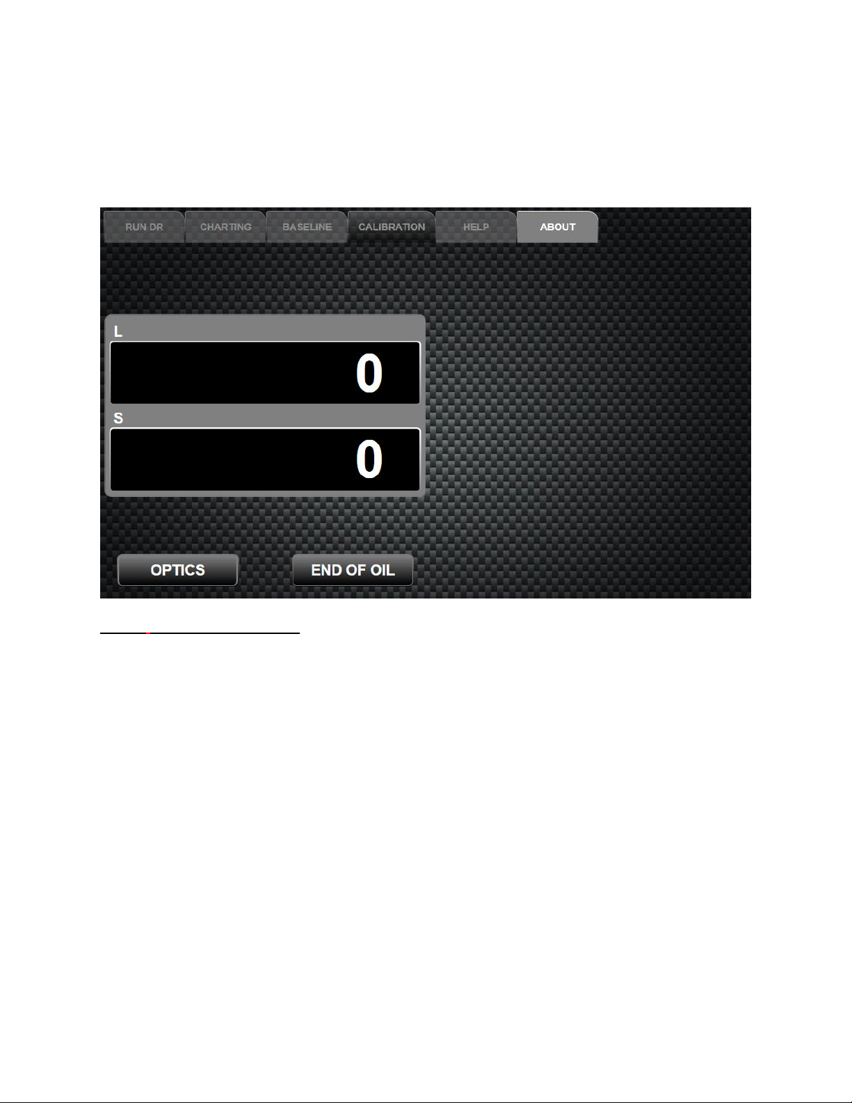
7.6 – ABOUT Tab .....................................................................................................................................22
8. Downloading and Understanding DR Data .........................................................................................23
8.1 – Quantifying DR Data....................................................................................................................... 23
8.2 – DL and DSReadings ......................................................................................................................... 26
9. Maintaining the DR-7.......................................................................................................................... 27
9.1 – Sensor Cleasning ............................................................................................................................ 27
10. Limited Warranty ................................................................................................................................28

Page 3 of 28
1. Introduction
The Direct Reading Ferrograph is a trending instrument, providing readings which measure the amount of
metallic particles, both large (DL) and small (DS) in a known oil sample. The numbers given do NOT
relate to any other numbers such as parts per million (ppm). The DL and DS numbers of the DR-7 will
correspond to those reading generated by a DR-5 and will be slightly higher than a DR-3. In turn these
numbers can be used to calculate the wear particle count (WPC).
The DR-7 is much more versatile than its predecessors. Running on a Windows platform allows users to
quickly upgrade DR software to the latest version, interface through the internet, and set up e-mail
capabilities. The USB connections can easily be used to set up multiple DR-7 units together and connect
to the user lab software. The provided Ethernet port allows users to network into their current systems and
to each externally.
The first Direct Reading Ferrograph was developed in the early 1970’s as the whole science of
Ferrography was being developed under a contract with the US Navy. Early DR Instruments were large
and had to be adjusted before every test. The large density particles and small density particles had to be
read separately by turning a switch. Over the years, the Direct Reader (DR) progressed from the original
manual instrument to a Duplex. The Duplex was a manual DR with a Ferrogram Maker in the same
instrument. The DR-2 was the next version which contained the first attempt at a self-adjusting
instrument. Throughout the years the DR-3, DR-5 and DR-6 series of Instruments were created, finally
with this current DR-7 design.
During the development of the Ferrography instruments, it was discovered the most sensitive locations for
detecting a changing wear situation were found, this point was determined to be at the entry point of the
magnets, at a position approximately 5 millimeters downstream. Particles of 5 microns or greater
collected at the entry point. Particles with the size of 1-2 microns collect at the 5 mm position.
Accordingly, the Direct Reader Ferrograph was designed to quantify particles into these two size ranges.
This is where the Density Large (DL) and Density Small (DS) numbers come from. These densities are
found by shining a monochromatic light through the bottom of the glass part of the precipitator tube. The
amount of light cut off by the particle builds up in the glass tube, and therefore blocks the sensors, and
this blockage is read by sensors. The DR then converts this attenuated light into the DL and DS readings.
The digital output has a range of 0 to 190 units. A reading of 100 units corresponds to approximately one-
half of the area covered and is the recommended upper limit. For readings greater than 100, the
instrument response is non-linear due to the particles piling on top of one another so that less light is
attenuated. Trico recommends not using a reading over 90 and the instrument indicates a warning
message to indicate that the sample should be diluted.
Because this is a trending instrument, results on the same sample will vary due to accuracy of sample
preparation, sample temperature, settling of the particles, and other factors. Comparative unit testing
proves that a given sample can produce results repetitively within a range on a single DR-7 and across
multiple units.

Page 4 of 28
2. Packing List and Assembly
After receiving the DR-7, check the package for any shipping damage, and report the damage to the
carrier that delivered the package to you. Shipping damage is the receiver’s responsibility.
Packing items:
1 – DR-7 Direct Reading Ferrograph Unit 1 – Universal Power Cord
1 – Stainless Steel Sample Vial Holder 1 – Spare 1A Fuse
1 – Stainless Steel 125 ml Beaker 1 – DR-7 User’s Manual
3 – Spare “End of Oil Sensor” Doors 1 – Calibration Tube PN: 43021
2.1 – DR-7 Unit Assembly
Required tools for Assembly:
1 – #2 Philips Head Screwdriver
1. Remove the 125 ml beaker from the packing paper. Place the beaker into the recessed cup for waste
collection.
2. The drain tube on the right (facing the instrument) bulkhead should be placed into beaker. During
factory conformity testing a test liquid is circulated through the pump tubing to verify function and
check units for leakage. Excess fluid may still be in the tubing upon arrival. After time the drain tube
will become hard and brittle. A new tube can be attached using the tubing cut from a used precipitator
tube as a replacement.
3. Remove the two screws from the top of the instrument where the vial holder goes. Place the stainless
vial holder on top of the tower with the fingers pointing toward you and thread the two screws back
into the holes at the top left side of the Instrument. Tighten the screws using a #2 Phillips head.
4. Plug the universal power cord into the back of the DR-7 into the power jack and then into an
electrical outlet.
NOTE: If the electric supply is other than 120v, 60/50 Hz, the standard Universal Power Cord
provided will need to be replaced or adapted to the host country’s receptacle. Ensure that the power
supplied is within the range outlined in the specifications of this manual. It is the user’s responsibility
to supply the correct plug for the available power. Install the correct plug, then plug the power supply
into the back of the DR-7 and then into the electrical outlet.
To lift and move the DR-7, turn off the instrument and disconnect the power cord and the computer cable,
if attached. Place your hands under the instrument two thirds of the way back and lift. This will balance
the instrument while lifting.

Page 5 of 28
3. Specification and Operating Parameters
Physical Specifications
Length (Front to Back):
9.00 in.
22.8 cm
Width (Side to Side):
12.00 in.
30.5 cm
Height:
19.75 in.
50.2 cm
Weight (Instrument Only):
13 lbs.
5.9 kg
Power
Voltage:
100-240V AC
Frequency:
50/60 Hz
Amperage:
1A
Instrument contains a 1A power fuse located at the power plug inlet
Hardware
Operating system:
Windows 10 IoT
Memory:
64 GB Flash
External USB Ports:
2 x USB “A”
Ethernet Connection:
RJ45 cat 5
RAM:
4 GB DDR2 RAM
Processor:
Intel® Celeron® CPU N2807 @ 1.58 Ghz
Environmental Conditions
For indoor use on a solid level surface without movement or vibration.
Use in a well-ventilated area.
Room temperature:
50ºF to 85ºF
10ºC to 29ºC
Humidity:
5% to 50% non-condensing
CAUTION: DO NOT operate the DR-7 with the back panel removed. Unplug the DR-7 from the power
supply before removing the back panel for adjustments. Check with Trico before removing as this could
void the unit warranty. All other repairs must be done at the factory.
Page 6 of 28
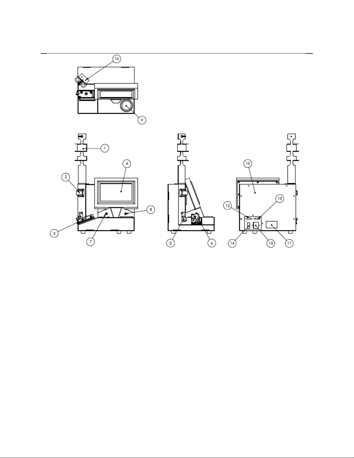
4. DR-7 Nomenclature
This section introduces the user to the major components of the DR-7 Direct Reading Ferrograph
Instrument. The following subparagraphs discuss the major components, their location, and the
nomenclature for each item on the DR-7 Direct Reading Ferrograph Instrument shown above.
1) Vial Holder: Holds two sample vials and mounts on the top of the DR-7 with two screws. Do not use
this as a handle to pick up the unit.
2) End of Oil Sensor: The end of oil sensor will sense the meniscus created in the precipitator capillary
tubing when the test is completed, automatically freezing the DL and DS readings. The DR-7 will
record the readings if the sensor is bypassed by pressing the STOP button when the technician
determines that the test is completed.
3) Tubing Guide: Used to bend and guide the capillary tubing without kinking from the vertical position
to the inclined magnet assembly. Tubing is held in place by weaving it through the three pins.
4) LCD Screen: This touch screen displays the set up and operational screens which have several options
available besides the calibration menu.
5) Optics Assembly: Holds the glass precipitator tube assembly.
6) Magnet Assembly: Magnets designed to attract the ferrous particles on the bottom of the glass
precipitator tube to obtain the DL and DS readings.
7) Left Bulkhead: Where the end of the precipitator tube connects to the pump head.

Page 7 of 28
8) Right Bulkhead: The drain connects here and goes into the waste beaker. Drain tubes can be made by
taking the tubing off the end of a used precipitator tube.
9) 125 ml Waste Beaker: Used to catch the used oil. Discard the mixture of oil and solvent properly
when nearing the end of the drain tube.
10) Back Cover: Removable with eight (8) screws. Check with the factory before removing as this
could void the unit warranty.
11) Windows Product ID Number/ DR-7 Model and Serial Number: The Windows Product ID
number is located on the back of the unit and is used for Windows product support through Microsoft.
The DR-7 Model, and Serial Number Label is located on the bottom or back of the unit and used when
calling Trico for DR-7 support. Record these numbers on the DR-7 user manual for future reference.
12) Ethernet Network Jack: Ethernet cable may be used to download the DR-7 data to a database
and utilize internet/ intranet Windows functions.
13) Power Input Jack: The standard universal power cord supplied with the unit is first plugged into
the power input jack and then plugged into the power receptacle that supplies appropriate power within
the unit specifications.
14) On-Off Power Rocker Switch: Red indicates “ON” position, black indicates “OFF” position.
15) USB Ports: External peripheral devices such as the provided mouse, keyboard or monitor may be
utilized through the USB connections, provided they are compatible with Windows.
16) Vial Mounting Screw Location: During assembly, screws provided with the unit are threaded
into the top location shown to hold the vial assembly onto the unit.
NOTE: Tampering with the Instrument will void the warranty.

Page 8 of 28
5. Consumables and Accessories
It will become necessary to reorder the consumables to continue testing on the DR-7 unit. This section
contains reordering information. Many of the test equipment items should not be reused. Contaminated
devices can cause inaccurate or incorrect interpretation.
Part # 73-0050 Pipette Tips- GLASS (Package of 200) – Disposable glass tips used with the pipettor.
Part # 73-0060 Sample Vials (Package of 250) – Disposable glass vial holds the oil and heptane and fit
properly into the vial holder.
Part # 73-0090 Sample Vial Rack – Will hold up to 18 sample vials in preparation for testing.
Heptane – A filtered solvent used to thin the oil sample for testing to run through the precipitator tube at
a quicker rate. The fixer can be used to clean between the optics assembly and magnet assembly. This
solvent is non-carcinogenic, but flammable. (n-Heptane 99+% for Spectrophotometry can be purchased
from VWR at https://us.vwr.com or call 1-800-932-5000)
Part # 74-0020 Diluent Oil – Used when the oil sample tested exceeds a DL or DS reading of 90 or more
and the sample must be diluted to get a reading under 90 units.
Part # 74-0040 Precipitator Tubes (Package of 250) – This disposable tube carries the oil sample from
the sample vial, over the magnet assembly to the waste bottle. The precipitator tube is constructed of four
parts. The first is a 33” piece of capillary tubing. This runs into a 4-inch piece of glass and is held in place
by a black shrink tube. A piece of tygon tubing is added to the other end of the glass to connect the glass
tube with the left bulkhead.
Part # 74-0250 Grease Solvent – An agent used to dissolve grease into a form that can be tested with the
DR-7 unit.
Part # 75-0010 Bottle Top Dispenser, 1 ml – Use in the fixer bottle to dispense one milliliter of heptane
with each pump.
Part # 75-0030 Pipette Dispenser (Pipettor) – Used to draw one milliliter of the oil sample for the test.
Part # 75-0040 Pipette Tips- PLASTIC (Package of 250) – Disposable plastic tips used with the pipettor.
Part # 76-0030 Wear Particle Atlas – A guide to wear particle identification containing photographs of
critical wear particles found in used lubricating oil, illustrative case histories, and operational procedures
for wear debris analysis.
Part # 43021 DR-7 Calibration Tube - Used in calibration procedure to correct unit light intensity
output.
Part # DR-7FIL - Used for calibration purposes on the DR-7 to confirm the calibration and alignment
readings over time.
NOTE: Part # 73-0060, Part # 74-0040, and Part # 73-0050 must be discarded after one use in order to
eliminate cross contamination.
CAUTION:Heptane and Part # 74-0250 Grease Solvent are considered hazardous materials and should
be handled with caution and disposed of properly. Consult the Safety Data Sheet (SDS) enclosed with
these chemicals for more information.

Page 9 of 28
6. Oil Sample Preparation
6.1 – Preparing an Oil Sample for Testing
Gravimetric settling of wear particles in lubricating oil starts immediately after a sample is left standing.
To obtain a representative sample from a larger sample, the particles must be evenly dispersed. To make a
homogenous mixture, the following procedure is recommended:
1. The oil should be in a clear container to allow for observation of the oil and large contaminants. Make
sure the container is two-thirds full to allow for agitation to completely mix the particles into the oil,
thus giving the sample a homogenous mixture.
2. Heat the oil to approximately 150°F (65°C). This is according to ASTM standard procedure to keep
the particles suspended as long as possible.
3. Remove from the heat source and vigorously shake the bottle.
4. With the pipettor and clean pipette tip, remove 1 ml of oil and dispense into a clean sample vial.
5. Add 1 or 2 ml of heptane to the 1 ml of oil in the sample vial. The viscosity of the oil determines the
amount of heptane added to the oil in the sample vial. For high-viscosity fluids add 2 ml of heptane to
reduce the viscosity. This will allow the viscous oil to flow along the precipitator tube at a similar rate
as lower viscosity fluids. For low-viscosity fluids 1 ml of heptane is enough to provide fluid flow
through the precipitator tube. It does not matter if 1 or 2 ml of heptane is used, as long as the required
1 ml of oil is used for each test. However, higher viscosity samples moving at too slow of a rate will
affect particle deposition by increasing the amount material deposited on the DL compared to the DS.
6. The quicker a sample is tested, the better the results. Allowing the sample to settle in the test vial may
cause bunching of particles in the precipitator tube since most of the material will be collected at the
bottom of the vial and deposited in the precipitator tube around the DL sensor. To avoid this, use the
prepared sample as soon as possible or re-mix the sample before testing so that wear particles are
properly dispersed.
6.2 – Dilutions
Readings on the DR-7 greater than 90 in the 1:1 or 1:2 dilution modes are not linear due to the particles
piling on top of one another. When the DR-7 readings reach 90, the test is invalid and should be repeated
using a dilution of the base sample.
1. To prepare dilutions, start with the base mixture. In a clean sample vial, place 1ml of the base
mixture. To this add 9 ml of diluent oil. This will make a 10:1 dilution.
2. In another clean sample vial, place 1ml of the 10:1 dilution. To this, add the heptane as done to make
the base solution (1 or 2 ml). This is the 10:1 sample to be run on the DR-7.
3. On the RUN DR tab MENU display, change the dilution ratio to 10:1 and the readings will be
corrected for this dilution. The upper limit will automatically be changed to 900 instead of 90. If the
DL and DS readings go over 900 a 100:1 dilution must be made.
4. To make a 100:1 dilution, start with 1 ml of the 10:1 dilution and add 9 ml of the diluent oil. Take 1
ml of this dilution and the standard amount of heptane in a clean sample vial to run the 100:1 dilution.
Change the dilution ration to 100:1 in the menu so the final DL and DS readings will be corrected for
the dilution and the upper limit of the test will be changed to 9000.
5. When the dilution factor is changed, the DR-7 will automatically multiply the DL and DS readings to
give you the correct dilution readings and the limits of the test will be increased. This means that in a
normal test the display will warn the user if the reading goes over 90. In a 10:1 dilution, that number
increases to 900 if the DR-7 is set at that dilution ratio. The 100:1 would have a high limit of 9000.
NOTE: If the dilution factors are not changed in the menu, the DL and DS readings must be multiplied
by the dilution factor to get the correct readings. In a 10:1 dilution the DL and DS readings would have to
be multiplied by 10.
Page 10 of 28
7. Operating Procedures
Always use the DR-7 on a sturdy, level surface in a well-ventilated room. To start the DR-7 system, flip
the rocker switch on the back of the unit to the “ON” position. The operating system will automatically
start booting and the Trico logo will illuminate. Once the windows system has booted the DR-7 program
will automatically open to the RUN DR tab, otherwise there is a shortcut on the desktop to launch the
DR-7 program.
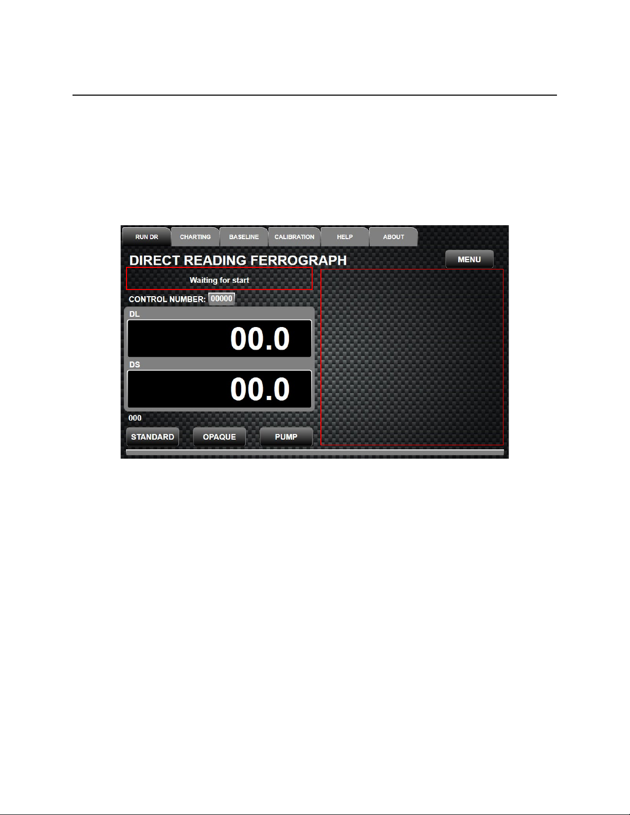
At system startup the main DR-7 menu appears. The first start up screen is shown below. This start up
screen allows the user to quickly change settings, calibrate optics or end of oil sensor or start the testing
process. At the very top of the main menu six tabs appear: RUN DR, CHARTING, BASELINE,
CALIBRATION, HELP, and ABOUT, which are explained in further detail.
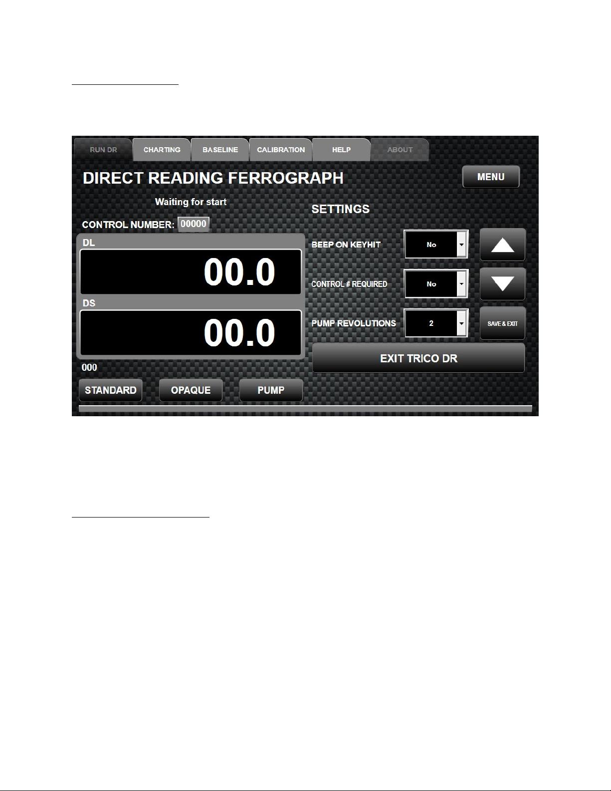
7.1 – RUN DR Tab
The Run DR tab is the functional work areas for operating the DR-7 system and allows users to change
settings on the fly, or operate the program and circulate the pump.
Located on the right side of the RUN DR tab is the Submenu Selection Area. In this area all sub menues
will appear when the MENU, STANDARD, or OPAQUE buttons are selected.
In the left half of the screen two black blocks appear indicating the DL and DS numbers during the test.
Above these blocks, system messages will appear prompting the user or indicating warning messages
when parameters are out of range.
Three touch buttons are also located at the lower left side of the screen under the DL and DS reading
boxes. These buttons allow the user to start tests using the STANDARD or OPAQUE functions. By
pressing these buttons, a new menu appears in the submenu selection area for running the specific test.
The PUMP button, when pressed rotates the peristaltic pump one revolution and can be used to start the
sample flow through the precipitator tube if the sample viscosity is too high and flow is unable to be
achieved through the current rotation settings. The PUMP button should only be used to start the flow and
should not be continually used to process the sample at a faster pace. Doing so will give false DL and DS
readings because of inconsistency of flow over the magnet assembly.
Submenu Area

Page 11 of 28
The DR-7 displays the time (in seconds) that each sample takes to complete. The sample time is defined
as the time required from when the DR-7 detects the oil at its DL and DS sensors, to the time the last of
the oil passes the end of oil sensor. The timer is located under the DL and DS blocks just above the
STANDARD button indicated as 000.
Knowing the time each sample takes to complete can be used to catch a bad sample test. For example, if
previous samples required an average of 200 seconds to complete and the next sample, of the same oil,
requires only 100 seconds, the sample test is in error and must be repeated. Sample times will vary
somewhat, however, significant differences in time are usually caused by false tripping of the end of oil
sensor by a large particle in the sample. This requires adjustment to the end of oil sensor’s threshold or
bypassing the End of Oil Sensor by leaving the capillary tube outside of the sensor during the test. See the
END OF OIL SENSOR CALIBRATION in section 8. Calibration of this manual. The time will retain the
last sample time until the next sample is started.
If, for some reason, a sample is running through the precipitator tube for 12 minutes, the DR-7 will end
the test and freeze the readings at this time. “TIMED OUT” will appear next to the timer below the DL
and DS boxes. This might be caused by the sample being too viscous. The sample should be thinned with
more heptane or diluent oil and run again for accurate results.
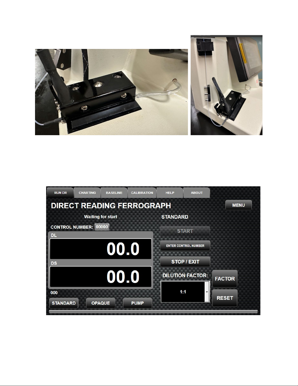
7.1.1 – STANDARD Operation
The black shrink tubing should be placed against the left edge of this assembly to run the test to ensure no
light intrusion. A depress lever is located to the left of the optics assembly to open and hold the
precipitator gate in the up position to allow for the precipitator insertion under the optics. Moving the
lever forward opens the gate while moving the lever back will close the gate. When closing the gate, the
lever should be pushed back until its stops which will clamp and hole the precipitator tube.
1. Mix the oil sample as described in section 6.1 Preparing an Oil Sample for Testing of this manual.
Put the sample in the vial tube holder at the top of the instrument.
2. Install a precipitator tube by first moving the depress lever forward on the left-hand side of the optics
assembly to open and hold the precipitator gate in the up position. Insert the glass part of the
precipitator tube under the optics block and then move the lever backwards while pressing down on
the gate until its stops to hold the precipitator tube in place. The black shrink tubing of the precipitator
tube should be tight against the left-hand side of the Optics Block. Next, place the short end of tygon
tubing onto the barb fitting on the left bulkhead barb under the display screen.
3. Weave the capillary tube between the tubing guide pins as shown below. Weaving the tube through
the pins will help keep the precipitator tube from sliding out of position. Then place the capillary tube
in the center groove of the end of oil sensor and close the door by snapping it shut. Be careful not to
pinch the tubing with the door.
Page 12 of 28
4. Place the end of the capillary tube in the oil sample in the vial holder until it touches the bottom of the
sample vial and press the tubing into the spring at the top of the sample vial holder to hold the tubing
in place.
5. Press the STANDARD button.
a. “YES” Control Number is Required in MENU Settings
i. A system message will indicate that the user will need to enter a control number for
the sample and the START button will be gray and un-selectable.
ii. Press the ENTER CONTROL NUMBER button and the keypad will now appear.
iii. Enter the control number. Make sure the control number is correct and press ENTER,
otherwise press CLEAR to clear out the control number to enter a new one. Entering
a control number will store the data into a coma separated values (csv) file, in which
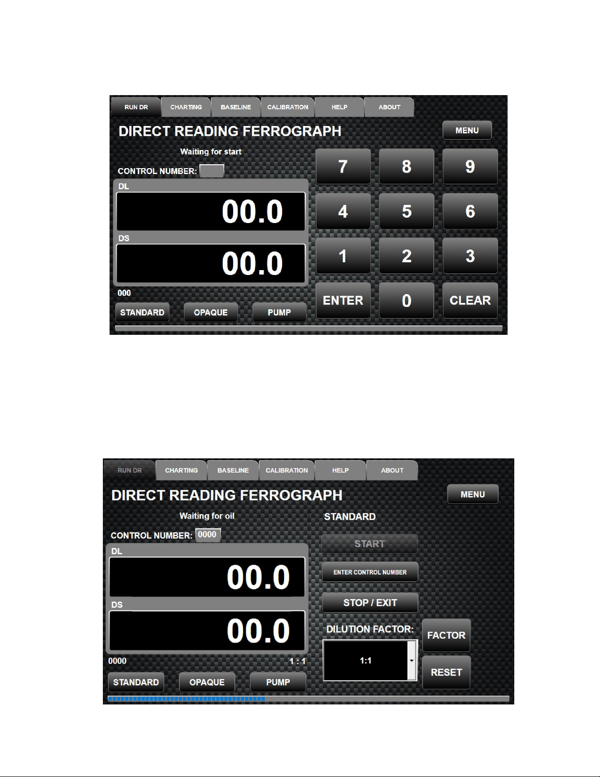
Page 13 of 28
a script can be written to load the data into a given lab data tracking software or
spread sheet.
iv. After ENTER has been selected the keypad will disappear and the RUN DR will
again be displayed.
6. Press START and the unit will begin the test until it is completed. When pressed the pump activates
and starts the siphoning effect in the precipitator tube. For full suction to begin, the oil level in the
precipitator tube must flow past the bottom of the vial in the vial holder. If this does not happen the
viscosity of the solution is too viscous, and the PUMP button can be pressed until flow starts. The
default for pump revolutions is set at 2 and can be changed by changing the settings in the MENU.
Thin oil samples only need one revolution of the peristaltic pump to start the flow. Thicker oil
samples need two or more revolutions of the pump, or heptane can be added to thin the solution.

Page 14 of 28
7. As oil flows through the precipitator tube, the Display Messages will change through the following
phrases, colored white, letting the operator know the progression of the test.
•Waiting for Start
•Waiting for Oil
•Oil – Start Testing
•Waiting on End of Oil
•Done – Waiting for Start
8. When DONE – WAITING FOR START appears the DL and DS readings will be frozen. This is
when the DL and DS readings are recorded for the oil sample; but only if a control number was
entered for the sample. This data is written to the DR-7 data folder of the program and can be
accessed through windows explorer under the C:\Programs\Trico folder. If downloading data, your
software will need a script written to pull this data from the file. Files are named per control number
along with a date time stamp.
9. This completes a STANDARD test, and another test can then be performed. Remove the used
precipitator tube and install a new one for the next test to give accurate results.
NOTE:While the test is running the precipitator tube should not be moved or readjusted in the holder.
Doing so will give false readings and inaccurate results. If a problem occurs remove and discard the
precipitator tube and oil sample to begin a new test.
7.1.2 – OPAQUE Operation
An opaque sample is defined as one which is too dark to read under the optical sensors. Usually, samples
filled with carbonaceous material produce a reading of 190 in one or both sensors as soon as they start to
flow through the glass section of the precipitator tube. These dark particles cut off all the monochromatic
light going to the sensors. Diesel oil is a good example of an opaque sample. If an opaque sample is run
as a regular sample on the DR-7, the top line of the display will read TOO DARK – USE OPAQUE.
A special procedure is used to test opaque samples. Filtered heptane is run through the DR-7 to establish a
baseline for the wash fluid. The opaque sample is then run using the same precipitator tube. After the oil
has drained from the sample vial, heptane is used again to wash out the dark oil in the precipitator tube
while the magnet assembly holds the metallic wear particles in place to provide the actual DL and DS
readings.
The first time the DR-7 is used for an opaque test, you are prompted to perform a baseline test using
heptane. This baseline will stay in the DR-7’s memory until the program is shutdown. A sample vial of
the heptane does not have to be run at the beginning of every test for a baseline, just at the end to wash
away the dark oil.

Page 15 of 28
Running an Opaque Sample:
1. Press the OPAQUE button.
2. Enter the control number, if used, by pressing the ENTER CONTROL NUMBER button, as
explained in the Standard Operation section.
3. Pump 4 ml of heptane into a clean sample vial to be placed in the vial holder on top of the DR-7 next
to the prepared oil sample.
4. A base line must be created the first time an opaque sample is run. Place the small end of the
precipitator tube in the sample vial of heptane and press RUN BASELINE.
5. When the DR-7 is calibrated on the heptane, the pump will reverse and shut off the flow of the
heptane. At this point change the precipitator tube to the sample vial with the oil sample, inserting the
tube all the way to the bottom of the sample vial. Press the START button and this starts the flow
again.
6. When the last of the oil sample is in the precipitator tube, quickly move the tube to the vial that
contains the heptane. This will wash the dark material out of the precipitator tube, and you will get
the actual DL and DS readings. By moving the precipitator tube in and out of the heptane, air bubbles
will be introduced into the capillary tube. These bubbles will help remove the opaque oil and
nonmagnetic material in the precipitator tube.
7. When the heptane is gone and the flow has stopped in the capillary tube, take the DL and DS
readings. Press the COMPLETE button to save these readings.
8. To start another opaque test. Place a newly prepared sample into the vial holder along with a sample
vial of heptane for washing. Replace the precipitator tube and place the capillary tube end into the
new sample and then push the START button again to use existing baseline that was established with
the first opaque test. Run this test with the capillary end of the precipitator tube in the oil sample
transferring it to the heptane at the end of the test to flush the precipitator tube and obtain the DL and
DS readings.
9. To end the OPAQUE operation press STOP to exit out.
Page 16 of 28
7.1.3 – MENU Button
The MENU button is in the upper right corner of the RUN DR tab. By pressing this button, the DR-7
settings menu appears in the Submenu Selection area. Different settings can be selected from the pull-
down menu to control beep on key hit, if a control number is required per sample before testing, and the
number of pump revolutions to start suction during a test.
Selections can be made by touching the desired setting pull down and hitting the up or down arrows to the
side to scroll through the selections. After all changes are made press the SAVE & EXIT button to set the
new selections and then exit to exit out of the menu. Default settings are, Beep on key hit: No, Control
number required: No, Pump revolutions: 2.
7.1.4 –Shutdown Procedures
To close the DR-7 program and exit to Windows, enter the MENU Screen under the RUN DR Tab and
press the EXIIT button. In doing this the user enters the Windows Desktop screen. Here is all of the
functions of a normal Windows based operating system. To shut down the power fully, either use the
shortcut on the desktop, or go to the start menu and click on shutdown to close the operating system. This
may take a few seconds to close windows applications and fully shut down.
Once the operating system is fully shut down and the touch screen turns black the user may flip the rocker
switch on the back of the unit to the “OFF” position. By turning the power off, the illuminated Trico logo
will dim to black.

Page 17 of 28
7.2 – CHARTING Tab
The Charting Tab is the function that will plot the DL and DS. Pressing GENERATE GRAPHS button
will graph the L and S Base levels and L and S Count levels over time. Pressing CLEAR GRAPHS then
clears all the data from the graph.
7.3 – BASELINE Tab
The Baseline Tab is used when runing Opaque samples and is covered under the Opaque Operation
section. Values are never input into this tab.
Page 18 of 28
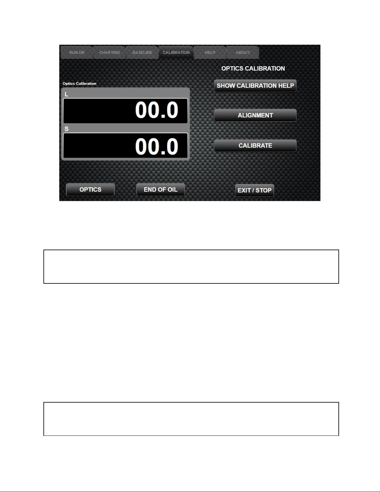
7.4 – CALIBRATION Tab
The DR-7 has two calibration features OPTICS calibration and END OF OIL sensor calibration located in
the CALIBRATION tab. This helps maintain optimum performance during operation. This is controlled
by the lab technician when maintenance and cleaning is performed or performed on a routine basis before
sample testing. These features are in place to allow the equipment to be in service for lengthy periods of
time without the need to ship the unit back to the factory for optics cleaning or optics calibration.
7.4.1 – OPTICAL Calibration
The optics guide block is aligned with the LED light source during factory alignment calibration. Unlike
previous DR versions, the optics block should never be removed for cleaning (see section 9 Maintaining
the DR-7). The new design of the Optics block uses a special fluid filled calibration tube for both the
alignment procedure during the factory build, and in calibrating the LED light source by the lab
technician.
The LED light source calibration should be done daily, or every time the instrument is turned on. This is
done by selecting the OPTICS button in the CALIBRATION tab. In the process, the fluid filled
calibration tube is used to focus light changes in the instrument. In addition, an OPTICAL CALIBRATION
CHECK is used to check the optical calibration to ensure the unit falls within a specified range. This
check should be performed monthly if the unit is used frequently. Although increased sensitivity has been
enhanced throughout the development of this instrument, because of particle distribution and other
variables within the oil sample being tested, the DR-7 is still considered a trending instrument.
Page 19 of 28
To calibrate the LED light source in the OPTICS submenu:
1. Insert the Optics Calibration Tube (Part #43021) supplied with the unit by lifting the gate and placing the
tube under the optics sensor. Close the gate and ensure the Calibration tube protrudes evenly from both
ends of the optics block.
NOTE: The tube should be wiped down to clean fingerprints or smudges from the glass. Before
inserting the tube, inspect the tube for air bubbles which could affect the reading. If air bubbles are
present in the area to be inserted into the sensor path, place the calibration tube back into the holder and
stand it upright to allow air to move to the top end of the glass tube.
2. Select the CALIBRATION tab.
3. Press the OPTICS button.
4. Press the CALIBRATE button in the submenu. The DR-7 will automatically calibrate the light intensity
by determining the maximum intensity and then balancing the optical channels to a predetermined offset
to produce the most effective results.
5. After the Calibration is finished the numbers in the DL and DS will read around 2550 and the message
will appear "Complete" in the message area.
6. Press EXIT/STOP to save the calibration.
7. Remove the Calibration tube and place it back into the holder, then press the RUN DR tab to return to
the test area.
NOTE: The ALIGNMENT button is used only by factory technicians to mechanically align the optics
to the light source. Users do not need to use this feature. Accidently pressing the button will not affect
the instrument readings. Allow the alignment program to reach its target and then press the EXIT/STOP
button. Then conduct the LED light source calibration outlined in the steps above.
Page 20 of 28
7.4.1.1 – Optical Calibration Check with Trico #DR7-FIL
Optical Calibration Checks are performed on the DR-7 optics using the neutral density films and
calibration tube purchased separately in the DR-7 Neutral Density Calibration test kit, Trico Part # DR7-
FIL. Following this procedure will check the optical sensors are within limits and the correct readings are
being obtained from the instrument. The test kit comes with three specific neutral density filters used in
the development of the DR instruments. Neutral density filters can vary in density range, use only those
filters provided in the test kit which have been specifically graded for the purpose of the DR calibration
check. Neutral Density films can vary due to manufacturing variances, and each kit should be measured to
establish its own set of calibration numbers. Follow the calibration guild provided with the Calibration
test kit to refine reading ranges.
NOTE: Neutral density filters should be handled with care. Fingerprints, smears, or scratches will change
the calibration readings. Density filters from older model DR's can still be used on the DR-7. However,
note the changes in instrument reads in the table below.
Checking Optical Calibration:
1. Make sure the Optics block and photocell area is clean and free of dirt and oil.
2. Insert the glass Calibration tube (PN:43021) from the calibration kit into the optics by pressing the
lever forward on the left side of the optic block, lifting the gate and then sliding the calibration tube
into place.
3. On the RUN DR tab press STANDARD and then START. Enter a false control number if needed.
4. Insert a filter under the sensor area and quickly remove it.
5. The screen will now say “Oil- Starting Test”. Wait for this message to change to “Waiting on End of
Oil” and then insert the filter under the sensors again and hold steady until the readings stop climbing.
6. Record the reading.
7. Repeat the same procedures for the two other density filters.
NOTE: When inserting and removing density films, failure to remove films during sensor
zeroing will cause L and S reading to output 30 units lower than expected since sensors will zero
on the density filter.
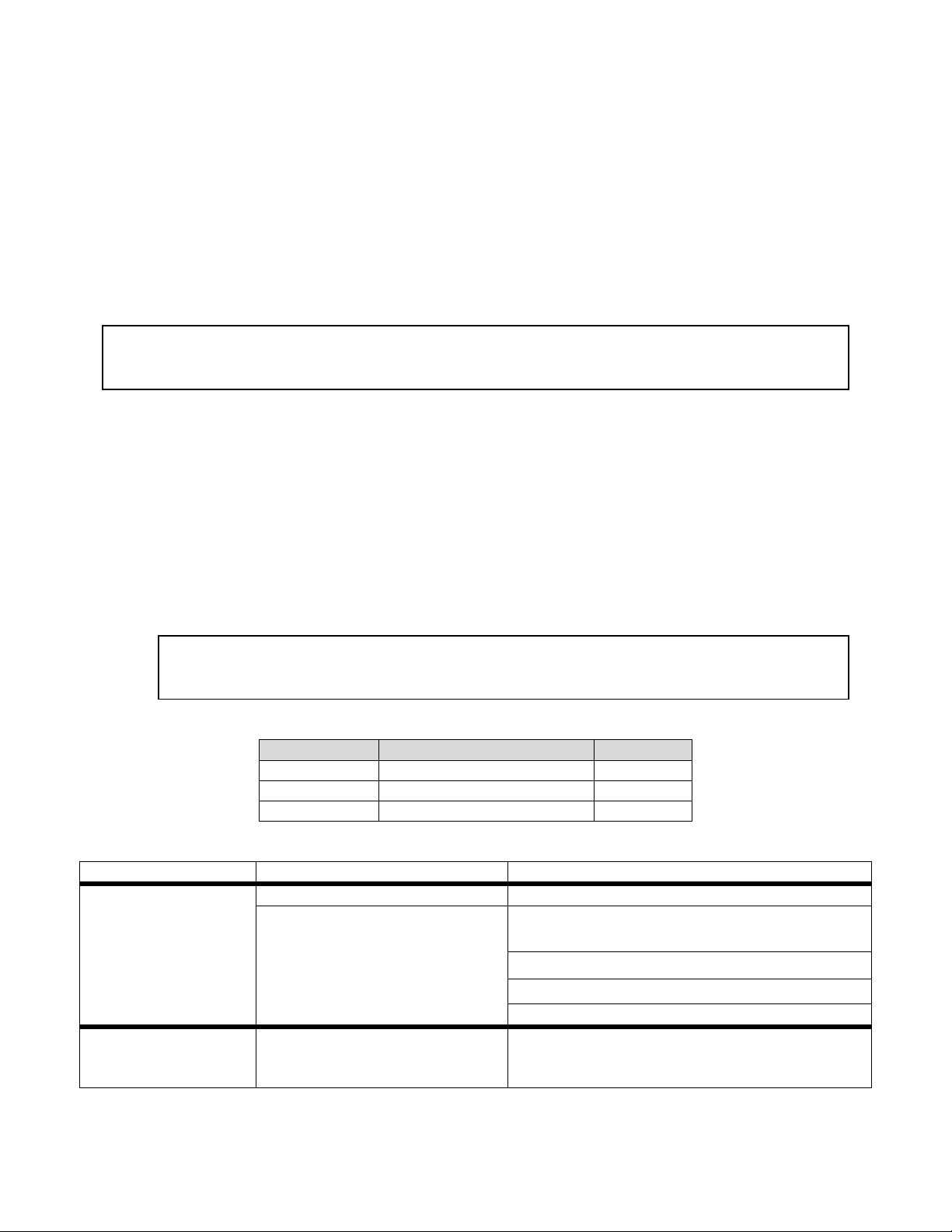
Typical neutral density filter reading ranges for the L and S:
Filter Density
L/ S Typical Mean Reading
L/S Range
.10
35
31-42
.20
66
60-74
.30
89
81-98
Calibration Check Troubleshooting:
Issue
Reason
Solution
All density filter
values out of range
Values out of range <10 units
Recalibrate LED light source and recheck
Value out of range > 10 units
Optical sensor zeroed on density film, repeat
check following procedure
Recalibrate LED light source and recheck
Photocell detector faulty, replace photocell
Optics block out of alignment, consult Trico
Only one density filter
value out of calculated
range
Value out of range <10 units Check density film for scratches, smears, or
fingerprints
Table of contents
Other Trico Measuring Instrument manuals


