TRIGA TR-FFT User manual

A
P/N LS10309-001TR-E:A • ECN 151608
Document LS10309-001TR-E
04/28/2021 Rev:
Fire Fighter’s Telephone
TR-FFT
Installation/Operation Manual

2 PRELIMINARY: TR-FFT Fire Fighter’s Telephone Manual — LS10309-001TR-E:A 04/28/2021
Fire Alarm & Emergency Communication System Limitations
While a life safety system may lower insurance rates, it is not a substitute for life and property insurance!
An automatic fire alarm system—typically made up of smoke
detectors, heat detectors, manual pull stations, audible warning
devices, and a fire alarm control panel (FACP) with remote
notification capability—can provide early warning of a developing fire.
Such a system, however, does not assure protection against property
damage or loss of life resulting from a fire.
An emergency communication system—typically made up of an
automatic fire alarm system (as described above) and a life safety
communication system that may include an autonomous control unit
(ACU), local operating console (LOC), voice communication, and
other various interoperable communication methods—can broadcast
a mass notification message. Such a system, however, does not
assure protection against property damage or loss of life resulting
from a fire or life safety event.
The Manufacturer recommends that smoke and/or heat detectors be
located throughout a protected premises following the
recommendations of the current edition of the National Fire Protection
Association Standard 72 (NFPA72), manufacturer's
recommendations, State and local codes, and the recommendations
contained in the Guide for Proper Use of System Smoke Detectors,
which is made available at no charge to all installing dealers. This
document can be found at http://www.systemsensor.com/appguides/.
A study by the Federal Emergency Management Agency (an agency
of the United States government) indicated thatsmoke detectors may
not go off in as many as 35% of all fires. While fire alarm systems are
designed to provide early warning against fire, they do not guarantee
warning or protection against fire. A fire alarm system may not
provide timely or adequate warning, or simply may not function, for a
variety of reasons:
Smoke detectors may not sense fire where smoke cannot reach the
detectors such as in chimneys, in or behind walls, on roofs, or on the
other side of closed doors.Smoke detectors also may notsense a fire
on another level or floor of a building. A second-floor detector, for
example, may not sense a first-floor or basement fire.
Particles of combustion or “smoke” from a developing fire may not
reach the sensing chambers of smoke detectors because:
• Barriers such as closed or partially closed doors, walls, chimneys,
even wet or humid areas may inhibit particle or smoke flow.
• Smoke particles may become “cold,” stratify, and not reach the
ceiling or upper walls where detectors are located.
• Smoke particles may be blown away from detectors by air outlets,
such as air conditioning vents.
• Smoke particles may be drawn into air returns before reaching the
detector.
The amount of “smoke” present may be insufficient to alarm smoke
detectors. Smoke detectors are designed to alarm at various levels of
smoke density. If such density levels are not created by a developing
fire at the location of detectors, the detectors will not go into alarm.
Smoke detectors, even when working properly, have sensing
limitations. Detectors that have photoelectronic sensing chambers
tend to detect smoldering fires better than flaming fires, which have
little visible smoke. Detectors that have ionizing-type sensing
chambers tend to detect fast-flaming fires better than smoldering
fires. Because fires develop in different ways and are often
unpredictable in their growth, neither type of detector is necessarily
best and a given type of detector may not provide adequate warning
of a fire.
Smoke detectors cannot be expected to provide adequate warning of
fires caused by arson, children playing with matches (especially in
bedrooms), smoking in bed, and violent explosions (caused by
escaping gas, improper storage of flammable materials, etc.).
Heat detectors do not sense particles of combustion and alarm only
when heat on their sensors increases at a predetermined rate or
reaches a predetermined level. Rate-of-rise heat detectors may be
subject to reduced sensitivity over time. For this reason, the rate-of-
rise feature of each detector should be tested at least once per year
by a qualified fire protection specialist. Heat detectors are designed to
protect property, not life.
IMPORTANT! Smoke detectors must be installed in the same room
as the control panel and in rooms used by the system for the
connection of alarm transmission wiring, communications, signaling,
and/or power. If detectors are not so located, a developing fire may
damage the alarm system, compromising its ability to report a fire.
Audible warning devices such as bells, horns, strobes, speakers
and displays may not alert people if these devices are located on the
other side of closed or partly open doors or are located on another
floor of a building. Any warning device may fail to alert people with a
disability or those who have recently consumed drugs, alcohol, or
medication. Please note that:
• An emergency communication system may take priority over a fire
alarm system in the event of a life safety emergency.
• Voice messaging systems must be designed to meet intelligibility
requirements as defined by NFPA, local codes, andAuthorities
Having Jurisdiction (AHJ).
• Language and instructional requirements must be clearly dissemi-
nated on any local displays.
• Strobes can, under certain circumstances, cause seizures in peo-
ple with conditions such as epilepsy.
• Studies have shown that certain people, even when they hear a
fire alarm signal, do not respond to or comprehend the meaning of
the signal.Audible devices, such as horns and bells, can have dif-
ferent tonal patterns and frequencies. It is the property owner's
responsibility to conduct fire drills and other training exercises to
make people aware of fire alarm signals and instruct them on the
proper reaction to alarm signals.
• In rare instances, the sounding of a warning device can cause
temporary or permanent hearing loss.
A life safety system will not operate without any electrical power. If
AC power fails, the system will operate from standbybatteries only for
a specified time and only if the batteries have been properly
maintained and replaced regularly.
Equipment used in the system may not be technically compatible
with the control panel. It is essential to use only equipment listed for
service with your control panel.
Alarm Signaling Communications:
•IP connections rely on available bandwidth, which could be lim-
ited if the network is shared by multiple users or if ISP policies
impose restrictions on the amount of data transmitted. Service
packages must be carefully chosen to ensure that alarm signals
will always have available bandwidth. Outages by the ISP for
maintenance and upgrades may also inhibit alarm signals. For
added protection, a backup cellular connection is recommended.
•Cellular connections rely on a strong signal. Signal strength can
be adversely affected by the network coverage of the cellular car-
rier, objects and structural barriers at the installation location. Uti-
lize a cellular carrier that has reliable network coverage where the
alarm system is installed. For added protection, utilize an external
antenna to boost the signal.
•Telephone lines needed to transmit alarm signals from a premise
to a central monitoring station may be out of service or temporarily
disabled. For added protection against telephone line failure,
backup alarm signaling connections are recommended.
The most common cause of life safety system malfunction is
inadequate maintenance. To keep the entire life safety system in
excellent working order, ongoing maintenance is required per the
manufacturer's recommendations, and UL and NFPA standards. At a
minimum, the requirements of NFPA 72 shall be followed.
Environments with large amounts of dust, dirt, or high air velocity
require more frequent maintenance. A maintenance agreement
should be arranged through the local manufacturer's representative.
Maintenance should be scheduled as required by National and/or
local fire codes and should be performed by authorized professional
life safety system installers only. Adequate written records of all
inspections should be kept. Limit-F-2020

PRELIMINARY: TR-FFT Fire Fighter’s Telephone Manual — LS10309-001TR-E:A 04/28/2021 3
Installation Precautions
Adherence to the following will aid in problem-free installation with long-term reliability:
WARNING - Several different sources of power can be con-
nected to the fire alarm control panel. Disconnect all sources of
power before servicing. Control unit and associated equipment may
be damaged by removing and/or inserting cards, modules, or inter-
connecting cables while the unit is energized. Do not attempt to
install, service, or operate this unit until manuals are read and under-
stood.
CAUTION - System Re-acceptance Test after Software Changes:
To ensure proper system operation, this product must be tested in
accordance with NFPA 72 after any programming operation or
change in site-specific software. Re-acceptance testing is required
after any change, addition or deletion of system components, or after
any modification, repair or adjustment to system hardware or wiring.
All components, circuits, system operations, or software functions
known to be affected by a change must be 100% tested. In addition,
to ensure that other operations are not inadvertently affected, at
least 10% of initiating devices that are not directly affected by the
change, up to a maximum of 50 devices, must also be tested and
proper system operation verified.
This system meets NFPA requirements for operation at 0-49º C/32-
120º F and at a relative humidity 93% ± 2% RH (non-condensing) at
32°C ± 2°C (90°F ± 3°F). However, the useful life of the system's
standby batteries and the electronic components may be adversely
affected by extreme temperature ranges and humidity. Therefore, it
is recommended that this system and its peripherals be installed in
an environment with a normal room temperature of 15-27º C/60-80º
F.
Verify that wire sizes are adequate for all initiating and indicating
device loops. Most devices cannot tolerate more than a 10% I.R.
drop from the specified device voltage.
Like all solid state electronic devices, this system may operate
erratically or can be damaged when subjected to lightning induced
transients.Although no system is completely immune from lightning
transients and interference, proper grounding will reduce susceptibil-
ity. Overhead or outside aerial wiring is not recommended, due to an
increased susceptibility to nearby lightning strikes. Consult with the
Technical Services Department if any problems are anticipated or
encountered.
Disconnect AC power and batteries prior to removing or inserting
circuit boards. Failure to do so can damage circuits.
Remove all electronic assemblies prior to any drilling, filing, ream-
ing, or punching of the enclosure. When possible, make all cable
entries from the sides or rear. Before making modifications, verify
that they will not interfere with battery, transformer, or printed circuit
board location.
Do not tighten screw terminals more than 9 in-lbs. Over-tightening
may damage threads, resulting in reduced terminal contact pressure
and difficulty with screw terminal removal.
This system contains static-sensitive components. Always
ground yourself with a proper wrist strap before handling any circuits
so that static charges are removed from the body. Use static sup-
pressive packaging to protect electronic assemblies removed from
the unit.
Units with a touchscreen display should be cleaned with a dry,
clean, lint free/microfiber cloth. If additional cleaning is required,
apply a small amount of Isopropyl alcohol to the cloth and wipe
clean. Do not use detergents, solvents, or water for cleaning. Do not
spray liquid directly onto the display.
Follow the instructions in the installation, operating, and program-
ming manuals.These instructions must be followed to avoiddamage
to the control panel and associated equipment. FACP operation and
reliability depend upon proper installation.
Precau-D2-11-2017
FCC Warning
WARNING: This equipment generates, uses, and can radi-
ate radio frequency energy and if not installed and used in
accordance with the instruction manual may cause interfer-
ence to radio communications. It has been tested and found
to comply with the limits for Class A computing devices pur-
suant to Subpart B of Part 15 of FCC Rules, which is
designed to provide reasonable protection against such
interference when devices are operated in a commercial
environment. Operation of this equipment in a residential
area is likely to cause interference, in which case the user
will be required to correct the interference at his or her own
expense.
Canadian Requirements
This digital apparatus does not exceed the ClassA limits for
radiation noise emissions from digital apparatus set out in
the Radio Interference Regulations of the Canadian Depart-
ment of Communications.
Le present appareil numerique n'emet pas de bruits radio-
electriques depassant les limites applicables aux appareils
numeriques de la classeAprescrites dans le Reglement sur
le brouillage radioelectrique edicte par le ministere des
Communications du Canada.
Triga™ is a trademark of TRIGA Life Safety Systems, LLC. eVance®, Flexput®, Honeywell®, JumpStart®, and SWIFT® are registered trademarks of Honeywell
International Inc. Microsoft® and Windows® are registered trademarks of the Microsoft Corporation. Chrome™ and Google™ are trademarks of Google Inc. Firefox® is
a registered trademark of The Mozilla Foundation.
©2021. All rights reserved. Unauthorized use of this document is strictly prohibited.

4 PRELIMINARY: TR-FFT Fire Fighter’s Telephone Manual — LS10309-001TR-E:A 04/28/2021
Software Downloads
In order to supply the latest features and functionality in fire alarm and life safety technology to our customers, we make frequent
upgrades to the embedded software in our products. To ensure that you are installing and programming the latest features, we strongly
recommend that you download the most current version of software for each product prior to commissioning any system. Contact
Technical Support with any questions about software and the appropriate version for a specific application.
Documentation Feedback
Your feedback helps us keep our documentation up-to-date and accurate. If you have any comments or suggestions about our online
Help or printed manuals, you can email us.
Please include the following information:
• Product name and version number (if applicable)
• Printed manual or online Help
• Topic Title (for online Help)
• Page number (for printed manual)
• Brief description of content you think should be improved or corrected
• Your suggestion for how to correct/improve documentation
Send email messages to:
or call +1 330-577-5199
This symbol (shown left) on the product(s) and / or accompanying documents means that used electrical and electronic products
should not be mixed with general household waste. For proper treatment, recovery and recycling, contact your local authorities or
dealer and ask for the correct method of disposal.
Electrical and electronic equipment contains materials, parts and substances, which can be dangerous to the environment and harmful
to human health if the waste of electrical and electronic equipment (WEEE) is not disposed of correctly.

PRELIMINARY: TR-FFT Fire Fighter’s Telephone Manual — LS10309-001TR-E:A 04/28/2021 5
Table of Contents
Section 1: Overview .......................................................................................................................................................... 7
1.1: Features..............................................................................................................................................................................................................7
1.2: Optional Accessories .........................................................................................................................................................................................7
1.3: Agency Requirements ........................................................................................................................................................................................7
1.4: About This Manual ............................................................................................................................................................................................7
Section 2: Prerequisites for Installation.......................................................................................................................... 8
2.1: Environmental Specifications ............................................................................................................................................................................8
2.2: Preventing Water Damage .................................................................................................................................................................................8
2.2.1: Removing the TR-FFT Assembly from the Housing .............................................................................................................................8
2.3: TR-FFT Board Layout .......................................................................................................................................................................................8
2.4: Electrical Specifications ..................................................................................................................................................................................10
2.4.1: Power Requirements.............................................................................................................................................................................10
2.4.2: Current Ratings.....................................................................................................................................................................................10
2.5: Wiring Specifications.......................................................................................................................................................................................11
2.6: Wire Routing....................................................................................................................................................................................................11
Section 3: Installation ..................................................................................................................................................... 12
3.1: Mounting the Cabinet ......................................................................................................................................................................................12
3.1.1: Surface Mounting .................................................................................................................................................................................12
3.1.2: Flush Mounting.....................................................................................................................................................................................12
3.2: Fire Fighter’s Handset Installation ..................................................................................................................................................................14
3.3: TR-24Z-EXT Installation.................................................................................................................................................................................15
3.4: TR-FFT Installation .........................................................................................................................................................................................16
3.5: Power Operation ..............................................................................................................................................................................................16
3.6: DIP Switch Settings on TR-FFT......................................................................................................................................................................16
3.6.1: DIP Switch ...........................................................................................................................................................................................16
3.7: TR-FFT Fire Fighter Telephone Module Connection......................................................................................................................................17
3.8: TR-FPJ Installation ..........................................................................................................................................................................................17
3.9: TR-STSR/TR-STSS Installation......................................................................................................................................................................18
3.9.1: Assembly of Units with Coiled Cord Handsets....................................................................................................................................18
Section 4: SLC Device Installation................................................................................................................................. 20
4.1: List of SLC Devices.........................................................................................................................................................................................20
4.2: Maximum Number of Devices ........................................................................................................................................................................20
4.3: Wiring Requirements for SLC Device.............................................................................................................................................................20
4.3.1: Wiring SLC Devices in (Class B) Configuration .................................................................................................................................20
4.3.2: Wiring SLC Devices in (Class A) Configuration .................................................................................................................................21
4.4: Addressing the TR-MINIMON SLC Devices .................................................................................................................................................22
Section 5: Audio Phone Circuit Installation.................................................................................................................. 23
5.1: List of Devices .................................................................................................................................................................................................23
5.2: Maximum Number of Devices ........................................................................................................................................................................23
5.3: Wiring Requirements for the Audio Telephone Circuit ...................................................................................................................................23
5.3.1: Single Phone Jack Audio Circuit in Class B Configuration.................................................................................................................23
5.3.2: Single Phone Jack Audio Circuit Wired in Class A Configuration......................................................................................................24
5.3.3: Multi-Phone Jack Audio Circuit Wired in Class B Configuration .......................................................................................................25
5.3.4: Multi-Phone Jack Audio Circuit in Class A Configuration..................................................................................................................26
5.3.5: Telephone Jack Only Audio Circuit .....................................................................................................................................................27
Section 6: System Operation.......................................................................................................................................... 28
6.1: Key Switch Operations ....................................................................................................................................................................................28
6.1.1: JumpStart Key Switch (on inside of TR-FFT Dead Front Panel). .......................................................................................................28
6.1.2: Accept Key Switch (on inside of TR-FFT Dead Front Panel). ............................................................................................................28
6.1.3: Answer Switch .....................................................................................................................................................................................28
6.1.4: Silence Switch ......................................................................................................................................................................................28
6.2: LED Operations ...............................................................................................................................................................................................28
6.2.1: Power Status LED.................................................................................................................................................................................28
6.2.2: Answer ..................................................................................................................................................................................................28
6.2.3: Power ....................................................................................................................................................................................................28
6.2.4: Local Handset Trouble .........................................................................................................................................................................28
6.2.5: Remote Handset Trouble ......................................................................................................................................................................28
6.2.6: General Trouble....................................................................................................................................................................................28

6 PRELIMINARY: TR-FFT Fire Fighter’s Telephone Manual — LS10309-001TR-E:A 04/28/2021
Table of Contents
6.2.7: Status LEDs (on inside of TR-FFT Dead Front Panel) ........................................................................................................................28
6.2.8: Zone Active ..........................................................................................................................................................................................28
6.2.9: Zone Trouble ........................................................................................................................................................................................29
6.3: JumpStart Operation ........................................................................................................................................................................................29
Appendix A: Compatible Powering Devices ................................................................................................................. 32
A.1: Compatible Power Devices.............................................................................................................................................................................32

PRELIMINARY: TR-FFT Fire Fighter’s Telephone Manual — LS10309-001TR-E:A 04/28/2021 7
Section 1: Overview
The Triga Series TR-FFT Fire Fighter Telephone System provides supervision, annunciation, and control for the local and
remote telephone handsets. The TR-FFT, with keypad, provides indications of phone activation, and corresponding trouble
conditions. Additionally, up to 72 telephone circuits can be annunciated at the TR-FFT by connecting the TR-24Z-EXT zone
expander.
1.1 Features
The TR-FFT features are as follows.
• One Form-C Trouble Relay, System Trouble Relay - TB6
• TR-FFT Fire Fighter Telephone module used for control and annunciation of up to 72 remote telephone jacks
• A maximum of 10 Fire Fighter Remote Handsets (TR-RHS) can be used at one time to communicate over the telephone
circuit connected to the TR-FFT
• Fire Fighter Phone Jack (TR-FPJ) provides a plug-in location for the TR-RHS
• Single Telephone Station (TR-STSR/TR-STSS)
• Fire Fighter Handset Cabinet (TR-HSC) is used to store up to ten Fire Fighter Handsets (TR-RHS)
• System Status LEDs
• Supports two TR-24Z-EXT zone expanders
1.2 Optional Accessories
This Manual contains information on how to install the following compatible accessories with the TR-FFT Series equipment:
1.3 Agency Requirements
The TR-FFT has the same requirements as the main control panel. These requirements are listed in the Triga Series Address-
able FACP Installation Manuals. The FACP Installation Manuals can be found on the web site at www.trigaglobal.com.
1.4 About This Manual
This Manual is intended to be a complete reference for all installation and operation tasks for the TR-FFT. For additional infor-
mation, refer to the following FACP Installation Manuals. The documents are located on the Triga website, www.triga-
global.com.
Model Number Description
TR-24Z-EXT 24 Zone Expander
TR-FPJ Remote Phone Jack
TR-RHS Fire Fighter’s Remote Hand Set
TR-HSC Fire Fighter’s Handset Cabinet
TR-STSR Single Telephone Station Recessed
TR-STSS Single Telephone Station Surface Mount
FFT-BGK Break Glass Kit for TR-STS
TR-MINIMON Addressable Mini-Monitor Module
TR-ISO SLC Line Isolation Module
Table 1.1 Optional Accessories
Document Document Part Number
TR-2100/ECS Manual LS10143-003TR-E
TR-RPS1 Manual LS10259-002TR-E
Triga ECS Manual LS10262-002TR-E
TR-24Z-EXT Product Installation Document LS10305-001TR-E
TR-FPJ Product Installation Document LS10306-001TR-E
TR-HSC Product Installation Document LS10307-001TR-E
TR-STSR/TR-STSS Product Installation Document LS10308-001TR-E

8 PRELIMINARY: TR-FFT Fire Fighter’s Telephone Manual — LS10309-001TR-E:A 04/28/2021
Section 2: Prerequisites for Installation
This Section of the Manual is intended to help you plan your tasks to complete the installation. Please read this Section thor-
oughly, especially if you are installing a TR-FFT for the first time.
2.1 Environmental Specifications
It is important to protect the TR-FFT control panel from water. To prevent the water damage, the following conditions should
be AVOIDED when you install the units:
• Do not mount the panel directly on exterior walls, especially masonry walls (condensation).
• Do not mount the panel directly on exterior walls below grade (condensation).
• Protect the panel from plumbing leaks.
• Protect the panel from splash caused by sprinkler system inspection ports.
• Do not mount the panel in areas with humidity-generating equipment (such as dryers, production machinery).
When you select a location to mount the TR-FFT, the unit must be mounted where it will NOT be exposed to temperatures out-
side the range of 0°C- 49°C (32°F-120°F) or humidity outside the range of 10% - 93% at 30°C (86°F) non-condensing.
2.2 Preventing Water Damage
Water damage to the Fire Fighter’s Phone System can be caused by moisture entering the cabinet through the conduits. Con-
duits that are installed to enter the top of the cabinet are most likely to cause water problems. Installers should take reasonable
precautions to prevent water from entering the cabinet. The water damage is not covered under the warranty.
2.2.1 Removing the TR-FFT Assembly from the Housing
If it is necessary to remove the control panel assembly from the cabinet for repair, remove the screws that hold the control
panel in the cabinet. Do not attempt to disassemble the circuit boards.
2.3 TR-FFT Board Layout
Figure 2.1 illustrates the TR-FFT board layout and terminal information.
Figure 2.1 TR-FFT Back View
JumpStart Accept
Connector for TR-24Z-EXT
Status LED’s
Local
Handset
PZT
Phone In
Phone Out
SLC IN
SLC Out
mounting stud
Mounting stud
Supervised
Power-Limited
All circuits are inherently power-limited
except the trouble relay.
DIP Switch
Not used
DC
Power
Non-Power-
Limited Mounting stud
Mounting stud
Mounting stud
Mounting stud
Power Status LED
Trouble
Relay

PRELIMINARY: TR-FFT Fire Fighter’s Telephone Manual — LS10309-001TR-E:A 04/28/2021 9
TR-FFT Board Layout Prerequisites for Installation
Figure 2.3 shows the circuit board that attaches to the cabinet. If you need to remove the board assembly for repair, remove the
seven mounting nuts which hold the assembly in the cabinet. Then, lift the control board out of the cabinet.
Figure 2.2 TR-FFT Front View
Figure 2.3 TR-24Z-EXT Expander Front View for Zone 25 - 48
Active
(green)
Trouble
(amber)
Zone 1-
Zone 8
Zone 9 -
Zone 16
Answer LED General Trouble LED
Zone 17 -
Zone 24
Zone 25 -
Zone 32
Zone 33 -
Zone 40 Zone 41-
Zone 48
Active
(green)
Trouble
(amber)

10 PRELIMINARY: TR-FFT Fire Fighter’s Telephone Manual — LS10309-001TR-E:A 04/28/2021
Prerequisites for Installation Electrical Specifications
Figure 2.4 TR-24Z-EXT- Expander Front View for Zone 49 - 72
2.4 Electrical Specifications
2.4.1 Power Requirements
The voltage for the TR-FFT must be a power-limited, filtered, non-resettable nominal 24 VDC source. The voltage source
must be within the range of 17-29 VDC.
2.4.2 Current Ratings
The maximum current ratings required to determine the backup battery requirements for the alarm (active) and the standby
conditions over the input voltage range of 17-29 VDC are shown in Table 2.2.
Active
(green)
Trouble
(amber)
Zone 49 -
Zone 56
Zone 57
Zone 64 Zone 65
Zone 72
Circuits Voltage Current
SLC Circuits 17 V 150 mA
Audio Circuits 18 V 53 mA
Table 2.1 Electrical Ratings
Model Active Standby
TR-FFT 230 mA 120 mA
TR-24Z-EXT 25 mA 10 mA
Table 2.2 TR-FFT Current Draw
PRELIMINARY: TR-FFT Fire Fighter’s Telephone Manual — LS10309-001TR-E:A 04/28/2021 11
Wiring Specifications Prerequisites for Installation
2.5 Wiring Specifications
Induced noise (such as, the transfer of the electrical energy from one wire to another wire) can interfere with the telephone
communication or cause false alarms. To avoid the induced noise, follow these guidelines:
• Isolate the input wiring from the high current output and the power wiring. Do not pull one multi-conductor cable for the
entire panel. Instead, separate the wiring as follows:
• Do not pull the wires from the different groups through the same conduit. If you must run them together, do so for as short
a distance as possible or use the shielded cable. Twisted, shielded wire on the audio circuits is recommended for the
maximum protection against EMI and AFI emissions and susceptibility. Connect the shield to the Earth Ground at the
panel. You must route the high and the low voltages separately.
• Route the wiring around the inside perimeter of the cabinet. It should not cross the circuit board, where it could induce
noise into the sensitive microelectronics or pick-up unwanted RF noise from the high speed circuits. See Figure 2.5 on
page 11 for an example.
• High frequency noise, such as that produced by the inductive reactance of a speaker or bell, can also be reduced by
running the wire through the ferrite shield beads or by wrapping it around a ferrite toroid.
2.6 Wire Routing
You must follow the power-limited wiring techniques, which include maintaining a one-quarter inch spacing between the
power-limited and the non-power limited circuits and separating the high and the low voltage circuits.
.
Figure 2.5 Wire Routing Example
SLC loops Audio circuits
Relay circuit
Table 2.3 Wiring Specifications
Non-Power-limited Relay Circuit
Power-Limited
Non power-limited wiring
must be run separately from
power-limited wiring.

12 PRELIMINARY: TR-FFT Fire Fighter’s Telephone Manual — LS10309-001TR-E:A 04/28/2021
Section 3: Installation
3.1 Mounting the Cabinet
Read the Environmental Specifications in Section 2.1 before you mount the TR-FFT cabinet. This will ensure that you select a
suitable location.
The TR-FFT cabinet can be surface or flush-mounted. Do NOT flush-mount in a wall designed as a fire break.
3.1.1 Surface Mounting
The Cabinet can be mounted on the wall surface. To secure the cabinet to the wall, use the mounting holes in the back of the
cabinet (see Figure 3.1 on page 12).
1. Insert two screws level with each other, spacing 14" (.36cm) apart for the top cabinet key-shaped holes. See Figure 3.1 on
page 12.
2. Hang the cabinet onto the two screws. Tighten the screws.
3. Insert the two screws into the two bottom mounting holes and tighten the screws to secure them to the cabinet.
Figure 3.1 Cabinet Mounting Holes
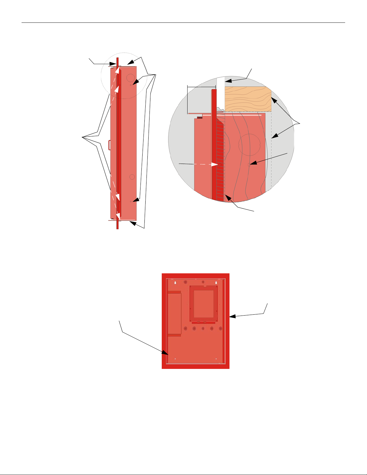
3.1.2 Flush Mounting
This Section describes how to flush-mount the cabinet into a wall. To recess mount the cabinet, you will need to have the
optional Trim Ring P/N VIP-TR (ordered separately).
To recess mount the cabinet, refer to the following these steps.
1. Remove the cabinet door and the dead front panel.
2. Cut a recess hole 20-1/4” W x 26-3/4” H (51.44 cm W x 67.95 cm H). There should be 1.5" to 1.75" (3.8cm to 4.45cm) of
cabinet space extending from the wall.
This space should be measured from either the top edge or bottom edge to the exterior side of the sheet rock. (See Figure
3.2).
3. To mount the cabinet to the wall studs, insert a screw through the cabinet’s side mounting holes into the wall stud.
Bottom Mounting Holes
20" (6.09m)
26-½”
Key Shaped Holes
8.05m
NOTE: Do not insert the cabinet deeper than recommended in Step 2. If the cabinet is mounted to deep, you will not be able
to re-attach the door assembly.
PRELIMINARY: TR-FFT Fire Fighter’s Telephone Manual — LS10309-001TR-E:A 04/28/2021 13
Mounting the Cabinet Installation
Figure 3.2 shows the trim ring locations and dimensions.
Figure 3.2 Detail of Flush Mounting with Trim Ring
4. Place the trim ring around the perimeter of the cabinet. See Figure 3.3.
.
Figure 3.3 Trim Ring Around cabinet
5. Use the self-tapping sheet metal screws to secure the trim ring from the inside of the cabinet.
6. Re-attach the cabinet door assembly.
Side View of Cabinet
Sheet Rock
Sheet Rock
Mounting
Studs
Cabinet
Mounting Hole
Trim Ring
Mounting
Hole
Cabinet
Mounting Hole
and Trim Ring
Trim Ring
Trim Ring
Mounting
Hole
1.5 to 1.75”
(3.8 to 4.4cm)
Trim Ring
Cabinet
14 PRELIMINARY: TR-FFT Fire Fighter’s Telephone Manual — LS10309-001TR-E:A 04/28/2021
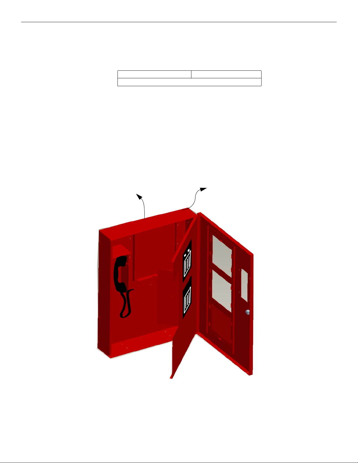
Installation Fire Fighter’s Handset Installation
Cabinet Door and Dead Front Removal
When you install the cabinet, it may be necessary to remove the cabinet door and the dead front panel. This Section provides
instructions on how to remove the cabinet door and the dead front panel.
1. Using a Phillips head screwdriver, remove the six screws that hold the dead front panel in place. See Figure 3.4.
.
Figure 3.4 Cabinet Door and Dead Front Panel Removal
2. Using a 1/4”(.64cm) hex drive, remove the six hex nuts that hold the cabinet door in place. See Figure 3.4.
Re-Attaching the Cabinet Door
To re-attach the cabinet door, refer to the procedure in Section3.
3.2 Fire Fighter’s Handset Installation
TR-FFT Local Handset installation involves the following steps:
1. Insert the phone cord through the hole of the dead front panel. See Figure 3.5.
Figure 3.5 Handset Cord Inserted Through the Dead Front Panel Hole
2. Attach the strain relief clip to the phone cord. The strain relief clip should have about 2 ¾” (6.99cm) length of phone cord
through it. See Figure 3.6.
3. Push the strain into the hole in the dead front panel.
Cabinet Door
Dead
Front Panel
Dead Front
Panel Screws
Cabinet Door
Hex Nuts
Cabinet Door and Dead Front Removal
When you install the cabinet, it may be necessary to remove the cabinet door and the dead front panel. This Section provides
instructions on how to remove the cabinet door and the dead front panel.
1. Using a Phillips head screwdriver, remove the six screws that hold the dead front panel in place. See Figure 3.4.
.
Figure 3.1 Cabinet Door and Dead Front Panel Removal
2. Using a 1/4”(.64cm) hex drive, remove the six hex nuts that hold the cabinet door in place. See Figure 3.4.
Re-Attaching the Cabinet Door
To re-attach the cabinet door, refer to the procedure in Section3.
Cabinet Door
Dead
Front Panel
Dead Front
Panel Screws
Cabinet Door
Hex Nuts

PRELIMINARY: TR-FFT Fire Fighter’s Telephone Manual — LS10309-001TR-E:A 04/28/2021 15
TR-24Z-EXT Installation Installation
.
Figure 3.6 Strain Relief Clip Installation
3.3 TR-24Z-EXT Installation
The TR-24Z-EXT expander board offers the option to add additional zones to the TR-FFT.
To install the TR-24Z-EXT, do the following steps.
1. Open the cabinet door and the dead front panel.
2. Remove the power. See Appendix A: for a list of the compatible powering devices.
3. Remove the blank plate and discard.
4. Mount the TR-24Z-EXT on the six mounting studs located on the inside of the dead front panel.
5. To secure the board, use the nuts removed from the blank plate. See Figure 3.7.
Figure 3.7 Mounting Locations for the TR-24Z-EXT
6. Connect one end of the wiring harness (P/N 130398 supplied) to the TR-FFT and connect the other end of the wire harness
to the TR-24Z-EXT as shown in Figure 3.8.
mounting studs
mounting studs

16 PRELIMINARY: TR-FFT Fire Fighter’s Telephone Manual — LS10309-001TR-E:A 04/28/2021
Installation TR-FFT Installation
Figure 3.8 Wire Harness Connection from TR-FFT to TR-24Z-EXT Zones 25- 48
7. Restore the power. See Section 3.5.
3.4 TR-FFT Installation
The TR-FFT installation involves the following steps:
• Connect any outputs that will power* the TR-FFT. (See Section 3.5).
• Set the DIP switch ID for the TR-FFT (See Section 3.6.1).
*See Appendix A: for compatible powering devices. For additional information, refer to the Manuals on the website www.tri-
gaglobal.com.
3.5 Power Operation
This Section provides instructions to install the appropriate DC power source.
1. Connect the TR-FFT to the appropriate DC power source. See Section 2.4.1 for power requirements. For compatible
product see Appendix A.
2. Use the on-board DIP switch to assign the configuration setting to the TR-FFT. (See Section 3.6.1).
3.6 DIP Switch Settings on TR-FFT
This Section describes how to configure the DIP switch setting on the TR-FFT.
1. Refer to Section 2.3 to identify the location of the DIP switches on the TR-FFT board.
2. Configure the TR-FFT module by adding it to the System using the JumpStart feature. See Section 6.3 for information on
the JumpStart Operation. Table 3.1 lists the possible DIP switch configurations.
3.6.1 DIP Switch
Figure 3.9 DIP Switch
TR-FFT
DIP Switch ON OFF
1 SLC Devices Installed SLC Devices not Installed
2 Trouble PZT Enabled Trouble PZT Disabled
3 SLC Class A Supervision SLC Class B Supervision
4 Phone Circuit Class A Supervision Phone Circuit Class B Supervision
5 First TR-24Z-EXT Expander Board Installed First TR-24Z-EXT Expander Board not Installed
Table 3.1 TR-FFT DIP Switch Configurations

PRELIMINARY: TR-FFT Fire Fighter’s Telephone Manual — LS10309-001TR-E:A 04/28/2021 17
TR-FFT Fire Fighter Telephone Module Connection Installation
3.7 TR-FFT Fire Fighter Telephone Module Connection
The TR-FFT provides the connection for a single Class B or Class A telephone audio circuit. See Section 4 and Section 5 for
examples of audio zone configurations. A monitor module can be used to monitor the connection of the Fire Fighter Telephone
remote handset (TR-RHS) into the TR-FPJ, which is then displayed on the TR-FFT active zone LED during the JumpStart fea-
ture.
Figure 3.10 Monitor Modules to TR-FFT Connections
3.8 TR-FPJ Installation
The TR-FPJ Firefighter Phone Jack mounts to any of the following:
• a single-gang electrical box (4" x 2-1/8" x 2-½") (10.16cm x 5.54cm x 6.35cm) or
• when the addressable mini-monitor module is installed with it, a deep single-gang electrical box (4" x 2-1/8” x 3-¾”)
(10.16cm x 5.54cm x 9.53cm).
Connect the telephone audio loop between the TR-FPJ and the TR-FFT as detailed in Figure 3.12.
All circuits are power-limited and supervised.
To TR-FFT to SLC Terminal
TB4 Connectors or other
monitor modules.
The wiring between the monitor module
and TR-FPJ is supervised by the monitor
module. A 47K ΩEnd-of-Line resistor is
built into the TR-FPJ.
To TR-FFT Phone TB4
phone In/Out + –
connections or other
TR-FPJ’s or TR-
STSR/STSS
TR-FPJ

18 PRELIMINARY: TR-FFT Fire Fighter’s Telephone Manual — LS10309-001TR-E:A 04/28/2021
Installation TR-STSR/TR-STSS Installation
Figure 3.11 TR-FPJ (Phone Jack) and TR-RHS (Handset)
Figure 3.12 TR-FFT-to-TR-FPJ Wiring Connection
3.9 TR-STSR/TR-STSS Installation
The Single Telephone Stations are packaged in a series of parts. The telephone chassis, backbox, break glass kit and door with
key lock are all ordered separately. Up to ten remote handsets may be operated simultaneously.
3.9.1 Assembly of Units with Coiled Cord Handsets
The following assembly steps are for telephones with coiled cord handsets. These steps must be accomplished once the enclo-
sure has been mounted and the system wiring is in place.
1. Attach the System wiring to the terminal strip on the telephone chassis assembly.
2. Insert the 6-32 nut in the backbox. Do not tighten the nuts.
3. Install the telephone chassis assembly in the backbox.
4. Install the trim ring on the backbox using the 6-32 wing nuts. Do not tighten.
5. Install the door assembly. To secure, tighten the wing nuts.
To TR-FFT to SLC Terminal TB4
Connectors or other TR-MINIMON
4.7KW, 1/2 watt ELR
(Install on the last device for
Class B telephone circuit only).
TR-FFT
TR-FPJ

PRELIMINARY: TR-FFT Fire Fighter’s Telephone Manual — LS10309-001TR-E:A 04/28/2021 19
TR-STSR/TR-STSS Installation Installation
.
Figure 3.13 TR-STS Telephone Connection
Figure 3.14 EOL Example
Contact EOL set to
Connected
*See Figure 3.14 for
EOL example
To:
TR-FFT Audio
or
TR-FPJ Audio
or
TR-STSS Audio Connect to the TR-FFT to SLC
Terminal TB4 connectors or
the other mini-monitors
Audio -
Audio +
20 PRELIMINARY: TR-FFT Fire Fighter’s Telephone Manual — LS10309-001TR-E:A 04/28/2021
Section 4: SLC Device Installation
4.1 List of SLC Devices
The following SLC devices can be used with the Fire Fighter’s Telephone. For more information, refer to the device installa-
tion instructions (packaged with the device).
4.2 Maximum Number of Devices
The TR-FFT supports up to 72 TR-MINIMON devices on one TR-FFT System.
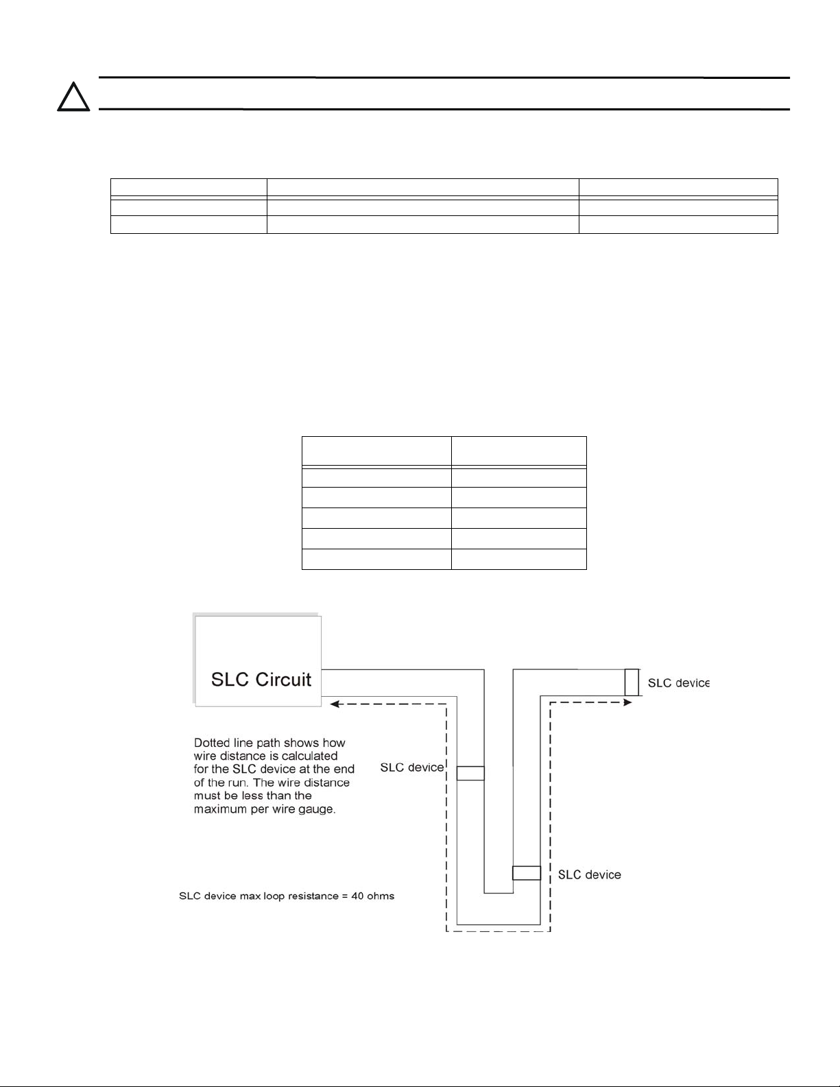
4.3 Wiring Requirements for SLC Device
The information in Section 4.3 and Section 4.4 pertains to the TR-MINIMON - Mini Monitor Module.
4.3.1 Wiring SLC Devices in (Class B) Configuration
There is no special wire required for the addressable loops. The wire can be untwisted, unshielded, solid or stranded as long as
it complies with the National Electric Code 760-51 Requirements for Power-Limited Fire Protective Signaling Cables. Wire
distances are computed using copper wire.
• The maximum wiring resistance is 40 ohms to the farthest SLC device.
• The maximum loop length depends on the wire gauge. See Table 4.2.
Figure 4.1 and Figure 4.2 show how the length is calculated when you use the Out and the Back Tap T-Tap style wiring.
.
Figure 4.1 Calculating the Wire Run Length for a Simple Out and Back
When you use the T-taps, the following are required:
• The total length of all taps and the main bus must not exceed 40,000 feet.
• Use the maximum distance requirements for the various wire gauges.
!
CAUTION: TO PREVENT THE RISK OF ELECTRICAL SHOCK AND DAMAGE TO THE UNIT, SHUT OFF THE POWER AT
THE CONTROL PANEL WHEN YOU INSTALL OR SERVICE THE CONTROL PANEL.
Device Part Number Model Name/Description Install Sheet Part Number
TR-MINIMON Mini Monitor Module I56-6978
TR-ISO Fault Isolator Module I56-6977
Table 4.1 SLC Devices
Wire Gauge Max. Distance
22 AWG 1200 feet
18 AWG 3100 feet
16 AWG 4900 feet
14 AWG 7900 feet
12 AWG 10,000 feet
Table 4.2 Wiring Gauge and Distance Chart
Table of contents
Other TRIGA Telephone manuals


