Trigano Jardin OSMOSE Oval User manual

Read carefully and keep+
for further consultation+
swimming pools
without support struts
OSMOSE
Assembly
instructions
TRIGANO JARDIN
Le Bo lay - 41170 CORMENON
Réf. 123714
Revision: 0
Oval
and
round

Important information
•NUMBER OF PERSONS REQUIRED FOR ASSEMB Y : 3 PEOPLE.
• ESTIMATED ASSEMB Y TIME NOT INC UDING GROUND PREPARATION : 2 DAYS.
• NUMBER OF PACKS IN THE KIT : 1.
A THE FI TERS COMP Y WITH THE INSTA ATION STANDARD C15 -100 SPECIFYING THAT ANY E ECTRICA APP IANCE SI-
TUATED WITHIN 3.50M OF THE POO AND FREE Y ACCESSIB E MUST HAVE A VERY OW 12V POWER SUPP Y. ANY 220V E EC-
TRICA APP IANCE MUST BE SITUATED AT EAST 3.50M FROM THE EDGE OF THE POO . CONSU T THE MANUFACTURER FOR
ANY MODIFICATION OF ANY OR SEVERA E EMENTS OF THE FI TERING SYSTEM.
THE EVE OF SAND IN THE SAND FI TER TANK MUST NOT EXCEED 2/3 OF THE HEIGHT OF THE TANK.
MANUFACTURER’S WARNING: WE ADVISE AGAINST DISMANT ING THE SWIMMING POO
For further explanations or in case of installation problems with the swimming pool kit, please contact us:
TRIGANO JARDIN
Le Bo lay
41170 CORMENON
Safety Recommendations
2
Tél : +33 (0)2 54 73 55 82
Fax : +33 (0)2 54 73 55 81
The safety of your children depends on you alone!
The Risk is greatest when children are younger than
5 years old. Accidents do not only happen to others!
Be ready to deal with it!
A reminder of some elementary safety rules:
• Surveillance of children must be close and constant.
• Designate one person responsible for safety.
• Increase surveillance when there are many users in the swimming
pool.
• Never leave a child alone near a swimming pool.
• Never leave a child who cannot swim unattended by adults.
• Never let a child swim alone.
• Make sure that people who do not know how to swim use floating
aids).
• Make sure that your child is wearing inflatable armbands or a ring
when near the pool.
• Teach your children to swim as soon as possible.
• Wet your neck, arms and legs before entering the water.
• Never enter the water suddenly, especially after a meal, after a long
period of sunbathing or after intensive physical effort.
• earn lifesaving reflexes, especially with regard to children.
• Prohibit diving and jumping.
• Prohibit running or boisterous games in and around the pool.
• Do not allow access to the pool without a lifejacket to children who
cannot swim and unaccompanied in the water.
• Do not walk on the lip.
• Do not climb or sit on the side wall.
• The ladder should be straight and placed on a solid base.
• You should always be facing the ladder when getting into or out of
the pool.
• Never use the ladder for any purpose besides that for which it was
designed, i.e. getting into or out of the pool. It was not built for jum-
ping and diving.
• Do not leave toys near or in the pool if it is not attended.
• Check from time to time that all parts of the pool are in good condi-
tion (for example: traces of rust on the bolts and screws).
• Tighten bolts and screws whenever possible.
• Never modify any parts, never remove any parts and never drill holes
in the pool.
• Ensure that the water is always clear and healthy.
• Never swim while the filtration system is operating.
• Follow the installation instructions closely and refer to the precau-
tions for safe use and storage indicated on the packaging of the
treatment products.
• Store water treatment products well out of the reach of children.
• Memorize and display emergency telephone numbers close to the
pool (all emergency services in the United Kingdom and Ireland can
be reached on telephone number 112).
Provide any equipment that may improve safety.
This equipment is an aid to safety. Under no circumstances
does it replace close supervision.
• Provide a secure, protective perimeter barrier with the gates conti-
nuously closed (for example a hedge cannot be considered to be a
barrier).
• Manual or automatic protective cover, correctly installed and atta-
ched.
• Electronic detector of movement or fall, working and operational, al-
though this in no circumstances replaces close supervision.
• Telephone available close to the pool so as not to leave your children
unattended when you are telephoning.
• Ring and pole next to the pool.
In the case of an accident:
• Remove the child from the water as quickly as possible.
• Immediately call help and follow the advice you are given.
• Replace wet clothes with warm blankets

Preamble
Important: diving and jumping into swimming pools is prohibited
Dear client,
Congratulations, ou have bought a swimming pool of superior qualit and
durabilit .
We suggest that ou read the instructions closel to get to know the different
parts of our swimming pool.
Make sure ou understand all the stages before starting assembl .
Installation that does not compl with the enclosed instructions could cause
damage to our pool and cancel the guarantee.
We hope ou have a pleasant and refreshing summer.
For good results you should read this document before you start the installation of your pool and
consult it stage by stage according to the progress of your installation.
Keep this notice for further consultation.
NB: TRIGANO JARDIN cannot be held responsible for incorrect installation or incorrect operation due to the non respect
of the specifications or the instructions for assembly and use and declines all forms of responsibility in this regard.
1- SOME REGULATIO S
Before beginning the installation of your pool and electrical equipment you must find out from your local town hall
about local and municipal regulations.
If you are a tenant, make sure you have informed your landlord about this installation.
Make sure you follow safety standards with respect to barriers and swimming pool covers. Choose an appropriate site for
your swimming pool by considering the following points:
• The distance between the swimming pool and the barrier.
• Nearby trees (roots, falling leaves, etc.).
• Any overhead cable or washing lines.
• The presence of underground cables and gas piping.
• Do not install the swimming pool on a concrete surface in case of freezing, or on tarmac, wood, peat, lawn, course
gravel or any other terrain that has been treated with chemical products.
• The position of accessories (e.g. filtration systems).
• Appropriate electrical outlets.
• The direction of sunlight in your garden.
• Do not install the swimming pool during strong winds
Having and using this swimming pool may not carry any extra insurance cost. However, in order to follow regula-
tions with respect to any risk of water damage or Civil Responsibility we advise you to declare your swimming pool
to your insurance company.
WAR I G : NEVER EAVE AN ABOVE-GROUND SWIMMING POO WITHOUT WATER.
3

4- TOOLS REQUIRED FOR ASSEMBLY
• Tape measure • Spirit level • Felt pen
• String • Rake • Clothes pegs
• Woodsaw • Straight plank • Shovel
• Stake • 5cm adhesive tape • Nails
• Pliers • Screwdriver (flat or square) • Knife
• Monkey wrench • Plumb bob • Adjustable spanner
• Stanley knife • 40cm x 40cm plank • Bags of fine sand (in large quantities)
• 12V electric screwdriver (advised)
4
Chow do I get organised to assemble
my swimming pool?
Installation planning :
• Time required for installation: 4 days, including 2 days to prepare the ground and 2 days to assemble the pool.
• Number of people required for assembly : 3.
READ THESE I STRUCTIO S CAREFULLY A D KEEP THEM FOR FURTHER CO SULTATIO .
BE CAREFUL A D VIGILA T.
1- CHOOSI G A D LEVELLI G THE I STALLATIO SITE
• Your pool is intended exclusively to be placed on the ground.
• Your pool must be installed on firm and solid ground.
• The entire surface of the swimming pool must be levelled. Sloping surfaces must be levelled by lowering the
higher ground. DO NOT ADD EARTH to bring the lower parts up to level – you need to ensure perfect support for
the weight of the pool.
• The area chosen must be cleared of grass, rocks and stones, roots and other objects that risk piercing the liner.
Just setting the pool on a patch of grass could cause rotting, resulting in foul odours.
• Do not set the pool on a surface that has been treated with insecticides or other chemical products, as this could
damage the liner (e.g. stains, colour loss, etc.).
2- PREPARE YOURSELF I ADVA CE
• Will you build a boundary around the swimming pool later? If so, make sure you leave enough space around the
pool area.
• Do you use pool accessories or other articles that run on electricity? If so, position your pool near electrical power
sources or plan to have them installed later by an electrician.
• You are strongly recommended to use a ground sheet under the liner in order to preserve its lifetime.
3- I STALLATIO PERIOD
The choice of installation period is important...
• Do not assemble the pool during strong winds.
• Ideal outdoor temperature: 15°C or higher.
• If you install it in warm weather conditions (between 25 and 35°C), you should install the liner in the evening.
5
Dimensions of OSMOSES
574,04 cm
608,60 cm 365,76
cm
518,16
cm
3.65 x 6.10 (12 x 20)
788,67 cm
727,71 cm 365,76
cm
518,16
cm
3.65 x 7.31 (12 x 24)
975,36 cm
914,40 cm 462.28
cm
619,76
cm
4.57 x 9.14 (15 x 30)
1066,80 cm
1005,84 cm
711,20
cm
5.48 x 10.05 (18 x 33)
Real Size of the Swimming Pool Area required for Installation
290 cm
240 cm
410 cm
360 cm
510 cm
460 cm
600 cm
550 cm
Ronde 2,40 m (8’)
Ronde 3,60 m (12’)
Ronde 4,60 m (15’)
Ronde 5,50 m (18’)
2.40m (8’) Round
3.60m (12’) Round
5.50m (18’) Round
4.60m (15’) Round
Do not worry that you have not used all of the holes in the lower corner-pieces.
This same corner-piece is used on different models and there are holes that are not used on this swimming pool model.
aving decided on the area for installation, make sure you have enough space around it and prepared the ground for cleaning, you can
start levelling the ground. The ideal tool to do this is an aluminium mason’s ruler. If you haven’t got one, use a long plank (the plank should
be completely straight) and a spirit level as shown in the illustration.
The best way to level the ground for an above-ground swimming pool is to start at the lowest spot and to lower the level of the rest by digging.
It is not advised to raise the lowest areas so that they are the same level as the higher areas because the ground will still settle after your
swimming pool has been filled. This could destroy your pool, which would be dangerous and would not be covered by the guarantee.
You probably won’t be able to render the ground completely flat before placing the structure on it, but you will make later work a lot easier
by trying to get the most done now. We advise you not to proceed with the next stages before your ground is level to within 2.50cm.
6
STAGE 1 - Levelling: oval and round pools
DO NOT ADD FILLER OR EARTH TO THE LOWER AREAS
Remove earth and grass Remove grass only
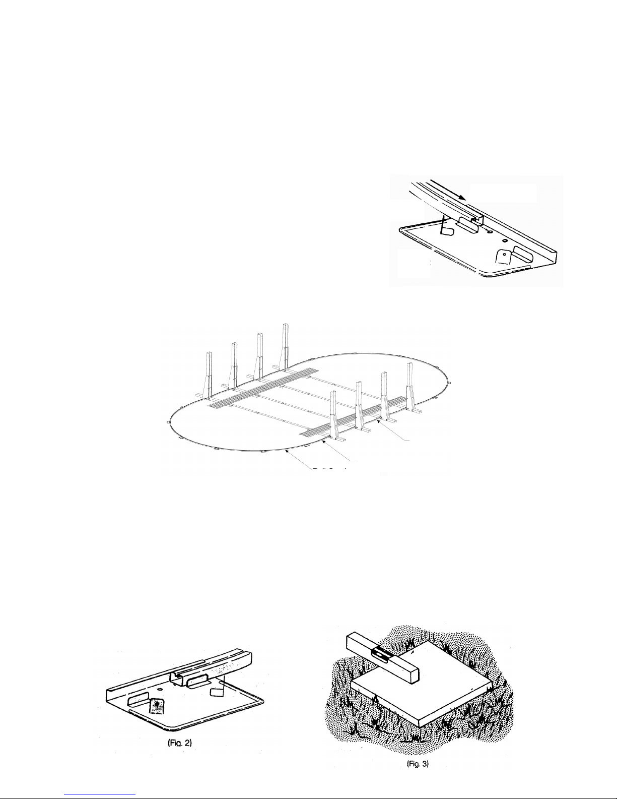
STAGE 2 - Pre-assembly of straight sides of an
oval pool. (For round pools, go to STAGE 6)
A) Begin by putting the tensile strip supports in place (15) in such a way that the open sides of each support are facing upward. Then slide
the corner-piece (5) over the supports so that they form a tube. Make sure that the holes of the two corner-pieces are aligned, but don’t
bolt them together yet.
B) Now slide the oval risers (4) over the lower corner-pieces while checking that the holes are aligned as shown in the illustration.
C) Once the oval risers are attached, fix a left-side boot (13) and a right-side one (14) to each. The parts are marked “L” (left) and “R” (right).
The boots are fixed onto the corner-pieces and around the oval riser. Once they are in place, screw the left and right boots together
using the three screws (8).
D) All the holes should be aligned at this stage. Tighten the parts together with the bolts as indicated in the illustration.
Use the bolts (12) and nuts for the corner-pieces and the stainless steel bolts to connect the boots to the risers.
Remember to add the three-hole plates (16) in front of the boots.
E) Once all the (12) bolts have been tightened, install the lower straight side extensions. We do this by placing the extension onto the cor-
ner-piece just inside the oval riser. The hole in the extension should be aligned with the hole in the lower corner-piece.
Connect the extension to the corner-piece with a single screw (9) for each, as indicated in the illustration.
1. Pressure plate
2. Right lower side rail
3. Oval upper plate
4. U-shaped oval riser, length 1317mm
5. Corner-piece, length 1330mm
6. Lower straight side extension
7
STAGE 3 – Assembling the tensile strips of an oval
swimming pool.
When you take out the tensile strip parts, you will notice that there are two different lengths. Each complete strip is composed either of
two parts for pools 365cm wide, or of three parts for pools over 365cm wide. Whatever the size of your oval pool, there is always a strip
material part that is 99.75cm long for each tensile strip assembly.
(Example: a 15x30 pool consists of four strip assemblies, so it is delivered with four 39.275" (99.75cm)-long parts). For the Osmose sys-
tem, we WILL NOT USE this part. You should put these parts aside so you do not include them accidentally in your tensile strip assem-
bly. We only use them for the assembly of a standard oval pool.
Connect the remaining parts of each strip to one another with two bolts (10) on each end. When they are completely assembled (as shown
in the illustration), connect the end of each strip to a lower corner-piece, with two (10) bolts on each connection. Please don’t forget that
the strips must be connected to the lower side of the corner-pieces, with the heads of the bolts at the top and the nuts at the bottom. Al-
ways use the two holes closest to the ends of the corner-pieces when you connect the strip sections to the corner-pieces.
3.65 x 6.10 3.65 x 7.31 4.57 x 9.14 5.48 x 10.05
103.33cm 12
104.20cm 4 6
133.82cm 12
ABC DE
5
15
4
14
13
11
12
8
16
11
9
6
7. Tensile strip
8. Metal screw 4.8x12
9. Metal screw 5.5x20
10. Bolts 8x12
11. Bolts 48x115
12. Bolts 48x125
13. Left-side boot (without support)
14. Right-side boot (without support)
15. Tensile strip support, length 1155mm
16. Three-hole plate.
Tensile strip section
103.33 cm 103.33 cm
103.33 cm
(10)
Nuts
457 cm
(7)
Example of assembly for a swimming pool of 4.57cm x 9.14cm
STAGE 5 - Installation of the pressure plates :
oval swimming pool.
Place a pressure plate (1) from 111.76cm on each lower corner-piece in such a way that the centre of the plate is level with the centre of
the corner-piece. When we install these plates, the corrugated side should be facing upwards and the flat side facing the ground. One of
the edges has a larger smooth area than the other one. The wider edge should be closest to the centre of the pool. The pressure plate
should pass the end of the corner-piece by about 2.50cm. If this has been done correctly, the two holes at the centre of the pressure plate
should be aligned with the two holes of the centre of the corner-piece. Connect the plates to the corner-pieces with two screws (9) for each.
Once all the plates are attached to the corner-pieces, the plates should overlap each other. Connect the plates to one another with screws
(9) for each overlapping section.
8
STAGE 4 – Installing the straight sides :
oval swimming pool.
Once you have completely finished the assembly of the tensile strips and attached them to the lower corner-pieces, you can begin to ins-
tall them in their final positions. If your pool has an odd number of strips, (e.g. a three-strip pool measuring 3.65 x 7.31), find the centre of
the area that you levelled earlier, place the first strip there and assemble the oval riser as shown in the illustration.
Now you place a 106-cm assembly from the centre of one corner-piece to the centre of another corner-piece, on either side of this first
assembly.
Continue in the same way until all the assemblies have been used.
If your pool has an even number of strips (e.g. a pool of 15 x 30, which has four), find the centre point and mark it on the ground, and place
an assembly on either side of this mark, 53cm from the centre of the corner-pieces. If your pool has more than two assemblies, you will
place the next assemblies at a distance of 106cm from the centre of the previous one, keeping an equal number of assemblies on either
side of the centre point.
Once all the assemblies are in place, you must make sure that all the oval risers on the same side are aligned. This can be done visually
fairly accurately, but we would advise you to use a length of taut string between the first riser and the last one. If there are risers that do
not touch the string or that pass it, adjust the assembly until the string is perfectly straight
If you are trying to install your pool parallel with an existing object such as a fence, you only need to measure the distance between this
and each oval riser to make sure that each distance is the same.
Once you are sure that one side is straight, the other side should already be straight. If this does not seem to be the case, check that the
strips are flat on the ground.
(1)
9
STAGE 6 – Assembly of lower rails :
oval and round swimming pools.
Once you have unpacked the lower rails, you will certainly have noticed that there are three different sizes of rails (except for the pool size
3.65 x 5.18 which only has two sizes). Some rails measure 95.25cm, others measure 99.06cm and the others are longer, but the exact
length depends on the size of your pool.
It is very important that the rails are now separated according to size.
1/ OVAL :
A) The lower white rails, measuring 95.25cm, go between the oval risers.
They simply need to be pushed into the lower right-side extension on either side.
These rails should rest flat on the ground, but you can check this when you level the
swimming pool
B) The four lower 99.06cm white rails are for the “angles”. One side hooks in to the
right-side extension on the last oval riser, while the other side slides into a lower
plate as shown in the diagram.
C) You should have an even number of the longest lower rails, and also an even num-
ber of lower plates. These form the curved parts of your pool. alf of these rails and
plates go on one side and the other half go on the other side. Slide each rail into the
plate, as shown. Make sure that the plate is outside the half-circle formed on either
side of the pool. Once the rails are assembled, you should see the complete shape
of your oval swimming pool on the ground.
2/ ROUND : T ERE IS ONLY ONE TYPE OF LOWER RAIL
Form a circle around the circumference with the curved lower rails. Connect the rails with the lower plates. You must insert the rails into
the lower plates as far as the stopper (see figure 2). Check that the circle is round by measuring in three or more places. As the rails do
not automatically form a true circle automatically, do not skip this step, otherwise you will end up with a slightly oval shape, which could
cause you problems. You can squeeze the rails between your thumb and index finger to insert them easily into the lower plates.
Once you have connected all the lower plates, centre the frame with the lower plates on the 5X20X40 patio stones.
THERE SHOULD NOT BE ANY SPACE BETWEEN THE GROUND AND THE BOTTOM OF THE RAILS. ALL THE PATIO STONES
SHOULD BE LEVEL WITH THE GROUND, SOLID, AND LEVEL WITH ONE ANOTHER IN ALL DIRECTIONS.
(See figure 3).
Spirit level
Patio stone
bottom
rail
slide bottom rail
up to bump
bottom
plate
curved rail
corner bottom rail
straight bottom rail
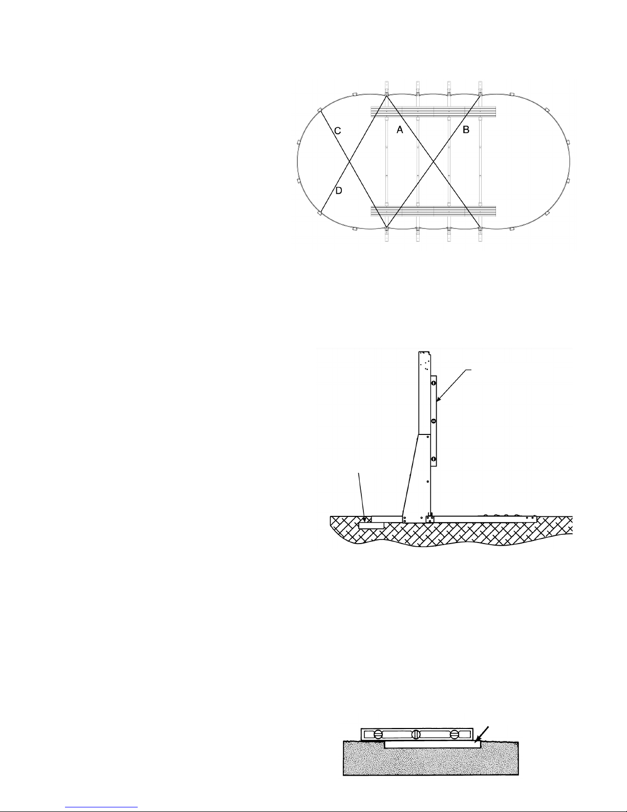
Levelling the straight sides is a crucial step for correct installation. If
this is not done precisely, you run a risk of encountering serious pro-
blems.
The lower corner-pieces are 5.08cm deep. The upper part of the
corner-piece must be level with the ground.
We advise you to dig into the ground to install the lower corner-
pieces one by one. Once all the corner-pieces on one side are at the
same level, place a 5x20x40 paving stone under the end of the cor-
ner-piece as shown. This must be done for each corner-piece. Re-
member that the stone is 5 cm thick and the corner-piece too. You
will have to dig down 10 cm in total for the corner-piece to be level
with the ground.
Once you have finished one complete side, do the same for each
lower corner-piece on the opposite side. When this is done, you
should check that all the oval risers are at the same level, with the
spirit level. The pressure plates and the straight lower side rails en-
sure that the lower parts are always 106.68cm from the centre.
Make sure that the tops of the oval risers are also.
STAGE 8 – Levelling the straight sides :
oval swimming pool.
STAGE 9 – Levelling the curved sides :
oval and round swimming pool.
The next stage is to level the curved sides of the pool. Before doing this, you may want to mesure the length and width of the whole pool
to make sure that the measurements are the same as those indicated on page 5 of this booklet. If there are a few centimetres difference,
your wall will not be correctly adjusted. You can repair this by sliding the lower curved side rails outside of the lower plates as shown. This
should be done in the same way for each plate.
Once you are sure that the pool is the right shape and size, level the curved sides of the pool. Do this by placing a 5x20x40 stone under
the end of each of the lower plates. The blocs should be set into the ground so that the lower plates are at the same level as the top of
the lower corner-pieces. It is also important to check that the rails between the plates are resting flat on the ground.
Note: Check the level in all directions.
When the paving stones are placed under the lower curved side
plates, leave 2.5cm of the stone on the inside of the pool and 10cm
visible outside the pool.
10
STAGE 7 – Straight-sides frame :
oval swimming pool.
Now that the base of the pool is completely assembled, you
must make sure that the straight sides of the pool are per-
fectly aligned.
We call this “framing the pool”.
We do this by measuring from the outside of the first oval riser
on one side to the outside of the last oval riser on the oppo-
site side (these are the two oval risers the furthest apart from
one another).
These measurements should always be taken from the bot-
tom of the riser, about 30cm from the ground, because, as
you go up, the measurements become less precise. Once you
have this measurement, you must proceed in the same way
with the two other opposing risers as shown in the diagram.
The two measurements should be identical.
If this is not the case, adjust one complete side until the mea-
surements are the same.
This step is very important; do not continue until the measu-
rements are identical. A must be equal to B and C must be equal to D
Spirit level
Concrete block
Ground level
LEVEL PAVING STONE
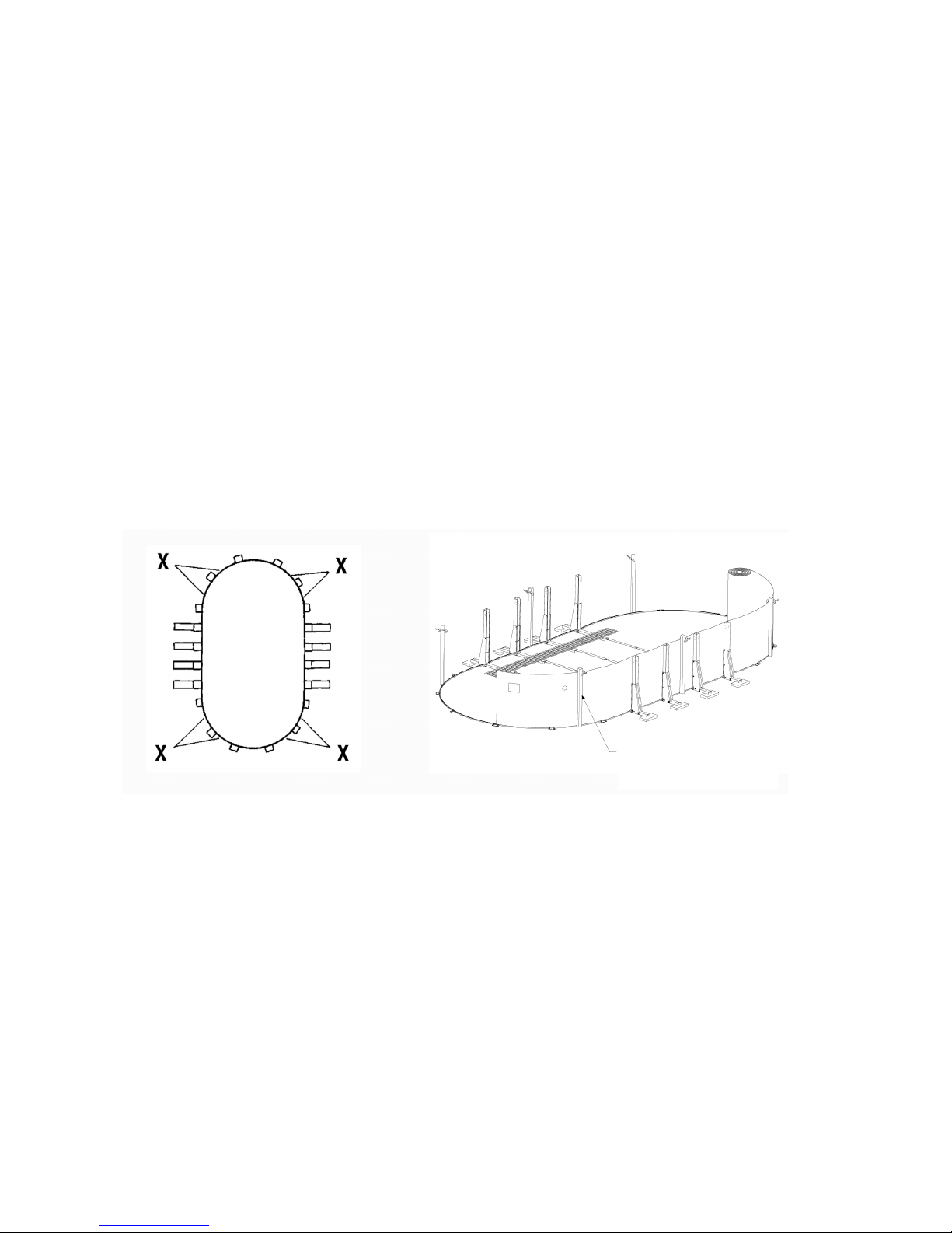
DO NOT ATTEMPT THIS STAGE IN WINDY WEATHER CONDITIONS. THE WALL IS VERY HEAVY
AND IT CAN BE EXTREMELY DIFFICULT TO HANDLE IN THE WIND. IF THE WIND CATCHES THE
WALL DURING INSTALLATION IT MAY CREATE A DANGEROUS SITUATION OR CAUSE DAMAGE
TO THE POOL.
1/ OVAL :
Before beginning the installation of the wall, you can remove one lower rail in order to move sand or fine earth for the protective angle and
the base of the pool, as long as the positions of the curved sides are marked with stakes (don’t forget to put the lower rail back in place).
During this stage you will use the box of the wall as a base to unroll the pool wall. While holding the joints of the wall behind a riser, be-
ginning with the wall at the middle of a lower plate, we suggest to place the skimmer and overflow hole at one of the four corners of the
rounded section of the pool. The position of the skimmer is determined by the place where you begin the wall.
In any case, the joints of the wall must be at one of the curved ends of the pool and not at one of the straight sides. Unroll the wall little
by little, inserting it into the lower rails. Do not unroll the whole wall at once, as this will make installation more difficult.
While you unroll the wall, you can install temporary inner stabilising rails, or use sticks with pegs to hold the wall in place vertically. This
will make assembly easier.
We also suggest for the rails and sticks that you use strips of adhesive tape from the wall to the straight side risers for more support du-
ring assembly.
If the side wall seems to be too long or too short, lengthen it or shorten the curved sides by sliding the lower rails equally into the lower
plates. If the ground is not straight, the wall can escape from the groove in the lower rails. Correct this if necessary by checking the level.
STAGE 10 - Installation of the walls :
oval and round swimming pool.
11
X = recommended skimmer position.
2/ ROUND:
Place the sheet and the wall inside the pool at one end. The end that should be at the top is indicated with a label. Beginning between the
two lower plates, insert the metal side wall into the groove of the lower rails. As the wall has a slot designed to fit an embedded skimmer,
make sure that the right end is at the top.
Although the slot may not be seen, the end that should be at the top is indicated with a label. If, after unrolling the wall, any of the holes
are obstructed by a riser, slide the wall to get enough slack.
If you do not wish to use the embedded skimmer, tape over the slot. To help you support the wall during this work, you can install tempo-
rary stabilising rails inside (see installation of inner stabilising rails). For better support, you can also install the risers temporarily, the
upper plates and the upper rails by fitting them around the pool as needed. If you install the upper rails temporarily, use only two screws
without tightening them (se the installation of the riser and the upper plate).
If the wall seems to be too long or too short, shorten it or lengthen the lower part by pushing the lower rails further in or pulling them out
from the lower plate. If the ground is not level, the wall can escape from its groove. If this happens, you must replace it.
IT IS IMPORTANT THAT THIS JOB IS DONE CORRECTLY!
While attaching the side wall, make sure that the aluminium strips that have already been attached do not touch each other. One bar
should be inside the pool (the head of the bold will touch the bar), the other bar should be outside the pool (the nut will touch the bar). In-
sert the bolts from the inside towards the outside so that the nuts are positioned at the outside of the pool. Do not tighten before all the
bolts and nuts have been inserted. While holding the bolt with a screwdriver, be careful that the screwdriver doesn’t slip and scratch the
head. If this happens, file down the scratch so that it does not cut the sheeting. We advise you strongly to cover the screw heads on the
wall with adhesive tape or something similar. It is possible that inserting the side wall into the lower rail can be difficult at the junction of
the 2 ends. You just need to insert a screwdriver into the groove and turn it to make space.
Use sticks to hold the wall

Using fine neutral alkaline earth or fine sand with no stones,
spread a base layer of 5cm over the entire surface area of your
swimming pool area in order to protect the liner. Check that the
tensile strips and the pressure plates are completely covered. If
the base does not completely cover the metal parts, they may da-
mage the liner. If you use a base layer of vermiculite, you should
have at least 5.08cm of earth or sand on the tensile strips and
pressure plates. Vermiculite alone will not be enough to cover the
metal parts and the liner could be damaged as a result.
In no case should you use products containing a large amount of
alkaline or acid such as peat sods.
This will cause corrosion of the pool
This angle will prevent the liner from creeping under the wall and
will also protect all the metal parts of the pool structure.
THIS IS NOT AN OPTIONAL STAGE
IT MUST BE FOLLOWED!
As earth contains chemical products and can cause colour fading or corrosion, we advise you to place sheets of plastic below the angle
around the edge of the wall so that the earth does not come into contact with the metal.
The manufacturer cannot be held responsible in the case of any presence of chemical products, and when any damage incurred. This will
not be covered by the guarantee. The plastic sheet will not stop any leakage if your liner is damaged. The plastic sheet is only designed
to protect the metal from corrosion.
IMPORTANT : This operation must be carried out with care! While joining up the wall, make sure that the pre-attached aluminium
edges are not touching one another. One bar should be inside the pool (the bolts will be touching the bar) and one bar should be outside
the pool (the nuts should be touching the bar). Insert the bolts with their heads on the inside of the pool. Do not tighten until all the bolts
are in place.
If your screwdriver slips and scratches the head of the bolt, file this down so that is smooth and will not tear a hole in the liner. We advise
covering the bolt heads inside the wall with three layers of insulating tape. If insertion into the lower rails seems tight at the place where
the wall joins up, insert a screwdriver and turn to create enough space, while being careful not to scratch the wall or the rails.
STAGE 11 – Assembly of the wall joints :
oval and round swimming pools.
REMINDER: ALL THE HOLES OF THE 52” (132CM) POOL MUST BE USED! 48'' (122CM) POOLS CAN HAVE UNUSED HOLES.
ALL THE NUTS SHOULD BE TIGHTENED BY HAND AS MUCH AS POSSIBLE. BARS SHOULD NOT TOUCH ONE ANOTHER.
IF THIS IS NOT DONE CORRECTLY THE POOL WILL BREA !
Type #1 Single Row Type #2 Attachment With Alternating View from Above
Bolts, View from Above
12
STAGE 12 - Preparation of the pressure angle :
oval and round swimming pools.
Side wall
Protective
angle
Plastic
sheet
Pre-attached
inner bar
Wall
Inside of
the pool
Inside of
the pool
Pre-attached
outer bar
Nut outside
the pool
Inside of
the pool Outside of
the pool
Wall
Nut on the
outside of
the pool
Inner bar of the wall
Outer bar
of the wall
Inside of the pool
Outside of the pool
Wall
Nuts
6x20
Screws
Wall bar
In most models, the top can be identified either by the presence of an extra
hole in the centre or by one on either side (according to the model) for the de-
corative hoods. Place the top plate on the riser, checking that the holes are
aligned and that the hooked part is facing the open side. Now screw the cen-
tral hole only, with the screw (8).
Do not do the holes on the sides for the moment. This will make thins easier
for the next step.
Install the risers with curved ends as shown in the diagram.
The top plates can remain unattached for the moment, but should be hooked
to the wall to stop them from falling. Check the curve of the end of the pool,
and that the poles have not moved, so that the pool has an oval shape. Place
the risers on the feet of the lower plates and affix them with number ten
screws. Check that the holes are perfectly aligned because the position of
the holes varies in most pools.
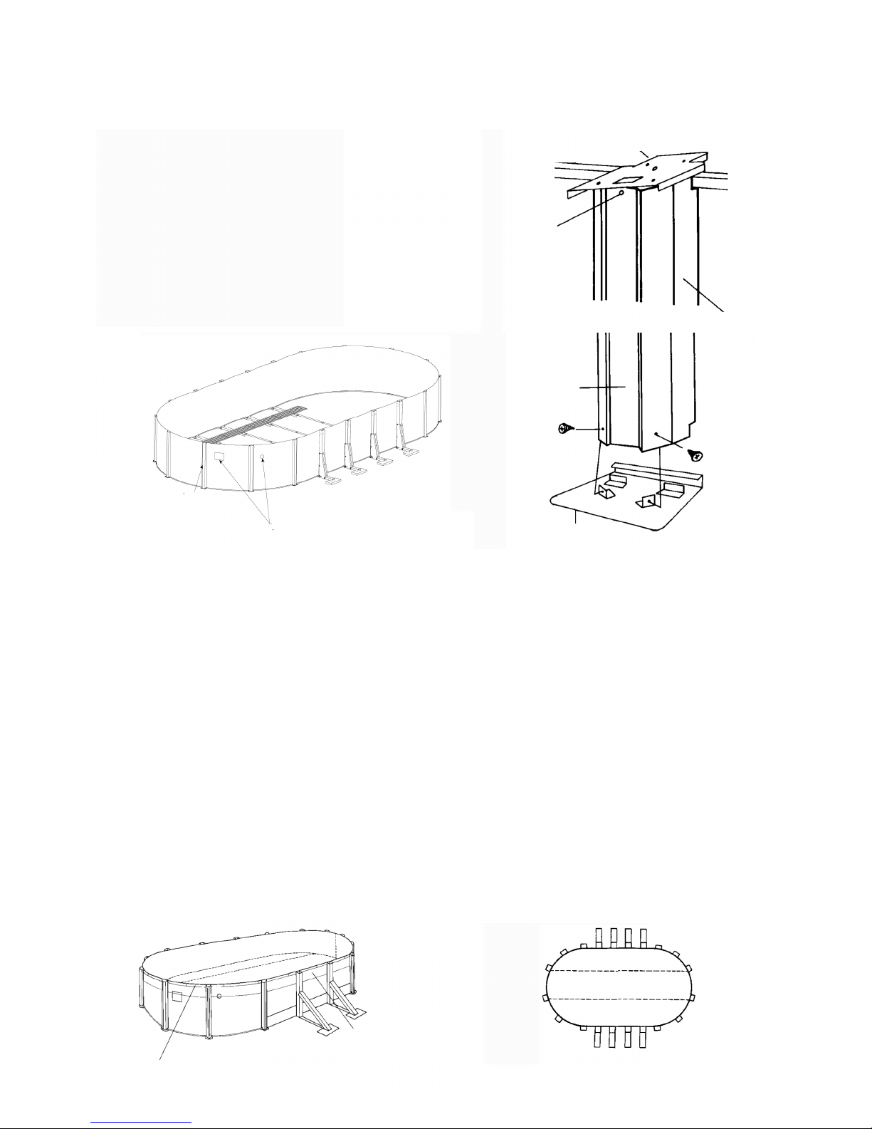
STAGE 13 – Assembly of curved risers :
oval and round swimming pools.
13
STAGE 14 - Preparation of the liner :
oval and round swimming pools.
Once the protective angle and the base are in place, pack down and rake the entire area of the pool. Check that there is no sand left on
the wall above the protective angle. This could cause pinholes in the liner. Before installing the liner, check that all the perforations for the
skimmer and the overflow are correctly set.
Screw (8)
Beginning with the liner wall seam, hang the liner on the wall, checking that the seam is straight and vertical, and perpendicular to the
ground. The edge should be regular. If you have a line with border decoration, just choose a mark and follow it around the pool. As you
pass the liner over the wall, you can attach it with plastic holding pegs.
STAGE 15 - Installation of the liner and the liner
holding joints :
oval and round swimming pools.
Liner falling onto the
wall of the pool
Plastic holding peg installed to
hold the liner in place. Make sure that the seams of the liner are parallel
with the wall, so that the liner is straight.
Insert the front
top plate screw
Screw (8)
Top plate
Lower plate
Riser
Riser
Risers
(wall joints hidden
behind the riser) NB: position of the skimmer
and the overflow

NB: Align the seam of the wall straight from top to bottom, far from the skimmer and the overflow.
14
CORRECT LINER SEAM
resting evenly on the
protective angle
of the pool
INCORRECT LINER SEAM
shifting on the wall.
This should not happen.
Correct the situation if
necessary.
STAGE 16 - Adjustment of the liner and assembly
of the skimmer :
oval and round swimming pools.
Once the liner is firmly and evenly held in place by
the holding pegs, pull the loos parts at the bottom
temporarily and evenly towards the wall, so that
loose areas are within the protective angle. When the
liner is correctly positioned, there should be no air
pockets between the liner and the ground or the wall.
Remove the pockets within the angle by adjusting
the liner overhanging the top of the wall.
Do not over-tighten; it should hang freely on the
sides. When a liner is correctly installed, there is no
pressure on the lower part of the liner, and the vinyl
of the walls is not stretched.
Start filling the pool.
When there is 1cm of water, spread the bottom of the
liner and remove any folds by hand, from the centre
of the pool towards the edge, until they have all been
removed. Do not cut the holes for the skimmer and
the overflow until the liner has been completely ad-
justed and the pool has been filled to 5cm maximum
beneath the overflow pipe hole.
CORRECT
No air spaces between the
liner and the pool.
The liner should hang freely
on the sides.
INCORRECT
Do not leave spaces between
the liner and the angle.
This will cause downward
pressure.
Correct this if necessary.
Cutting the liner for the overflow pipe
• By pressing lightly on the liner with your finger, find the position of the overflow opening.
• At this position, cut a circle centred only on the prepared cut on the wall and 2cm smaller than this prepared cut (figure 1).
• To do this, you can also make a cross with a Stanley knife, then cut the angles (figure 2).
Figure 1 Figure 2
Protective angle
Protective angle
Pool wall
wall
liner liner
cutting cutting
wall
15
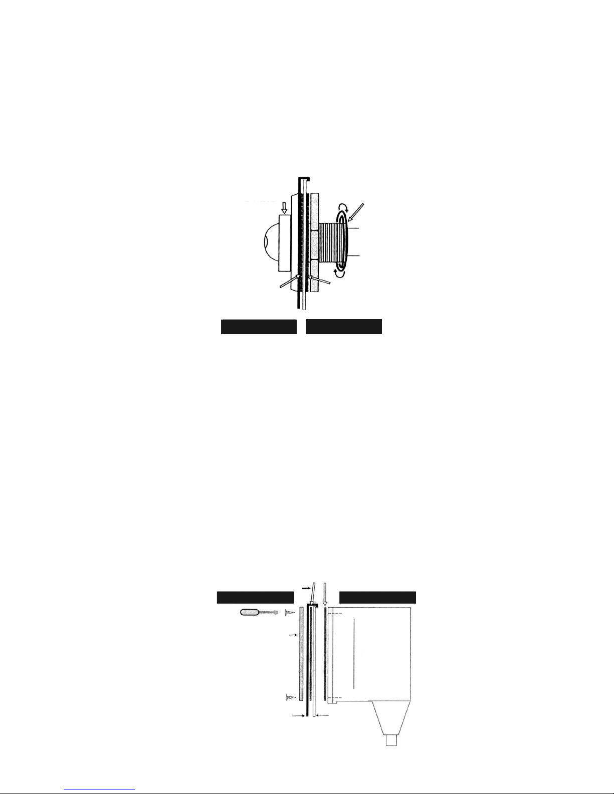
Installing the skimmer and the overflow pipe
1- INSTALLING THE OVERFLOW PIPE
• Unscrew the ring completely and remove the two circular joints.
• Insert the overflow piece on the inside of the wall, through the opening that you have made in the liner, then, into the first joint and the
pre-cut hole through the wall. The threaded part now shows on the outside of the pool.
• Put the last joint on and press the unit against the wall.
• Screw the ring on and tighten well.
• Check the assembly in this order: the liner, the first joint, the wall and the second joint sandwiched between the wall and the ring
(figure 3).
• Continue to connect the filter piping.
Figure 3
2 – INSTALLING THE S IMMER
The skimmer is pre-assembled; you have no gluing to do. Before putting it in place, you should check the following:
• Is the liner correctly centred?
• ave all folds been eliminated?
If so, you can install the seal.
VERY IMPORTANT: You should only cut the liner AFTER complete installation of the skimmer
• By pressing lightly on the liner with your index finger, find the position of the holes for the screws to tighten the seal.
• Using a nail, pierce the liner at the position where the holes match the four angles of the seal.
• Position in the following order: the seal, the liner and one joint against the inside of the wall, and the four screws of the seal.
• Place the other seal and the skimmer on the outside of the wall, in such a way as to sandwich: the seal, the liner, one joint, the wall,
the other joint and the body of the skimmer (figure 4).
• Install all the screws and tighten them well but not excessively, with a screwdriver: DO NOT USE AN ELECTRIC SCREWDRIVER.
• The joint is now sealed. Carefully cut the liner with a Stanley knife, around the inner edge of the seal.
Figure 4
Skimmer
INSIDE OF POOL OUTSIDE OF POOL
Joints
This joint is placed inside the
outer hole in
Wall
Seal
Liner
Wall
Liner
INSIDE OF POOL OUTSIDE OF POOL
2nd joint
1st joint
Overflow piece Ring
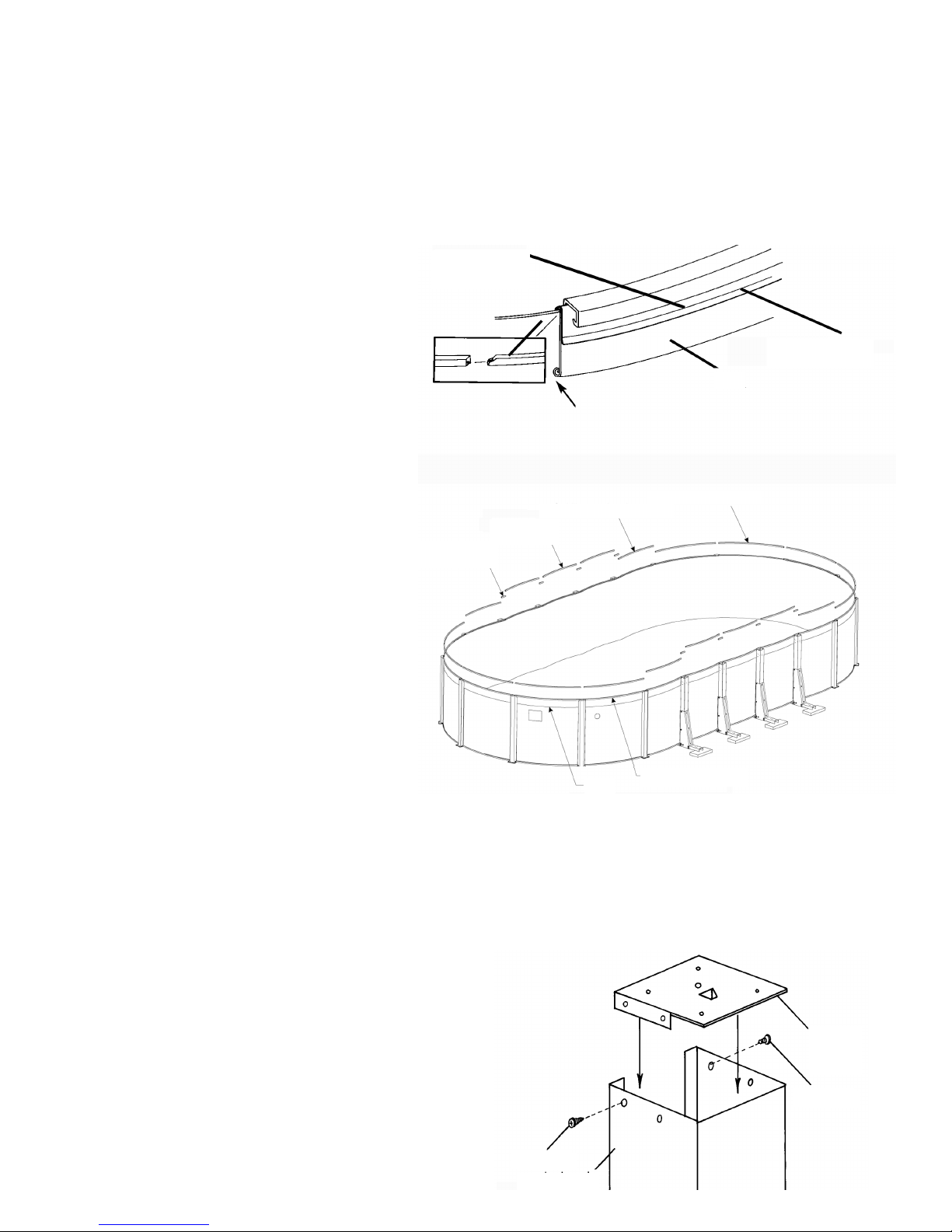
1/ OVAL :
Once the liner has been completely adjusted and the plastic holding pegs have been attached, the next stage is to attach the inner sta-
biliser rails. You should have rails of four different lengths (except for pool sizes 365.76cm x 518.16cm, which only have three). You should
have rails of 20.32cm, 83,82cm, four rails of 93.98cm and an even number of longer rails that have one bevelled edge and one straight
cut edge. Now separate the stabilisers according to size.
A) Beginning with the first riser of one of the curved
sides, fit the stabiliser rails over the holding pegs so
that they remain firmly in place. Leave the straight-
cut edge slightly raised so that the next rail can fit into
it easily, as shown in the diagram.
As you advance with the installation around the cur-
ved section, you will notice that the pointed part fits
easily into the straight end of the previous stabiliser.
It should fit in by a length of about 2.50cm.
This allows you to make adjustments by moving the
rails in or out.
Do this until you reach the last riser of the curved sec-
tion then continue in the same way for the “long” sta-
bilisers on the other curved section
B) Once the curved sections have been completed, find
the four 93.98cm stabilisers. Fit these over the hol-
ding joints in the “corners” in the same way, except
that they do not fit into the other rails. Remember, the
“corners” are the spaces between the last oval riser
and the first riser of the curved side. There may be a
small space between the stabilisers.
C) The 83.82cm stabilisers are also independent.
These rails are used in the spaces between the oval
risers.
D) Finally, the 20.32cm stabilisers are installed straight
in front of each oval riser. Because of the way the wall
curves around the oval riser, these stabilisers are ins-
talled in such a way that the ends of each of them are
facing away from the centre of the pool
2/ ROUND:
There is only one type of inner stabiliser rail.
16
STAGE 17 - Installation of the inner stabiliser :
oval and round swimming pools.
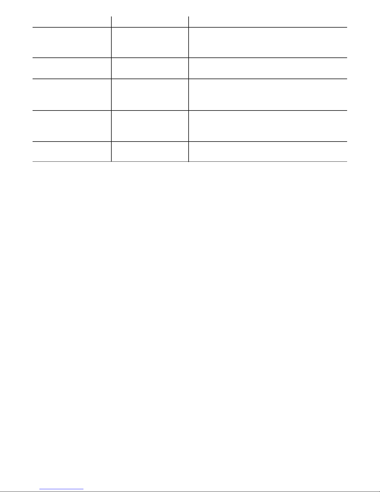
Roll the liner towards the inside in order to hide any excess under the
upper rail. (Rolling it towards the inside ensures that water does not
collect in the flap).
Do not cut the excess – this will cause a pull on the liner!
STAGE 18 - Installation of straight side
upper plates :
oval and round swimming pools.
Now is the time to install the upper plates of the straight sides.
Simply place one plate on each of the straight risers and the sta-
biliser rail. The holes must be aligned and attached with four
screws (8) for each.
Once you have finished all the plates for the straight sides, you
can continue installing those for the curved sides. The central
screws should already be in place. The holes should be aligned.
Finish by screwing the plates to the risers with the two last
screws. Make sure that all the risers (on the curved section as
well as the straight section) are completely vertical.
If any are slanted, you will have trouble installing the upper rails.
The oval upper
plate fits into the
oval riser and is
attached to the
sides with the 2
screws (8)
vis (8)
vis (8)
Inner stabiliser rail
Corner stabiliser
Oval
upper
plate
Oval riser
Screw (8)
Screw (8)
Liner olding pegs
Curved side stabiliser
20.32cm
stabiliser
Right side
stabiliser
Liner
Plastic holding pegs
1/ OVAL :
You should have two different sizes of lips with your oval swimming
pool. The upper lips of 104.77cm (measured from the furthest point
to the furthest point) are for the straight sides of your pool. Note that
the four lips that link the straight sides to the curved sides are
104.77cm lips.
Install all the straight-side lips (104.77cm) first by placing them on
the upper plates and attaching them with four screws (8) four each
lip. All the screws should be positioned first and tightened only when
all the lips are in place. Once all the straight-side lips are done, ins-
tall the shorter lips (101.8) on the curved sides in the same way.
2/ ROUND:
There is only one type of lip.
17
STAGE 19 - Installation of the lips :
oval and round swimming pools.
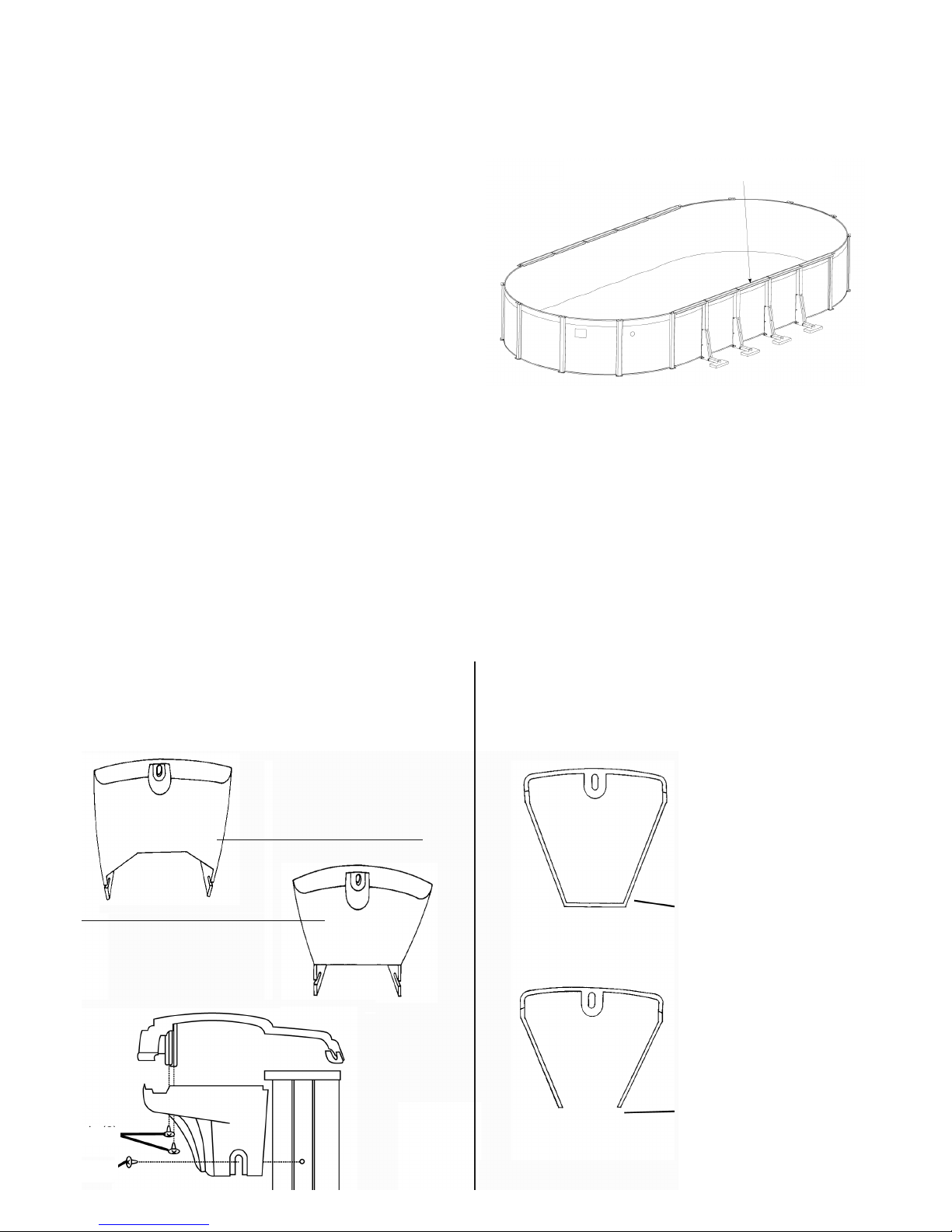
STAGE 20 - Installation of the upper hoods :
oval and round swimming pools.
ON SWIMMING POOLS WITH A LIP OF 15.24CM AND 2-PIECE HOODS, THE HOODS FOR THE
STRAIGHT SIDES ARE THE SAME AS THOSE FOR THE CURVED SIDES.
TWO-PIECE RESIN HOODS WITH ATTACHENTS ON THE
SIDES:
There is a straight support with a square cut-out that goes on the
oval riser, instead of an angle support supplied for the curved ends.
This is attached in the same way as the angle support
LARGE TWO-PIECE RESIN WITH ATTACHMENTS ON THE
FRONT: (DOES NOT INCLUDE POOLS WIT 15.24cm UPPER
RAILS)
Le support angle des extrémités courbés est légèrement plus grand
que le support droit. Le support droit n'est pas rempli à l'arrière.
Attach the lower
half of the hood to
the riser using
screws (8).
Attach the upper
half of the hood to
the lower half using
screws (9).
OVERHEAD VIEW OF
THE ANGLE SUPPORT
FOR CURVED ENDS:
Larger than the straight support.
Closed back. Used on curved-
end risers.
Closed back.
OVERHEAD VIEW OF
STRAIGHT-SIDE SUPPORTS:
Smaller piece, open at the back.
Used on the oval risers.
Open back.
ANGLE SUPPORT FOR
CURVED SIDES:
Use one for each curved-end
riser.
STRAIGHT-SIDE SUPPORT:
Used on the straight side of the pool;
Notice the square cut-out,
used on the oval risers.
vis (8)
vis (9)
Straight side upper rail
Screw (8)
Screw (9)

Failure to comply with the running maintenance instructions can cause serious health risks, notably
for children.
Filtration
In order to eliminate matter in suspension, a good filtration system (sand filter) is essential. During the season in which your pool is in use,
the filtration system should be run every day for a sufficiently long period of time to ensure at least one turnover of the volume of water
every 24 hours (the minimum length of time during for which the filtration system should be run will depend on how much the pool is used
and on the water temperature). It is recommended to divide filtration time into 2 periods (one in the morning, one in the evening).
Examples:
Dimensions volume Filter capacity Minimum filtration time
= v = d = v/d
4.60 x 1.30 20 m37 m3/ h 2.9 hours
7.30 x 3.70 x 1.30 29 m37 m3/ h 4.1 hours
9.15 x 4.60 x 1.30 45 m39.5 m3/ h 4.7 hours
Accessories
The following accessories are essential for satisfactory routine maintenance of your pool: surface accessories (such as strainer), pool-bot-
tom accessories (such as a cleaning machine), and inspection and repair accessories (such as a repair kit).
Chemical Treatment
3 operations are necessary for treating the water:
GCorrection of the water p using an analysis kit and a p corrector. The p (potential hydrogen) indicates the degree of acidity or
alkalinity of the water. The ideal situation for a swimming pool is to have a p as close as possible to that of lacrymal liquid, i.e. 7.4.
GAlgae treatment with an anti-algae product.
GWater disinfection with chlorinated products to destroy micro-organismes.
These treatment and maintenance operations must be done at least once a week to ensure good water quality.
Water treatment products should be stored away from damp, in ventilated premises, and out of reach of children.
NB: Never pour chlorine directly into the swimming pool
Advice:
GPlace a basin of water beside the ladder so that bathers can rinse their feet before going into the pool.
GA bubble sheet will allow you to benefit fully from your pool, because it will heat the water, prevent heat loss during the night, prevent
leaves and insects falling into the water and reduce evaporation of the chlorine.
GDo not dive and do not walk on the lips
Filling and Emptying
We advise you to fill the pool to the level where the top of the skimmer is just above water level.
You are advised not to drain the pool entirely. If you really do need to drain the pool completely, do not do so during periods of strong
wind, and do so as quickly as possible.
You should not leave the pool outside empty.
Special cases and their treatment
Your pool is equipped with a physical filtration system (sand filter, etc.) designed to filter out impurities such as insects, hair, leaves, etc.
Chemical treatment is used in addition to the physical treatment and is vital to keep your swimming water clean.
In normal operating conditions, your swimming pool will need cleaning once a week. You may, however, encounter unusual problems, which
you will be able to put right by following the advice in the following table.
18
21 – Advice for use and maintenance
You are strongly advised not to dismantle your pool. owever, if you really do need to do so, proceed in the reverse order of assem-
bly (this does not apply to semi-embedded and embedded pools). NB: Do not lift the liner while it is still filled with water.
Démonter la piscine en prenant les précautions suivantes :
Take the following precautions when dismantling the pool:
GEmpty the pool by siphoning with a pipe or by means of the sand filter pump.
GWash all items with a soap-based product. Do not use sodium-based products to wash the liner.
GRinse with a water hose and dry all items (to avoid piercing the liner, only clean it within the swimming pool frame; it should be allowed
to dry in the shade, where possible. Do not leave it exposed to the air for a long period).
GIn case of an incident (e.g. pierced liner), it can be repaired easily, even in the water, with a special liner repair glue.
GPut the completely dry liner (without talc added) into an opaque plastic bag and put it into a closed cardboard box. Stock the liner in
a dry place, where there is no danger of freezing, and avoiding contact with any sources of heat.
GRoll up the metal wall without folding it and tie it with a piece of string.
To assemble the swimming pool again, repeat the order of assembly stage in this instruction booklet.
PROBLEM
Cloudy water
Smell of chlorine
Eyes and nose irritated
Green water
Slippery walls and floors
Brown water
Rough-feeling walls
Line of black water
CAUSE
ard water with particles in
suspension.
p level too high.
Chloramine content too high.
Green water: formation or
growth of algae.
Brown water: presence of
organic matter.
ard water.
Grease and deposits on the
water line.
SOLUTION
Adjust the p level.
Place a flocculant in the skimmer or directly in the pool.
Backwash the filter (BACKWAS position) until the water expelled
towards the drain is clean
Adjust the p level.
Backwash the filter (BACKWAS position).
Brush the walls and the skimmer basket.
Adjust the p level.
Carry out shock treatment using a suitable product.
Wash the filter.
Remove deposits using a pool brush or automatic pool vacuum cleaner.
Clean the pool and remove scale from the filter using suitable products.
Adjust the p level.
Add a product to balance the water's degree of hardness.
Clean the water line with a special product.
Place a cartridge of flocculant in the skimmer basket.
19
22 – Dismantling the swimming pool
23 – Advice for winter storage
GDo not empty your pool.
GRemove any floating debris (leaves, twigs, insects, etc.) with a net.
GClean the bottom of the pool with a vacuum brush (or venturi).
GCheck the p with an analysis kit and correct it if necessary.
GAdd a wintering product to the pool; according to the volume of water (see the explanatory note on the label of the product).
GRun the filter for about 4 hours.
GLower the level of the water to below the opening of the skimmer.
GPurge the filtering unit (the pump and the tank) and stock it in a place away from any risk of freezing.
GPut a cap on the overflow pipe and disconnect the pipes (product not supplied in the kit).
GCover the pool with a wintering cover.
REMAR S: If water freezes in an uncovered pool, do not break the ice formed in this way. In very cold weather, you can place
a floating object in your swimming pool to reduce ice formation.
24 - Guarantee
Our pools are guaranteed against any manufacturing defect under normal conditions of use.
This guarantee is limited to replacement of parts recognised to be defective, by your retailer.
IMPORTANT! For guarantee coverage to be granted, you should keep proof of purchase bearing the retailer’s stamp and the date
of purchase.

Thank you for purchasing an ABAK swimming pool.
This swimming pool will guarantee you exceptional quality and reliability and
we hope that it will meet your expectations.
TRIGANO JARDIN
Le Bo lay - 41170 CORMENON
123714 - Trigano Jardin - 303 773 923 RCS Paris - document non contactuel - 02/2008
S w i m m i n g P o o l s
Other manuals for OSMOSE Oval
1
This manual suits for next models
1
Table of contents
Other Trigano Jardin Swimming Pool manuals


Popular Swimming Pool manuals by other brands


Blue Wave
Blue Wave NB19890 instruction manual

Blue Wave
Blue Wave MONTAUK NB19836 instruction manual

Radiant Pools
Radiant Pools Keystone Assembly manual

Chad Valley
Chad Valley 3106066 owner's manual

Intex
Intex Prism 128712GN owner's manual

Metal Arsenal
Metal Arsenal ECCOTARP ET LARGE 111 Instructions for use