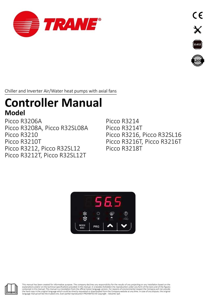
TRIGEM TPS-7500 Supplement

GNINRAW
●●
●
●●
serudecorpecivresynamrofreptonoD
●●
●
●●
.ylhguorohtlaunamsihtgnidaererofeb
●●
●
●●
semitllataelbaliavalaunamsihtpeeK
●●
●
●●
.lanimretehtgnicivresnehw
MODEL
TPS-7500
POS CONTROLLER
INSTALLATION & SERVICE MANUAL

MODEL TPS-7500
INSTALLATION & SERVICE MANUAL
Published by
TriGem Computer, INC.
Notice
1TriGem Computer, INC. reserves the right to make changes to the contents of
this publication without prior notice.
2TriGem Computer, INC. reserves the right to make changes to equipment and
specifications without obligation or notification.
3Some equipment nomenclature and abbreviations used here may differ from
that contained in other TriGem publications.
4TriGem Computer, INC. will not be held responsible for any accidents for
damage caused by procedures not in compliance with those in this
publication, or by actions that did not heed to the cautions.
5This publication, or parts thereof, may not be reproduced in any form without
prior written permission of TriGem Computer, INC. Unauthorized use or
distribution of this publication is prohibited.
© TriGem Computer, INC., 1999

Revision Record
eussI etaD skrameR
A209/9 gnitnirptsriF
ATTENTION
This equipment has been tested and found to comply with the limits for a Class
A digital device, pursuant to Part 15 of the FCC Rules. These limits are designed
to provide reasonable protection against harmful interference when the
equipment is operated in a commercial environment. This equipment generates,
uses, and can radiate radio frequency energy and, if not installed and used in
accordance with the instruction manual, may cause harmful interference to radio
communications. Operation of this equipment in a residential area is likely to
cause harmful interference in which case the user will be required to correct the
interference at his own expense.
This digital apparatus does not exceed the Class A limits for radio noise
emissions from digital apparatus set out in the Radio Interference Regulations of
the Canadian Department of Communications.

SICHERHEITSHINWEISE
Die Steckdose zum Anschluß dieser Registrierkasse muß nahe dem Gerät
angebracht und leicht zugänglich sein. Öffnen des Gehäuses nur durch Service
Personal.
SAFETY INDICATION
The socket for this Cash Register must be installed near the equipment and must
be easily accessible. The housing may only be opened by service staff.
INDICATION POUR LA SECURITE
La prise de courant de cette ordinateur deît être installée près de l’équipement et
doît être facile à accéder. La couverture ne peut être ouverte que par le personnel
de service.

Important Safety Instructions
The following instructions pertain to the risk of fire, electric shock or bodily
injury. Please read all of these instructions carefully.
1 Save these instructions for later use.
2 Follow all of the instructions and warnings marked on this product or
included in this manual.
3 Do not use this computer on an unstable cart, stand or table. The product may
fall, causing serious damage to the product.
4 Slots and openings in the cabinet and the back have been provided for
ventilation. To ensure the reliable operation of your computer, and to protect
it from overheating, these openings must not be blocked or covered. Don't
use this product on a bed, sofa, rug or other similar surface. This product
should never be placed near or over a radiator or heat register. This product
should not be placed in a built-in installation unless proper ventilation is
provided.
5 Never push objects of any kind into the computer through the cabinet
openings, as they may touch dangerous voltage points or short out parts that
could result in a fire or electrical shock. Never spill liquid of any kind on the
product.
6 This computer should only be connected to the AC power source indicated on
your computer system's information label. If you are not sure of the type of
AC power available, consult your dealer or local power company. Only
connect this computer to a power outlet that matches the power requirements
of this computer.
7 Do not allow anything to rest on the power cord. Do not locate this product
where people will walk on the cord.
8 If you have to use an extension cord with this computer, make sure that the
total amperage rating of all equipment plugged into it does not exceed the
amperage rating of the extension cord. Also, make sure that the total of all
products plugged into the main AC power outlet does not exceed 15 amps.
9 Unplug your computer from the main electrical power outlet before cleaning.
Do not use liquid cleaners or aerosol cleaners. Use a damp cloth for cleaning.

10 Do not use this computer near water.
11 This product is eqiupped with a 3-wire grounding type plug, a plug having a
third (grounding) pin. This plug will only fit into a grounding-type power
outlet. This is a safety feature. If you are unable to insert or replace your
obsolete outlet, contact your electrician to replace your obsolete outlet. Do
not defeat the purpose of the grounding-type plug.
Maintenance
If the product does not operate normally, adjust only those controls that are
covered by the operating instructions. Improper adjustment of other controls may
result in damage and may require extensive repair work to restore the product to
normal operation.
Unplug this product from the main power outlet and call for service under any of
the following conditions:
a If the power cord or plug is damaged or frayed.
b If liquid has been spilled into the product.
c If the product has been exposed to rain or water.
d If the product has been dropped or the cabinet has been damaged.
e If the product exhibits a distinct change in performance, indicating a need for
service.
Stop
If you ever have to remove the main system unit cover, observe the following
precautions:
a The power supply cord must be unplugged before the main system unit cover
is removed. (Separe le cordon d'alimentation et puis enleve le couvercle.)
b Once removed, the cover must be replaced and screwed in position before the
power supply cord is plugged back in. (Apres le couvercle a enleve, visse le
couvercle en place et remettre le cordon d'alimentation.)

Wichtige Sicherheitsvorschriften Unbedingt
Beachten
Allgemeine Sicherheit
Die nachfolgenden Anweisungen betreffen die Gefahr von Verletzungen durch
elektrische Spannung, Feuer und mechanische Einwirkung. Bitte lesen Sie diese
Anweisungen sorgfältig.
1 Beachten Sie alle Hinweise, die am Gerät selbst angebracht oder in den
zugehörigen Handbuchrn vermerkt sind.
2 Stellen Sie das Gerät an einem sicheren, stabilen Arbeitsplatz auf.
3 Am Gerät angebrachte Öffnungen (Schlitze und sonstige Öffnungen) dienen
der Belüftung des Gerätes. Um ein zuverlässiges Arbeiten des Geräts zu
gewährleisten und um Überhitzung zu vermeiden, müssen diese Öffnungen
unbedingt freigehalten werden. Betreiben Sie das Gerät nie auf Betten, Sofas
oder anderen, weichen Unterlagen.
4 Stecken keine Gegegenstände (Schraubenzieher, Büsroklamern etc.) in die
Öffnungen. Sie wurden damit Kurzschlüsse herbeiführen die zur Zer störung
des Geräts führen, sich der Gefahr eines Stromschlages aussetzen oder das
Gerät in Brand setzen.
5 Das Gerät darf nur an vorschriftmäßige Steckdosen mit der auf dem Gerät
angegebenen Netzspannung angeschlossen werden. Wenn Sie nicht sicher
sind, welche Netzspannung richtig ist, wenden Sie sich an den Lieferanten
des Gerätes oder an das zuständige Elektriziträtswerk. Bitten nur an
Genügend stark abgesicherte Steckdosen anschließen, die der Leis
tungsaufnahme des Gerätes entsprechen.
6 Auf das Netzanschlußkabel dürfen keine Gegenstände gestellt werden. Legen
sie das Netzkabel so, daßniemand darauftreten oder darüber stolpern kann.
7 Wenn Sie Verlängerungskabel benutzen, müssen Sie sicher sein, daß die
gesamte Leistungsaufnahme nicht größer ist als das Verlängerungskabel
zulaßt. Der gesamte Stromverbrauch aller angeschlossenen Geräte darf nicht
mehr als 15 A betragen.

8 Wenn Sie das Gerät reinigen, muß das Netzkabel aus der Steckdose gezogen
werden.
9 Das Gerät dürfen Sie nicht in der Näh von Wasserleitungen benutzen.
Wartung Des Computers
Wenn der Computer nicht ordnungsgemäß arbeitet, dürfen Sie nur die
Einstellungen vornehmen, die im Handbuch genannt werden. Andere
Einstellungen oder Verän derungen können den Computer beschädigen oder
zerstören. Umfangreiche und kostspielige Reparaturen würden notwendig
werden, um das Gerät wieder betriebsfähig zu machen.
Ziehen Sie den Netzstecker aus der Steckdose und verständigen Sie den
zuständigen Kundendienst bei folgenden Storungen:
a Netzkabel ist defekt oder strak abgenutzt.
b Flüssigkeit ist in das Gerät geschüttet worden.
c Das Gerät war Regen oder Leitungswasser aus-gesetzt.
d Das Gerät ist heruntergefallen oder das Gehäuse ist beschädigt.
e Das Gerät arbeitet nicht mehr richtig.
Achtung
Wenn Sie das Gerät Öffnen müssen (Abnahme der verschraubten Haube), ist
unbedingt folgendes zu beachten:
a Das Netzkabel muß aus der Steckdose gezogen werden und zwar bevor Sie
das Gerät Öffnen.
b Die Haube muß wieder monitiert und verschraubt werden. Erst dann darf das
Netzkabel wieder eingesteckt werden.

Safety Instruction
Ensure that the appropriate power cord is supplied with personal computer. If the
power cord is not supplied with personal computer, use the correct listed cord
sets as below:
gnitaR epyT etoN
.niMA01,V521
3/GWA81
TVS
m5.4.xaM
gnol
drocnodedlomhtiwdetanimretdneenO-
.ydobrotcennoc
.P51-5amenahtiwpacgulptnemhcattA-
.niMA6,V052
3/GWA81
TVS
m5.4.xaM
gnol
drocnodedlomhtiwdetanimretdneenO-
.ydobrotcennoc
.P51-6amenahtiwpacgulptnemhcattA-

CONTENTS
Chapter 1
Introduction
Features ........................................................................................................ 1-1
Video and Audio Drivers ...............................................................................1-2
Optional Equipment ...................................................................................... 1-3
Names and Functions of the System .............................................................. 1-4
Front Panel ............................................................................................ 1-4
Back Panel ............................................................................................ 1-6
Chapter 2
Setting Up Your System
1 Selecting a Site ..........................................................................................2-1
2 Checking the Voltage Setting ..................................................................... 2-2
3 Connecting a Monitor ................................................................................ 2-3
4 Connecting a Printer or Other Device ......................................................... 2-5
Using the Parallel Interface ....................................................................2-5
Using the Serial Interface ...................................................................... 2-6
5 Connecting the Keyboard ........................................................................... 2-7
6 Connecting the Mouse ............................................................................... 2-8
7 Connecting Audio Devices ......................................................................... 2-9
8 Connecting USB devices .......................................................................... 2-10
9 Connecting the POS Devices .................................................................... 2-11
TPS-7500 ............................................................................................2-11
Connecting Dust Rear Cover................................................................2-12
Connecting CDP .................................................................................. 2-13

10 Connecting the Power Cord ...................................................................2-14
11 Turning On and Off the Computer.......................................................... 2-15
Turning On the Computer ................................................................... 2-15
Turning Off the Computer ...................................................................2-16
Chapter 3
Using Your Computer
Installing Windows 95 or Other Operating Systems ...................................... 3-1
Using a Diskette Drive ................................................................................... 3-1
Write-protecting Diskettes .................................................................... 3-1
Inserting and Removing Diskettes .........................................................3-3
Formatting Diskettes ............................................................................. 3-3
Using the CD-ROM Drive .............................................................................. 3-4
Using the Hard Disk Drive ............................................................................. 3-5
Using Special Keys on the Keyboard ............................................................. 3-6
Using the Mouse ........................................................................................... 3-7
Resetting the Computer ................................................................................ 3-8
Chapter 4
Using the SETUP Program
About the SETUP Program ............................................................................. 4-1
Starting the SETUP program .......................................................................... 4-2
Selecting Options ................................................................................. 4-2
Setup ............................................................................................................ 4-3
Standard Setup ..................................................................................... 4-3
Advanced Setup ................................................................................... 4-5
Chipset Setup ....................................................................................... 4-7
Power Control Setup ............................................................................. 4-8
PCI/PnP Setup ....................................................................................... 4-9
Peripheral Setup .................................................................................. 4-11

Utility .......................................................................................................... 4-12
Detect IDE ..........................................................................................4-12
Color Set .............................................................................................4-12
Security ....................................................................................................... 4-13
Supervisor / User ................................................................................ 4-13
Anti-Virus ........................................................................................... 4-16
Default ........................................................................................................4-16
Original .............................................................................................. 4-16
Optimal .............................................................................................. 4-16
Exiting the SETUP Program .......................................................................... 4-17
Chapter 5
Installing and Removing Options
Locating the Internal Components ................................................................ 5-2
Motherboard Features ................................................................................... 5-3
Motherboard and Riser Card Connectors and Sockets .................................... 5-4
Removing the Cover ..................................................................................... 5-5
Replacing the Cover ......................................................................................5-7
Option Cards ................................................................................................ 5-8
Installing an Option Card ...................................................................... 5-8
Removing an Option Card .................................................................. 5-11
Changing the Jumper Settings ..................................................................... 5-13
Memory Modules ....................................................................................... 5-15
Installing Memory Modules ................................................................ 5-16
Removing Memory Modules...............................................................5-17
Microprocessor Chip ................................................................................... 5-18
Replacing the Microprocessor Chip ..................................................... 5-18
IDE Drives ................................................................................................... 5-20
Replacing the Hard Disk Drive ............................................................ 5-21
Replacing the CD-ROM Drive .............................................................. 5-26
Replacing the Battery .................................................................................. 5-30
After Installing Options ............................................................................... 5-31

Chapter 6
Installing the Video Drivers
Installing the Video Drivers for Microsoft Windows 95 .................................. 6-1
Using Display Modes .................................................................................... 6-6
Chapter 7
Installing the Audio Drivers
Installing the Audio Drivers for Microsoft Windows 95................................. 7-1
CWBMIX.EXE ................................................................................................ 7-5
MMX
TM
Technology Enabled Mixer................................................................ 7-6
Chapter 8
Installing the USB Supplement
Installing the USB Supplement for Windows 95 ............................................ 8-1
Appendix A
Specifications
Chipset ........................................................................................................ A-1
CPU and Memory ......................................................................................... A-1
Controllers ................................................................................................... A-3
Interfaces ..................................................................................................... A-4
Power Supply ............................................................................................... A-5
Mass Storage ............................................................................................... A-6
DMA Channels ............................................................................................. A-6
Interrupts ..................................................................................................... A-7

Appendix B
Specification and Setting of I/O Card for POS
Specification..................................................................................................B-1
Board Layout ................................................................................................B-2
Installing Hardware .......................................................................................B-2
Setting Address ............................................................................................B-3
Software Driver .............................................................................................B-3
Pin Assignment .............................................................................................B-3
On failure during installation .........................................................................B-4
Setting POS PLU Key Board...........................................................................B-4
Appendix C
Compliance Statements
FCC Compliance Statement ...........................................................................C-1
Battery Warning Instruction ...........................................................................C-2
Fuse Warning Instruction ...............................................................................C-3
Laser Product ................................................................................................C-4

1-11-1
1-11-1
1-1
Introduction
Chapter 1
Introduction
Introduction
Features
Your profile system provides the following built-in features:
Built-in type 7 Pentium® OverDrive
TM
processor socket
Intel® Pentium® P54C(S)/133, 166 or 200 MHz, P55C-MMX
TM
/166, 200 or
233 MHz, AMD K5
TM
, or K6
TM
/166 or 200 MHz, Cyrix M2/PR166 or PR200,
IDT C6/180 or 200 MHz microprocessor support
256KB or 512KB of Pipeline Burst SRAM external(L2) cache (factory setting
according to the system type)
16MB of internal memory, expandable to 256MB using DIMMs
Two built-in PCI Bus Mastering Enhanced IDE connectors
Two USB (Universal Serial Bus) connectors
Two built-in serial ports and one built-in parallel port
Built-in IBM PS/2 compatible keyboard and mouse ports
Built-in microphone jack, audio line-in jack, and audio line-out jack
Two 16-bit ISA bus slots and one 32-bit PCI slot on the riser card (one slot
shared)

1-21-2
1-21-2
1-2
Introduction
Built-in video connector
Support for Ultra DMA (ATA/33) hard disk drives for increased performance and
data integrity
SiS 5598B UMA (Unified Memory Architecture) graphics controller built in the
SiS 5598 chip on the motherboard
Built-in 16-bit CS 423X audio controller
Support video shared memory from 1 MB to 4 MB through SETUP
Supervisor and user passwords function
Diskette drive write protection
Plug-and-Play (PnP) compatible BIOS
System and video BIOS shadow RAM
Support for Advanced Power Management(APM)
Bootable with CD-ROM drives
DMI (Desktop Management Interface) 2.0 compliance (Requires DMI-enabled
components)
Video and Audio Drivers
Your system has a SiS 5598B video controller and a Crystal 423X audio controller,
which is prepared video and audio drivers respectively for the following operating
systems:
Microsoft Windows 3.1x
Microsoft Windows 95
Microsoft Windows NT
OS/2
For information on installing video and audio drivers, see Chapter 6 and Chapter 7
respectively.

1-31-3
1-31-3
1-3
Introduction
Optional Equipment
You can utilize the following options for the computer and easily upgrade your
computer by installing memory modules, a microprocessor chip, a hard disk drive, or
CD-ROM drive.
System Memory
You can expand the computer's memory up to 256MB by adding 8MB, 16MB,
32MB, 64MB, or 128MB EDO DRAM or SDRAM DIMMs.
Processor
You may replace the existing microprocessor with a new one to enhance the speed
and performance of your computer. You can use an Intel Pentium P54C, P55C-MMX,
AMD K5 or K6, Cyrix M2, or IDT C6 processor as compatible processors to upgrade
your microprocessor.
Drives
The three drive bays in your system consist of:
one 5.25-inch external bay for a CD-ROM drive
one 3.5-inch external drive bay that is dedicated to a 3.5-inch diskette drive
one 3.5-inch internal bay for a 3.5-inch hard disk drive
Option Cards
You can install a variety of option cards such as 3D graphics cards, LCD cards, fax/
modem cards, or LAN cards in your system, but install only two option cards.
Battery
You can replace the battery on the motherboard with coin-cell CR2032-type one.

1-41-4
1-41-4
1-4
Introduction
Names and Functions of the System
The following section describes names and functions of the system.
Front Panel
The illustration below shows the front panel of the system.
The shape and type of the CD-ROM drive illustrated below may be
different from those of your CD-ROM drive.
Note
Note
headphone jack
diskette drive
access indicator
headphone
volume control
eject button
diskette drive
CD-ROM drive
(optional)
disc drawer
busy indicator
play/skip
button
open/close/
stop button
emergency
eject hole
hard disk drive
access indicator
power indicator
power button
drive bay
access door

1-51-5
1-51-5
1-5
Introduction
Power indicator [ ]
Lights up when the computer is on.
Hard disk drive access indicator [ ]
Lights up when the hard disk drive is reading data from or writing data to the drive.
Power button [ ]
Press to turn the computer on or off. Do not turn the power on or off with a disk in
the drive. Data on the disk may be damaged.
3.5-inch diskette drive
Accepts 3.5-inch floppy diskettes.
CD-ROM drive (optional)
Used to play music CDs, photo CDs or video CDs, or to load software packages onto
the hard disk drive.
Headphone jack
3.5 mm jack for monitoring the audio signal from audio CDs.
Busy indicator
The busy indicator lights during initialization and data-read operations.
Emergency eject hole
Insert a rod here to eject the drawer manually, or when there is no power.
Play/skip button
When the audio CD is in the disc drawer, pressing this button will start playing audio
CDs from the first track on. If the audio CD is playing, pressing this button will skip
to the next track of an audio CD.
Open/close/stop button
Press this button to open or close the CD tray. The button works only when power is
applied to drive. If the audio CD is playing, pressing the button will stop it, and
pressing it again will open the tray.

1-61-6
1-61-6
1-6
Introduction
DRA COM7 CDP SCN
Disk drawer
Accepts a CD-ROM disc on its tray.
Headphone volume control
Adjust the headphone sound level.
Back Panel
The illustration below shows the back panel of your system.
Voltage selection switch
Selects between 115 and 230 VAC operation. This switch must be set to match the
AC power available at your location.
Set correctly the voltage selection switch. Otherwise, your system may be
damaged. Make sure that this switch is set correctly for your location before
turning on your computer.
Caution
Caution
power inlet
microphone jack
power supply
fan vent holes
USB connectors
option card slot covers
video port
serial port (COM1)
line-out jack
serial port (COM2)
parallel port
PS/2 keyboard connector
PS/2 mouse connector
voltage selection switch
line-in jack
POS I/O PORT
Table of contents
Popular Controllers manuals by other brands

Philadelphia Scientific
Philadelphia Scientific iBos Charger-Splitter installation manual
Gantner
Gantner BENZIG M1 Fancier Manual
Supmeter
Supmeter BST100-E11 Operation manual
Batronix
Batronix BX32 BATUPO manual

Spectrum Illumination
Spectrum Illumination MONSTER BRAIN user manual
SYCLOPE
SYCLOPE DOUBLEAU Programming instructions
