Trigon Electronics Telalarm HF-2BB User manual

255 Glider Circle • Corona, CA 92880
www.TrigonElectronics.com
March 1, 2004
Telalarm HF-2BB
®
Handsfree Emergency Autodial Telephone
INSTALLATION
and
OPERATIONAL INSTRUCTIONS
(Firmware revision #020700 Rev. A HF2XTRA)
with 10 number rollover

Page 2
HF-2BB
TABLE OF CONTENTSTABLE OF CONTENTS
TABLE OF CONTENTSTABLE OF CONTENTS
TABLE OF CONTENTS
INTRODUCTION ..................................................................................... 3
PRODUCT OVERVIEW .......................................................................... 3
MOUNTING .............................................................................................. 4
WIRING ..................................................................................................... 4
WIRING DIAGRAM ................................................................................ 5
PROGRAMMING
Entering Program Mode .......................................................................... 6
Setting Operational Modes...................................................................... 6
EnteringAutodialed Telephone Numbers ............................................... 6
VerifyingAutodialed Telephone Number................................................ 6
Setting the Site ID Number ..................................................................... 7
Changing Program Access Number ........................................................ 7
Setting the Relay Duration Timer ........................................................... 7
Setting Incoming Ring Count.................................................................. 7
Setting Dial Mode ................................................................................... 7
Setting Call Legnth ................................................................................. 7
DTMF Echo Test ...................................................................................... 7
Cycling Relays ...................................................................................... . 7
OPERATION
STANDARD Mode................................................................................. 8
EMERGENCY Mode ............................................................................ 8
TROUBLE SHOOTING GUIDE
General .................................................................................................... 9
CONDENSED GUIDE TO USE and PROGRAMMING
Security Dept. Operation......................................................................... 10
Standard Mode ........................................................................................ 10
Emergency Mode .................................................................................... 10
Programming the Unit............................................................................. 10
HF-2 KIT WIRING DIAGRAM .............................................................. 11
Revision 11501 Approved

Page 3
HF-2BB
INTRODUCTIONINTRODUCTION
INTRODUCTIONINTRODUCTION
INTRODUCTION
PRODUCT OVERVIEWPRODUCT OVERVIEW
PRODUCT OVERVIEWPRODUCT OVERVIEW
PRODUCT OVERVIEW
If you are using this manual as a programming guide
after the initial installation, you may find the TABLE OF
CONTENTS useful in locating the particular
programming procedure you need.
This manual contains all the information required to
installand program theTRIGON HF-2. If youare using
this manual to install this unit, it is very important to
read all the sections in order.
You should read these instructions before you begin
installation. This will insure that everything is done
efficiently.
The Telalarm HF-2 is a multi-number emergency auto
dialer. Upon pressing the button, the HF-2 dials a
programmed telephone number. If the number dialed
is busy or does not answer, the HF-2 will hang up and
dial the next programmed number, up to a maximum
of 10. If the last programmed number is busy or does
not answer, the HF-2 will rollover and start the dialing
process again with the first phone number.
The HF-2 comes standard with one output relay. This
relay is pre programmed to close when the help button
is pressed in order to turn on a strobe light.
There are two Modes of Operation incorporated in the
HF-2:
1. TheEmergency Mode causesrelayactivation
at the moment the start button is pressed. This
mode is best suited for safety use when camera
and lighting control is desired.
2. Optional Ring Down Mode:
When call call button is pressed, the HF-2 seizes
the telephone line and waits for the PBX to dial a
preprogrammed number. This call may only be
terminated by the called party.
A Site I.D. code feature provides for unit identification.
The Site I.D. code is a programmable four digit code
that is transmitted by the HF-2 when it receives a
command from the called party. This code, when
interpreted by a Trigon DTMF Decoder, will identify
the calling unit.
.
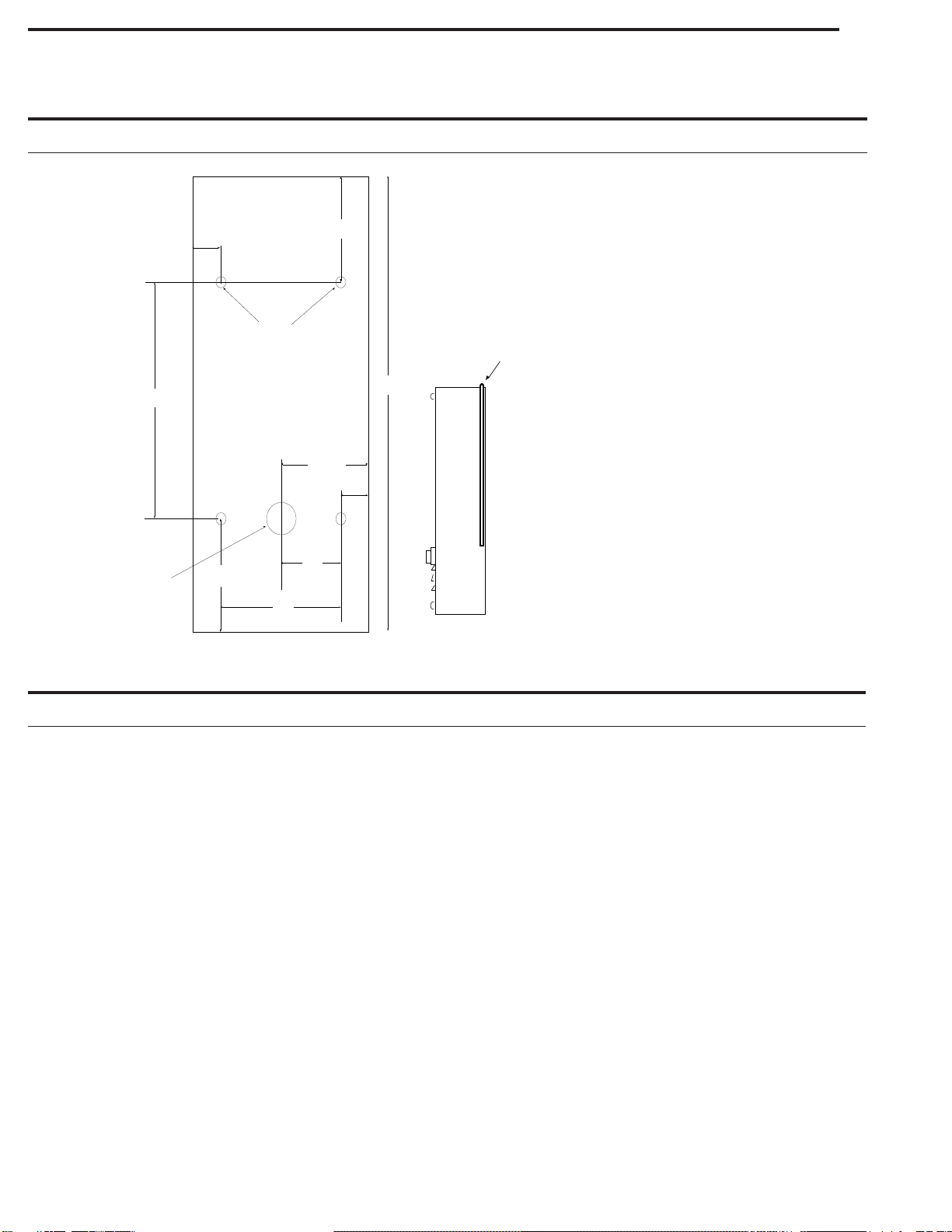
Figure 1
TRIGON
TRIGON ELECTRONICS
ORANGE CA.
CALL
HF-2
12"
4.2" 2.0"
Telephone Line-
Voice Grade 24 to 48V
22 AWG;Shielded
or Twisted,2 Conductor
Camera, Dooror Gate
Secondary
Relay
SerialPrinter
(18 AWG; Shielded, 3 Conductor)
Postal
Lock
Box
Primary
Output
Relay
Main Entrance
Power Cabling -
Shielded or Twisted,
2 Conductor,
18AWG up to 250'
16AWG up to 500'
Alarm
Shunt
Relay
Page 4
HF-2BB
WIRINGWIRING
WIRINGWIRING
WIRING
MOUNTINGMOUNTING
MOUNTINGMOUNTING
MOUNTING
avoid ground loops, do not ground the shield at both
ends. Use 600V insulated wire for this installation.
7. Isolate the Telco phoneline from 12 VAC power
wires. This will prevent 60 Hz hum from occurring
on the phoneline. Use 22 AWG wire on Telco line
run distances of up to 2400 feet. Consult the factory
for distances greater than 2400 feet.
8. Power Relays 1 and 2 are dry contact, Form C type,
rated for 5 AMPS @ 30 VDC/ 250VAC.
9.The Shunt relay is a low-power (4 watt) reed relay.
It can be used for temporary alarm switch bypass,
video camera activation, etc. The Shunt relay
activates with the #1 or #2 power relay, and
deactivates thirty seconds after relay release.
10.Connect printer wiring to the RS-232 port (Printer
IN to RS-232 OUT, Printer BUSY to RS-232 DSR,
Printer COM to RS-232 COM).
11. If all wiring and grounding is completed, mount the
faceplate onto the backbox.
1.Use the wiring diagram (Fig. 3) for wire connection
information.
2.Do not power any other device from the Trigon’s
12 VAC transformer. If a substitute transformer is
used, be sure it is rated 12 VAC, 40VA, UL Class 2
listed. The 12 VAC input power wires should be
18AWG, 600V, insulated wire. This should be
sufficient for distances up to 200 feet.
3. Do not energize wires until installation is completed.
4. Ground the unit by attaching a separate 12 AWG
ground wire to the ground location on the terminal
block. This ground wire should go to a grounding
rod or grounded metal conduit.
5. Trigon recommends that an EMI filter (Cornell-
Dubilier ModelAPF 1021 or equivalent) be mounted
between the 12 VAC transformer output and the unit.
EMI/RFI filters are available from Trigon. Mount
the filter as close to the unit as possible. Ground the
filter to the same point as unit ground.
6. Shielded cable is recommended. Ground the
shielding to the same point as the unit and filter. To
Arrangements must be made with the local telephone
company for installation of a standard voice-grade
telephone line (touch-tone or rotary) as close to the unit
mounting location as possible. The telephone company
may require the following information.
FCC Registration No..................1Z8898-62546-DI-T
Ringer Equivalence..............................................0.8B
Connector............................................Terminal Block
The unit is designed to be as weather resistant as
possible. Wedo however recommend someshelter from
direct rain and sunlight. An overhang is usually
sufficient. Bolt the back plate (Fig. 2) to the mounting
surface using the four .312" holes in the chassis. Feed
the wiring through the access hole in the rear of the
back plate. At this point, the wiring should NOT be
live (energized).
Note: If used in extreme weather, a bead of silicon
sealant should be run around the outside top two thirds
of the unit, after the front case is secured.
(Fig. 2b).
.52" 3.62"
+
+
11.80"
5.38"
2.80"
+
+
3.0"
.52"
1.5"
2.02"
1 Hole
.88" Dia.
4 Holes
.312" Dia.
Note: Mount backplate with 1" wire entry hole
toward the bottom. Seal the opening with a
silicone sealant before attaching backplate to surface.
Figure 2b
Seal top 2/3 of case
to mounting surface.
Side View
Figure 2
Page 5
HF-2BB
WIRING DIAGRAMWIRING DIAGRAM
WIRING DIAGRAMWIRING DIAGRAM
WIRING DIAGRAM
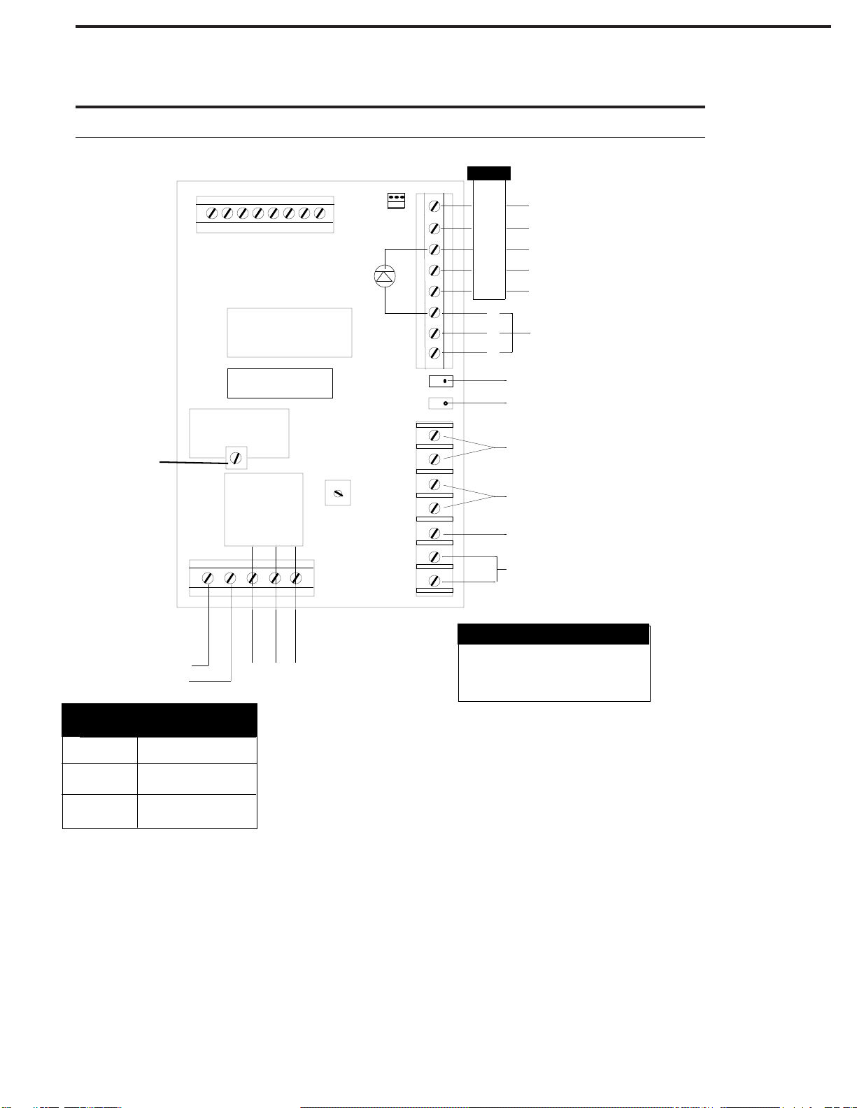
Figure 3
0-250'
500' +
18 AWG; Shielded
16 AWG; Shielded
14 AWG; Shielded
Input power cabling
250 to 500'
IN
OUT
DSR
COM
RS-232
CARD READER
EARTH GROUND
TELEPHONE LINE
EARPHONE
MOUTH
SPEAKER (HF-2)
MICROPHONE (HF-2)
MICROPROCESSOR
AUDIO
SPEAKER
VOLUME
PRIMARY
RELAY
12V AC / DC NO C NC
INPUT
POWER
5 Amp MAX
MEMORY
P
S
G
Telephone line cabling
Voice Grade 24 to 48V
22AWG; Shielded or
Twisted up to 2400'
Busy
Com
Printer
In
RTS
Microphone
Sensitivity
Adjustment
PG
TELALARM HF-2

Page 6
HF-2BB PROGRAMMING INFORMATIONPROGRAMMING INFORMATION
PROGRAMMING INFORMATIONPROGRAMMING INFORMATION
PROGRAMMING INFORMATION
General Programming Information
The "Initial Setup" for the HF-2 has been programmed
at the factory. These factory default settings may be
changedto better suit yourparticularapplication. If
you decide to alter these settings, follow the instructions
below. It is important that each programming step be
taken in order. When reprogramming a specific feature,
you must always enter the programming mode first. You
may then go to the appropriate procedural steps for the
changes desired.
Record below the autodialed numbers to be programmed
into the HF-2.
Autodialed Numbers
Primary Auto dial Number (16 digit max)
__ __ __ __ __ __ __ __ __ __ __ __
Second Auto dial Number (16 digit max)
__ __ __ __ __ __ __ __ __ __ __ __
Third Auto dial Number (16 digit max)
__ __ __ __ __ __ __ __ __ __ __ __
Fourth Auto dial Number (12 digit max)
__ __ __ __ __ __ __ __ __ __ __ __
Fifth Auto dial Number (16 digit max)
__ __ __ __ __ __ __ __ __ __ __ __
Sixth Auto dial Number (16 digit max)
__ __ __ __ __ __ __ __ __ __ __ __
Seventh Auto dial Number (16 digit max)
__ __ __ __ __ __ __ __ __ __ __ __
Eighth Auto dial Number (16 digit max)
__ __ __ __ __ __ __ __ __ __ __ __
Ninth Auto dial Number (16 digit max)
__ __ __ __ __ __ __ __ __ __ __ __
Tenth Auto dial Number (16 digit max)
__ __ __ __ __ __ __ __ __ __ __ __
Site ID Number-if required Number (4 digits)
__ __ __ __
PROGRAMMINGPROGRAMMING
PROGRAMMINGPROGRAMMING
PROGRAMMING
(B) Setting Operational Modes:
Except when noted, each of the following program
commands will result in two (2) tones (high/low)
signifying their completion and acceptance.
Ring Down Mode
1. Unit must be in Program Mode.
2. Press '7' then press 4 to set unit for ring down
mode.
3. If desired, exit Program Mode by pressing '#'
(wait for two second tone).
4. To terminate call, press '7'.
(A) To Enter Program Mode:
1. Call the telephone number of the unit.
2. Listen for the two second tone.
3. Enter # then the unit's Program Code.
4. If desired, exit Program Mode by pressing '#'
(wait for two second tone).
5. To terminate call, press '7'.
If the unit is new, use the preset factory code. (Factory
code is 9753).
Emergency Mode, causes one relay to be momentarily
activatedwhen a call isplaced(for camera call-up) while
the other relay activates continuously throughout the
call (for lighting, etc.).
1. Unit must be in Program Mode.
2. Press '7' then press '1' to set unit for
Emergency Mode.
3. If desired, exit Program mode by pressing '#'
(wait for two second tone).
4. To terminate call, press '7'.
1. Unit must be in Program Mode.
2. Press '2' then '1' (wait for tone) and enter the
first phone number. Press '#' when complete.
Press '2' then '2' (wait for tone) and enter the
second phone number. Press '#' when complete.
If more numbers are needed press '2' then '3'
(wait for tone) and so on for up to 10 phone
numbers. Press '#' when complete.
3.If desired, exit Program Mode by pressing '#'
(wait for two second tone).
4.To terminate call, press '7 '.
(D) Verifying Telephone Numbers:
(C) Setting the Primary and Backup Telephone
Numbers:
1. Unit must be in Program Mode.
2. Press ' ' then press '1' to verify the first phone
number entered.
3. Press ' ' then press '2' to verify the second
phone number entered etc.
4. If desired, exit Program Mode by pressing '#'
(wait for two second tone).
5. To terminate call, press '7'.
✽
✽

Page 7
HF-2BB
PROGRAMMING, Cont.PROGRAMMING, Cont.
PROGRAMMING, Cont.PROGRAMMING, Cont.
PROGRAMMING, Cont.
This number identifies the unit upon request from a
central office.
(E) Setting the Site ID Number:
1. Unit must be in Program Mode.
2. Press '1' .
3. Enter a four digit number.
Youwill hear two'beeps' indicating command accepted.
4. If desired, exit Program Mode by pressing '#'
(wait for two second tone).
5. To terminate call, press '7'.
(F) Changing ProgramAccess Number:
Thiswill changethe factory presetnumberof'9753'.
1. Unit must be in Program Mode.
2. Press '3'.
3. Enter a new four digit number.
Youwill hear two'beeps' indicating command accepted.
4. If desired, exit Program Mode by pressing '#'
(wait for two second tone).
5. To terminate call, press '7'.
(G) Setting the Relay Duration Timer:
This will set the length of time the Primary and
Secondary relays remain activated. The duration can
be set from 1 to 45 seconds.
Thedurationis set by enteringthenumber of five-second
intervals desired (2= ten seconds).
1. Unit must be in Program Mode.
2. Press '0'.
3. Enter the number of 5 sec. intervals required.
Youwill hear two'beeps' indicating command accepted.
4. If desired, exit Program Mode by pressing '#'
(wait for two second tone).
5. To terminate call, press '7'.
Note: If '0' is entered in step 3, relays will pulse for one
second.
(H) Setting Incoming Ring Count:
Entering a digit value of 1 to 9 will set the number of
rings the unit will count before answering an incoming
call.
1. Unit must be in Program Mode.
2.Press '5'.
3. Enter the number of rings desired ( 1 to 9).
or
4. Enter '0' if an audible ring is desired from the
HF-2 whenever it is called.
You will hear two 'beeps' indicating command accepted
5. If desired, exit Program Mode by pressing '#'
(wait for two second tone).
6. To terminate call, press '7'.
Note: If '0' was programmed for an audible ring, the call
may be answered by pressing the first 'Call' button on
the face of the unit.
(I) Setting the Dial Mode.
This will select Rotary or Touch-Tone dialing.
1. The unit must be in Program Mode.
2. Press '6'.
3. Press '1' for Rotary.
or
4. Press '0' for Touch-Tone.
You will hear two 'beeps' indicating command accepted
5. If desired, exit Program Mode by pressing '#'
(wait for two second tone).
6. To terminate call, press '7'.
Note: Adding 2 to the above value will result in the
Secondary relay closing for three seconds at dial time.
(J) Setting Call Length:
Thisis the periodof time allowed for conversation before
time-out. The time desired is measured in seconds, and
entered using a 3 digit number. (060= 1 minute, 180= 3
minutes, etc).
1. Unit must be in Program Mode.
2. Press '8'.
3. Enter call length in seconds (001 to 999).
You will hear two 'beeps' indicating command accepted.
4. If desired, exit Program Mode by pressing '#'
(wait for two second tone).
5. To terminate call, press '7'.
(K) DTMF Echo Test:
1. Press '9'.
The unit will send a tone sequence 1 thru 0 ,*, #, and
then echo any tones received from the caller.
2. To stop test. press '#' (wait for two second tone).
3. To terminate call, press '7'.
(L) Cycling Relays:
This command causes the HF-2 to leave the
programmingmode and operate the primaryrelay timing
cycle followed by phone line disconnect.
1. Press ' '.
*

Page 8
HF-2BB
OPERATIONOPERATION
OPERATIONOPERATION
OPERATION
EMERGENCY MODE
When a CALL button is pressed, the HF-2 activates the
primary relay for the duration of the call, pulses the
secondary and alarm shunt relays for one second, dials
a pre-programmed phone number, and monitors the line
for the following signals:
Busy Signal: The HF-2 will hang up and redial
the number after approximately three (3) busy
tones.
Ring Signal: The HF-2 will hang up and redial
the number after approximately six unanswered
rings (36 seconds).
Voice or Touch-tones: This indicates an answer.
The unit then enters the Talk Mode.
Answering the Call From the HF-2
Answer the HF-2 incoming call with a short phrase at
least 3 seconds long. The unit may fail to recognize a
short greeting such as “Hello” and may not turn on the
microphone.
Once voice communication has been established you
may then press keys on your touch-tone telephone to
do any of the following:
1. To Deactivate the Secondary and Shunt
Relays, press '0'.
2. To Activate the Secondary and Shunt
Relays, press '5'.
3. To Terminate the Call, press '7'.
4. To Reset the HF-2's Call Length Timer,
press '8'.
Note: The unit will beep twice to warn of auto-call
termination in 10 seconds.
5. To Toggle on/off the Primary Relay, press '9'.
The unit will respond with one tone to verify that
the relay is deactivated, or two tones to indicate
the relay has been activated.
6. To Retrieve the HF-2's Site ID number,
press '
✽
'.
7. To Enter the Program Mode, press '#',
followed by the four digit Program Code.
When the HF-2 is in the Emergency Mode, the call can
only be terminated by the party that answers the call
when they press '7' on their telephone keypad.

Page 9
HF-2BB
NO DIAL TONE
1. Check input power at unit. Should be 12 VAC.
2. Check that unit is properly grounded to a good
Earth ground.
3. Current starved. Increase AC input wire size.
4. Remove power, wait 5 seconds, restore power.
Check for dial tone.
5. Check for phone line. Should be 48-52 VDC
across phone line terminals (on hook).
6. Check VOLUME adjustment on PC board.
7. Check “SPKR” plug on PC board. Make sure
speaker is properly plugged in (Handsfree
units).
8. Verify that contacts and wires are clean and
tight.
CANNOT PROGRAM
1. Incorrect/lost program code.
2. Not entering ' ✽' before program code.
3. Try ‘NO DIAL TONE’ troubleshooting
procedures.
4. Keypad damaged. Check for vandalism.
5. Check that Program Prom/Microprocessor is
fully seated.
6. Unit is in the wrong Operational Mode
TROUBLE SHOOTING GUIDETROUBLE SHOOTING GUIDE
TROUBLE SHOOTING GUIDETROUBLE SHOOTING GUIDE
TROUBLE SHOOTING GUIDE
LOSES MEMORY
1. Electrical noise on power line. Install EMI/RFI
filter.
2. Excessive electrical noise from strike. Use low
current strike.
3. Unit transformer shared with another device (i.e.
door strike).
RESIDENT CANNOTACTIVATE STRIKE/GATE
1. Tenant not pressing correct number on phone.
2. Strike/gate operator not wired correctly.
3. Missing or incorrect power to strike or gate
operator.
4. Current starved. Increase wire size.
5. Tone may be too brief in duration (cordless
phones, etc.).
AC HUM IN SPEAKER
1. Phone wires running in same conduit asAC
power.
2. Unit not properly grounded.
3. Defective microphone.
RESIDENT CANNOT HEAR VISITOR
1. Defective handset/microphone.
2. Person receiving the call answers in too short a
duration to activate the HF-2 (person must speak
a minimum of 2 seconds to be detected).
3. Excessive background noise.

Page 10
HF-2BB
PROGRAMMING THE UNIT
Enter the Programming Mode: Call the unit, then
press [✽{pppp}] ☎☎
[0{f}]☎☎ Set unit’s Gate Open time
[1{iiii}]☎☎ Set unit’s Site ID number
[2 then 1-0] ☎[nnn nnn#] ☎☎ Set unit’s Auto dial
numbers
[3{pppp}]☎☎ Set unit’s Program Code
[5{r}]☎☎ Set Ring Count before auto answer
[6{d}]☎☎ Set Dial Mode‡
‡ Dial Mode
0 = Tone dial only
1 = Rotary dial only
2 = Tone dial with Secondary Relay pulse
3 = Rotary dial with Secondary Relay pulse
[7{x}]☎☎ Set Operation Mode, where x = :
1 = Emergency mode
2 = Multiple HF-2’s share same phone line
4 = Ring Down mode (Seizes phone line, waits)
[8{lll}]☎☎ Set Call Length Time Limit
[9(tones)#] Echo Test.
[ ] then 1-0] Verifies primary or backup telephone
numbers
[#] Return to Normal Mode
Legend:
dDial mode (0= Touch, 1= Rotary)‡
fFive second relay duration time (1, 2,…9)
iiii Site ID number (always use four digits)
lll Call Length Time in seconds (001, …999)
nnn nnnn Phone Number (up to 12 digits)
pppp Program Code
rRing Count (1, 2, …9)
✽The “star” key of the telephone
# The “pound sign” key of the telephone
☎Tones returned by the unit
SECURITY DEPT. OPERATION
When Security personnel receive a call from the unit,
they press key [X] on their telephone to:
EMERGENCY MODE
[0] Deactivate Secondary (Camera) Relay
[5] Operate Secondary (Camera) Relay
[2] Factory Tone Test (answer tone)
[7] Force disconnect (hang up)
[8] Extends current Call Timer 3 minutes
[9] Toggle on/off Primary Relay (☎= off, ☎☎ = on)
[✽] Requests Site ID Number
[#{pppp}] Enter Program Mode
General
Databetween [ ]is a mandatoryprogram key stroke sequence. Databetween { }is to besupplied by theprogrammer.
Unit responses are shown between ( ).
CONDENSED GUIDE TO USE and PROGRAMMINGCONDENSED GUIDE TO USE and PROGRAMMING
CONDENSED GUIDE TO USE and PROGRAMMINGCONDENSED GUIDE TO USE and PROGRAMMING
CONDENSED GUIDE TO USE and PROGRAMMING
✽
Page 11
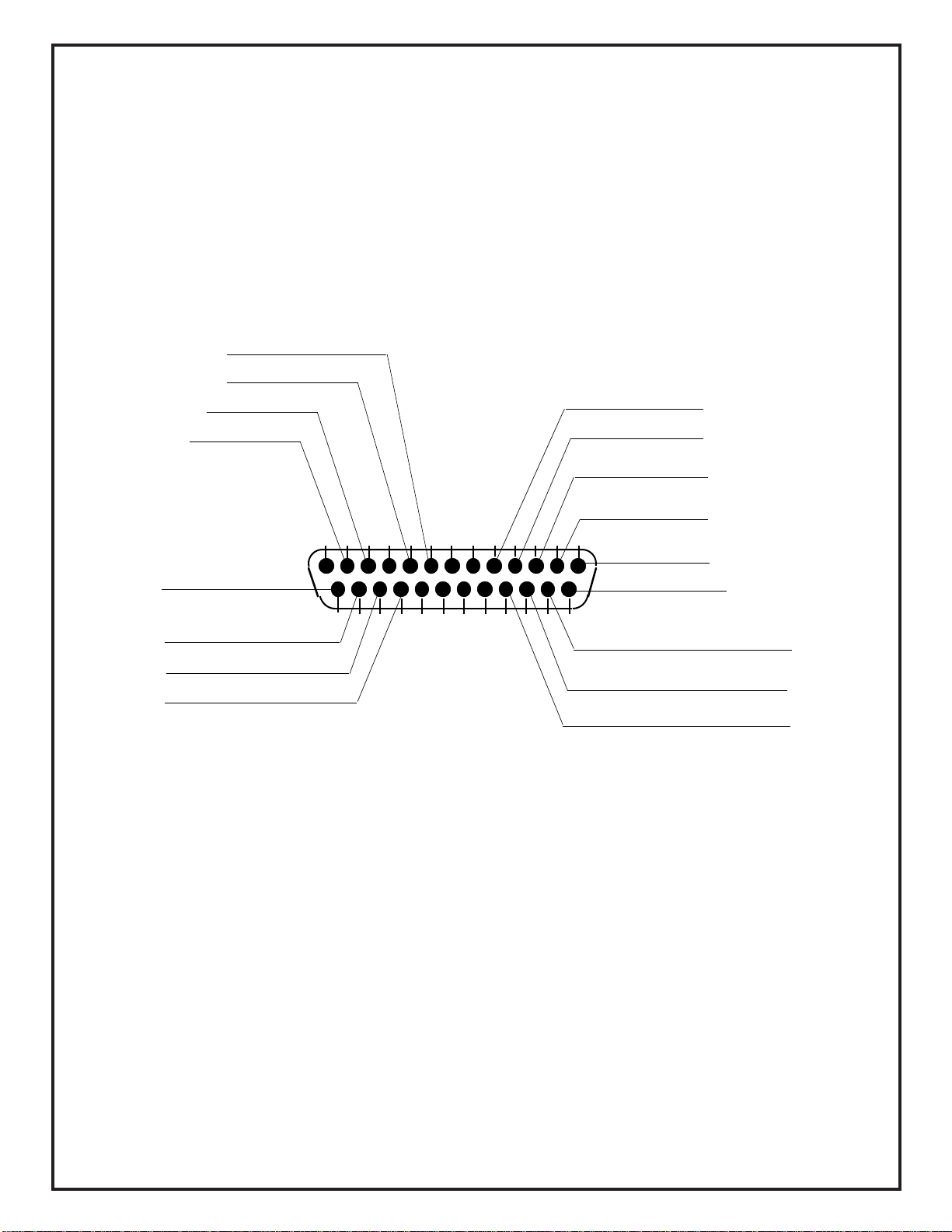
HF-2BB
Brown - 12VAC
Brown - 12VAC
Blue - Ground
Yellow - Telco
Yellow - Telco
White - Call Btn
White - Call Btn
12345678910111213
Black - Speaker
Red - Speaker
1415161718
19202122232425
Violet - Relay(primary)
Violet - Relay(primary)
Orange - Relay(secodary)
Orange - Relay(secodary)
Black - LED
Red - LED
Green - Mic
Gray - Mic
HF-2 KIT Wiring

Page 12
HF-2BB
Table of contents
Other Trigon Electronics Emergency Phone manuals

Popular Emergency Phone manuals by other brands


Baldwin Boxall
Baldwin Boxall C2CFPE installation instructions

iSysmart
iSysmart SGZ308 user manual

Viking
Viking 1600A Series Technical practice

Viking
Viking E-1600A-BLT-EWP Technical practice

Care Messenger
Care Messenger Emergency Phone Quick start user guide

Rath
Rath 2100-ELL2 Installation & operation manual


