Trimax Solar TMX-MH7-120A User manual

1 ANLEITUNG 04_21
INSTALLATION AND OPERATING
INSTRUCTIONS
TRIMAX Solar GmbH
Leitzstraße 45
70469 Stuttgart
GERMANY
Tel : +49 711 490 66 278
Mail : info@trimax-solar.com
Web : trimax-solar.com

2 ANLEITUNG 04_21
CONTENT
PRELIMINARY REMARKS.........................................................................................................................................................................3
PACKAGING......................................................................................................................................................................................................3
Recommended unpacking method.................................................................................................................................................4
Horizontally packed modules............................................................................................................................................................4
Vertically packed modules..................................................................................................................................................................5
PRODUCT LABELING...................................................................................................................................................................................6
Label.................................................................................................................................................................................................................6
Serial Number............................................................................................................................................................................................6
SAFETY................................................................................................................................................................................................................6
General safety instructions...............................................................................................................................................................6
Fire protection...........................................................................................................................................................................................6
Mechanical installation........................................................................................................................................................................7
Electrical installation............................................................................................................................................................................8
PLANNING AND INSTALLATION..........................................................................................................................................................9
Intended use................................................................................................................................................................................................9
Shading...........................................................................................................................................................................................................9
Tilt Angle.....................................................................................................................................................................................................10
Glare behavior / Glare assessment.............................................................................................................................................10
Bifacial Modules......................................................................................................................................................................................10
Electrical design.....................................................................................................................................................................................10
System dimensioning.......................................................................................................................................................................11
Connectors............................................................................................................................................................................................12
Cable..........................................................................................................................................................................................................12
Grounding/ (Potential equalization)......................................................................................................................................13
Design substructure............................................................................................................................................................................13
Load capacity............................................................................................................................................................................................13
Mounting with screws...................................................................................................................................................................14
Mounting with clamping systems...........................................................................................................................................15
Mounting with insertion systems...........................................................................................................................................16
MAINTENANCE............................................................................................................................................................................................18
Cleaning.......................................................................................................................................................................................................18
Module at end of life.............................................................................................................................................................................19
DISCLAIMER...................................................................................................................................................................................................19
List of Figures:........................................................................................................................................................................................20
List of Tables:...........................................................................................................................................................................................20

3 ANLEITUNG 04_21
PRELIMINARY REMARKS
Thank you for choosing TRIMAX PV modules. This manual provides you with information to ensure that your
PV system generates optimal yields over its entire life cycle. This manual is intended for professionals
involved in the design, installation and commissioning of photovoltaic systems.
TRIMAX Solar produces high quality and reliable photovoltaic modules according to international standards
(ISO 9001 : 2015, ISO 14001 : 2015, ISO 45001 : 2018). TRIMAX Solar HALF-CUT PERC modules are certified
according to IEC 61730 and IEC 61215 and have also undergone salt spray and ammonia corrosion testing.
The 100% PID-free solar cells reliably provide stable yields throughout the warranty period and beyond.
Before installing the solar system, check with your local authorities and utility companies for applicable
guidelines and approval requirements.
Observe all necessary safety regulations during design and installation. This is the responsibility of the
installer of the system.
Keep the manual for the entire service life of the solar modules and ensure that this manual is accessible to
the operator at all times.
Pass the manual on to any subsequent owner or user of the solar modules.
We reserve the right to make changes to the product, specifications or instructions without prior notice.
Failure to do so may result in serious injury and damage and/or void the limited warranty and
guarantee.
PACKAGING
•Do not exceed the maximum stacking capacity of 2 pallets (standard packaging for shipping).
•Place the pallets only on firm and horizontal levels to prevent them from toppling over.
•Upon receipt, look for visible damage to the packaging and the product itself.
•Check the order information and the product nameplate to ensure that the products match the type
ordered.
•If you notice any problems, contact the shipping company and/or your supplier as soon as possible
before you start installing the product.
•Store the pallets in a ventilated, dry place until installation.
•Do not stack individual modules without protection to avoid scratching the glass and frame.
•Do not unpack the pallets in rain or snow.
•Do not pull the module out of the packaging by the cables or junction box.
•Removal of the modules from the packaging must be done by two people.
•Use a stand for removal to avoid damage caused by falling over.
4 ANLEITUNG 04_21
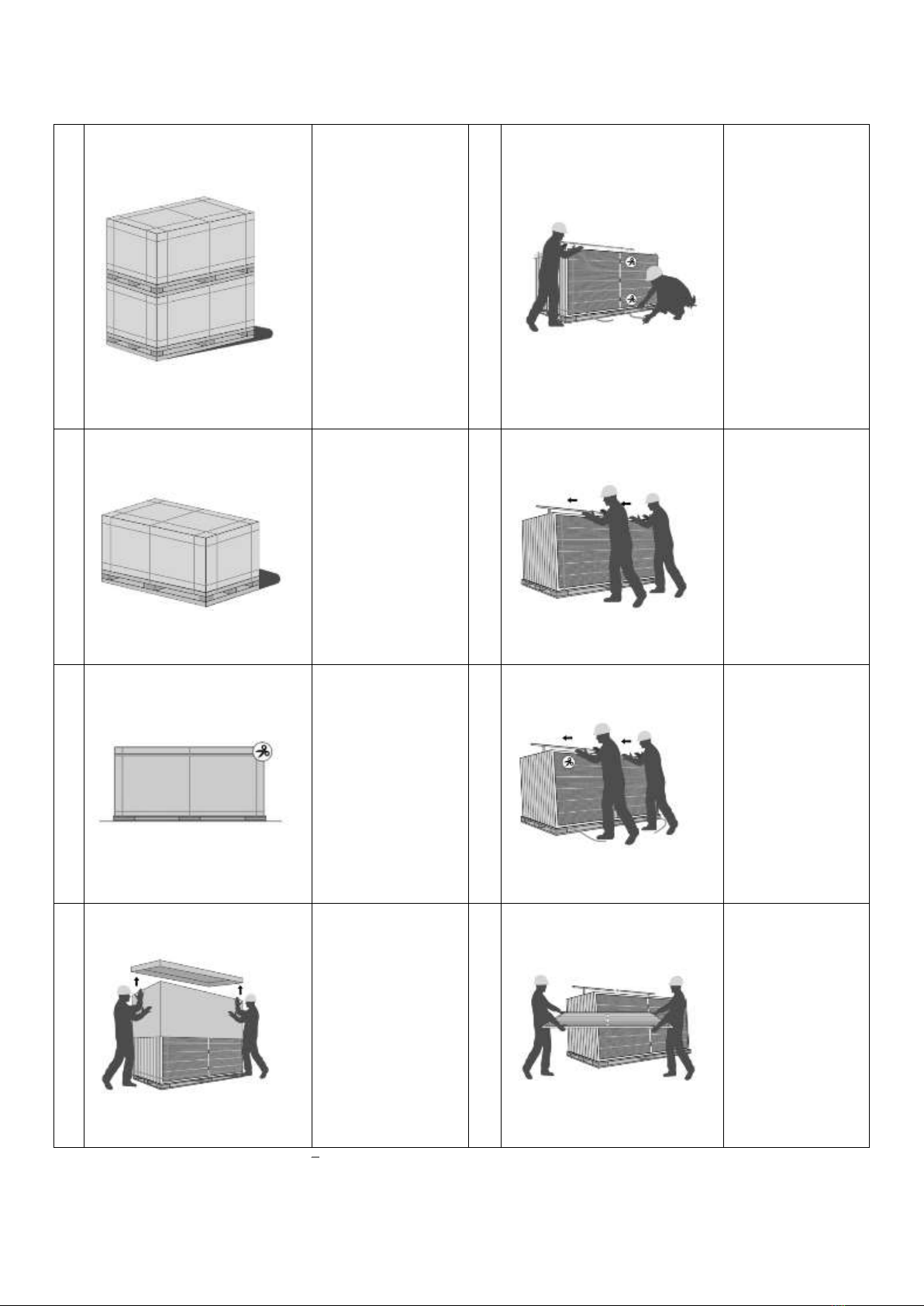
Recommended unpacking method
Horizontally packed modules
1.
Remove the packing
film.
5.
Cut and remove
only the horizontal
packing tapes.
2.
Place the pallets one
by one.
6.
Carefully press the
stack against a
stand.
(Not included!)
3.
Remove the outer
packing tapes.
7.
Cut the remaining
packing tapes.
4.
Remove the cover
and the outer
carton.
8.
Remove the
modules one by
one.
Table 1: Recommended unpacking method horizontally packed modules

5 ANLEITUNG 04_21
Vertically packed modules
1.
Remove the
packing film.
5.
Cut and remove
only the
horizontal packing
tapes.
2.
Remove the lid
and detach the
outer carton.
6.
Carefully press
the stack against
a stand.
(Not included!)
3.
Remove the
outer carton.
7.
Cut the remaining
packing tapes.
4.
Place the stand
on the glass
side of the
modules.
8.
Remove the
modules one after
the other. (Min. 2
persons)
Table 2: Recommended unpacking method - vertically packed modules

6 ANLEITUNG 04_21
PRODUCT LABELING
Each module can be identified by the following information:
Label
The nameplate is locatedon the back of the
module. In accordance with the guidelines of
EN 50380, it provides information about the
most important parameters of the module:
Figure 1: Label
Serial Number
Each individual module is identified by a unique serial number/barcode. The serial number/barcode are
permanently embedded in the laminate under the front glass of the module and are visible from the front of
the module.
SAFETY
General safety instructions
The design and installation of photovoltaic solar systems requires special skills and knowledge. Proper
implementation is the responsibility of the system designer and installer.
TRIMAX Solar PV modules may only be installed in compliance with all locally and nationally applicable
standards, rules and regulations. Check and follow all safety instructions, including those given by other
component suppliers.
Please contact our Technical Service if you have any questions about the instructions.
Fire protection
TRIMAX Solar PV modules have been tested in accordance with the provisions of the IEC EN 61730 directive
with application class A.
The fire safety has been evaluated with class C.
Please note the building code requirements. In Germany, it is the Landesbauordnung in your state. The roof
must be covered with a suitable fire-resistant material.
The installation of PV systems on a roof can affect the fire safety of a building. Compared to other technical
installations, they do not pose a particularly increased fire risk.
However, improper installations can lead to a hazard and fire. In particular, defects in current-conducting
components of the PV system can lead to the formation of electric arcs.
For this, please refer to VDE-AR-E 2100-712. This VDE application rule applies to the planning and installation
of low-voltage systems for photovoltaic (PV) power supply systems on or on buildings together with the
requirements of DIN VDE 0100-712.
7 ANLEITUNG 04_21
This VDE application rule contains supplementary recommendations to mitigate the likelihood of electric
shock to emergency personnel in case of fire (or similar) resulting from the fact that PV modules can produce
voltage when exposed to light, even if the AC side is disconnected.
•In order to inform firefighters that there is a PV system on the roof of the house, for example, it is
recommended that a photovoltaic system fire sign be placed on the side of the building where the
main access road is located. By having a PV system sign immediately visible, firefighters will have
advance notice of potential hazards that may be posed by the PV system in the event of a fire.
•Create sufficiently detailed documentation of the PV system ,to support a hazard-free execution of the
extinguishing process. Ensure that the system documentation is accessible to the fire department in
the event of a fire.
Safety distances for an extinguishing process in PV systems (according to DIN VDE 0132)
Low voltage High voltage
Spray jet: 1 meter 5 meters
Full jet: 5 meters 10 meters
•Do not install modules near open fire or flammable and explosive gases/substances.
•Only use plugs and sockets of the same manufacturer and type.
•Only use devices, plugs, cables and support frames that are suitable for use in a solar power system.
•Use temperature and UV resistant materials.
Mechanical installation
General notes
Always use constructions and materials that have been specially developed and certified for the installation of
photovoltaic modules. Always follow the instructions and safety precautions of the mounting system
manufacturer.
•Do not remove any components, such as plugs or cables, or attached nameplates.
•Do not apply paint or glue to the top of the module.
•Do not concentrate artificial sunlight on the solar module.
•Do not disassemble, drill or modify the frame or other parts of the PV module.
Safety instructions
•Do not install in high winds and prevent objects from falling from the roof.
•Secure the work area so that no one on or under the roof can be injured.
•When installing a module on a roof or building, make sure it is securely fastened.
•Avoid subjecting the frame to lateral tension and compression forces, as this could damage the glass.
•Do not bend the module frame.
•Do not damage the frame.
•Do not place the module down hard.
•Do not drop any objects on the module.
•Do not place heavy objects on the module.

8 ANLEITUNG 04_21
•Do not step on the module.
•Make sure that the drainage holes of the PV module are not blocked.
•Roof penetrations must be properly sealed.
•Ensure that cables or plugs are not trapped between the module and the substructure.
Electrical installation
General notes
The electrical connection must be carried out by a competent, authorized person/company. The electrical
installation of the PV system must be carried out in accordance with the respective national electrical
regulations or the applicable national regulations.
Safety instructions
•Exercise extreme caution during all work on the wiring.
•Observe the safety instructions for all other components used in the PV system.
•Do not wear metal rings, watch bands, ear, nose or lip rings, or other metal objects during installation
or troubleshooting of photovoltaic systems.
•Do not install solar modules or wiring with wet male and/or female connectors.
•A single module can generate DC voltages in excess of 30 V when exposed to light of any intensity.
Contact with a DC voltage of 30 V or more is potentially hazardous. Connecting modules in series or
parallel increases the voltage or electrical current.
•During installation, completely cover the module with a dark, opaque material to prevent current
generation.
•Do not install/operate damaged modules, as contact with the surface of the module or frame may
cause electric shock.
•Do not attempt to repair a module with broken glass or defective back panel.
•Do not disconnect modules under load to avoid electrical arcing. Contact with electrically active parts
of the modules, can cause burns, sparks and fatal shock, whether the module is connected or not.
•Do not use the junction box or cables as a handle.
•Do not use lubricant on the connectors.
•Do not remove the rubber rings on the junction box or connectors.
•Do not immerse modules or connectors in liquid.
•Do not insert electrically conductive objects into the plugs and/or sockets.
•Do not short-circuit the solar module cables under any circumstances.
•Ensure correct polarity of the cables.
•Only use or connect plugs and sockets of the same manufacturer and type.
•When connecting the plugs, make sure that they are securely connected.
•Lay cables carefully and protect them from the weather.
•Avoid cable damage due to sharp edges.
•Avoid cable damage caused by cable ties that are too tight.
•Do not fall below the smallest bending radius of the cables.
•Avoid tensile loads, especially on junction boxes and plug connections.
The cross-sectional area of the cable is 4mm2 or 12AWG. The smallest bending radius of the cables must not
be less than 43mm. Cable damage caused by excessive bending or by the cable management system is not
covered by the warranty.

9 ANLEITUNG 04_21
PLANNING AND INSTALLATION
Intended use
•TRIMAX PV modules are suitable for outdoor operation.
•Ambient temperature range: -40°C to +40°C
•Operating temperature range: -40°C to +85°.
•Humidity: 100% and rain
•Mechanical load capacity: snow load: 5400Pa wind load: 2400Pa
•< 2000m altitude sea level
•Do not expose the module to external light sources.
•There is a risk of corrosion if the module is exposed to salt (e.g. near the sea) or sulfur sources. The
modules have passed the salt spray test according to IEC61701, but galvanic corrosion may occur
between the aluminum frame of the modules and the mounting or grounding elements if these
elements are made of different metals. The modules can be installed in coastal locations <500m, but
the components should be protected from corrosion.
•The module should not be exposed to unusual chemical stresses.
•Ensure that the modules are not subjected to wind or snow loads that exceed the maximum allowable
loads.
•In regions with heavy snowfall, select the height of the mounting structure so that the lowest edge of
the module is not covered by snow and cannot beshaded by plants or trees or soiled by soil.
•Lightning protection is recommended for PV systems that are to be installed in locations with a high
probability of lightning strikes.
Shading
The modules should not be shaded at any time. Shading leads to a
lower power output. Furthermore, systemic shading can lead to
accelerated aging and damage to the module and failure of the
system. Perform a shading analysis. Shading objects such as trees
or houses can have a significant impact on the yield prediction.
Ensure sufficient row spacing for ground-mountedsystems to
avoid self-shadowing. Observe and avoid close shading by
chimneys, dormers, antenna tubes, lightning protection equipment
or overhead cables.
Consider the internal bypass diode configuration of the PV module
when selecting the orientation to ensure optimal electrical
performance against possible shading of the module.
In case of shading or soiling, in addition to the Schotky diodes, the
parallel connection of the half cells has the advantage that current
continues to flow through the unaffected string and thus 50% of
the original power still remains, but systemic shading should be
avoided to prevent permanent stress on the bypass diodes.
•Please do not attempt to open the junction box to replace
the diode.
Figure 2: Circuit Diagram 108 CELLS- HALF-
CUT-PERC

10 ANLEITUNG 04_21
Tilt Angle
PV modules should be installed in a location where they can receive the maximum amount of sunlight
throughout the year. In the Northern Hemisphere, the modules should face south, and in the Southern
Hemisphere, they should face north. As a rule of thumb, the tilt angle should be approximately equal to the
latitude of the project site and point toward the equator.
PV modules connected in series should be installed in the same orientation and with the same tilt angle. The
greatest power is generated when direct sunlight falls on the PV modules.
Dust and dirt accumulating on the surface of the modules can affect performance. TRIMAX Solar
recommends that modules be installed with a tilt angle of at least 15 degrees so that dust or dirt can be
washed off more easily by rain.
Figure 3: Tilt Angle
Table 3: Tilt Angle
Latitude
Tilt angle
0°~15°
15°
15°~25°
The same latitude
25°~30°
Same latitude +5°
30°~35°
Same latitude +10°
35°~40°
Same latitude +15°
40°+
Same latitude +20°
Glare behavior / Glare assessment
Under certain circumstances (e.g. nature reserves, traffic routes, airports), it may be necessary to check the
glare behavior of the PV power plant. Factors for the strength of the reflection include the position of the sun,
module orientation, coordinates of the installation site and the surface properties of the solar module.
Contact a professional provider for a glare assessment. TRIMAX Solar high performance PV modules are
coated with an ARC (Anti Reflective Coating). The glass coating with nano technology ensures that less light
is reflected and more light reaches the solar cells.
Bifacial Modules
TRIMAX Solar high power PV modules are equipped with bifacial PERC cells.PERC stands for Passivated
Emitter Rear Cell. The structure of the PERC cell essentially allows for improved light output at the rear of
the cell, which in turn increases electron yield. The bifaciality (the ratio of front and rear output under the
same conditions) can reach 65% ± 5%. The bifacial extra yield depends mainly on the system design, especially
the row and ground spacing, the angle and the reflectivity of the ground (albedo). Additional yields between 5
and 15% are possible. The reflectance varies depending on the soil resulting in different power generation. The
irradiance reflected to the back of the bifacial glass/film solar modules must not exceed 300 W/m2.
Electrical design
Maximum system voltage (Umax): 1000V or 1500V depending on product type.
Please check the nameplate and data sheet accordingly. For further technical data, please refer to the
respective data sheets - available online at www.trimax-solar.com.
•To avoid power loss or damage to the PV system, use only modules of the same type and
power within the same circuit.
•Protect the solar modules from overvoltage, e.g. voltage peaks from battery charging,
generators, etc.
•Only use plugs of the same manufacturer and type for cable extensions.
11 ANLEITUNG 04_21
System dimensioning
Under intended conditions, it is likely that a PV module will experience conditions which are likely to exist a
higher current and/or voltage is generated than specified for standard test conditions. To determine the
voltage ratings of components, current ratings of conductors, ratings of controls (e.g., inverters) that are
connected to the output of PV modules, the values of Isc and Voc indicated on the PV module shouldbe
compared with values of Isc and Voc should be multiplied by a factor of 1.25.
The reflection of snow or water can amplify sunlight, increasing current and power. In addition, colder
temperatures can significantly increase power. The safety factor of 1.25 for the lowest voltage rating of
components can be modified during the design of a system according to the minimum temperature of the PV
system site and the temperature coefficient for Voc. The Isc can be modified based on maximum temperature,
irradiance and orientation of the module. For this purpose, a complete simulation for the specific site with
long-term weather data is required.
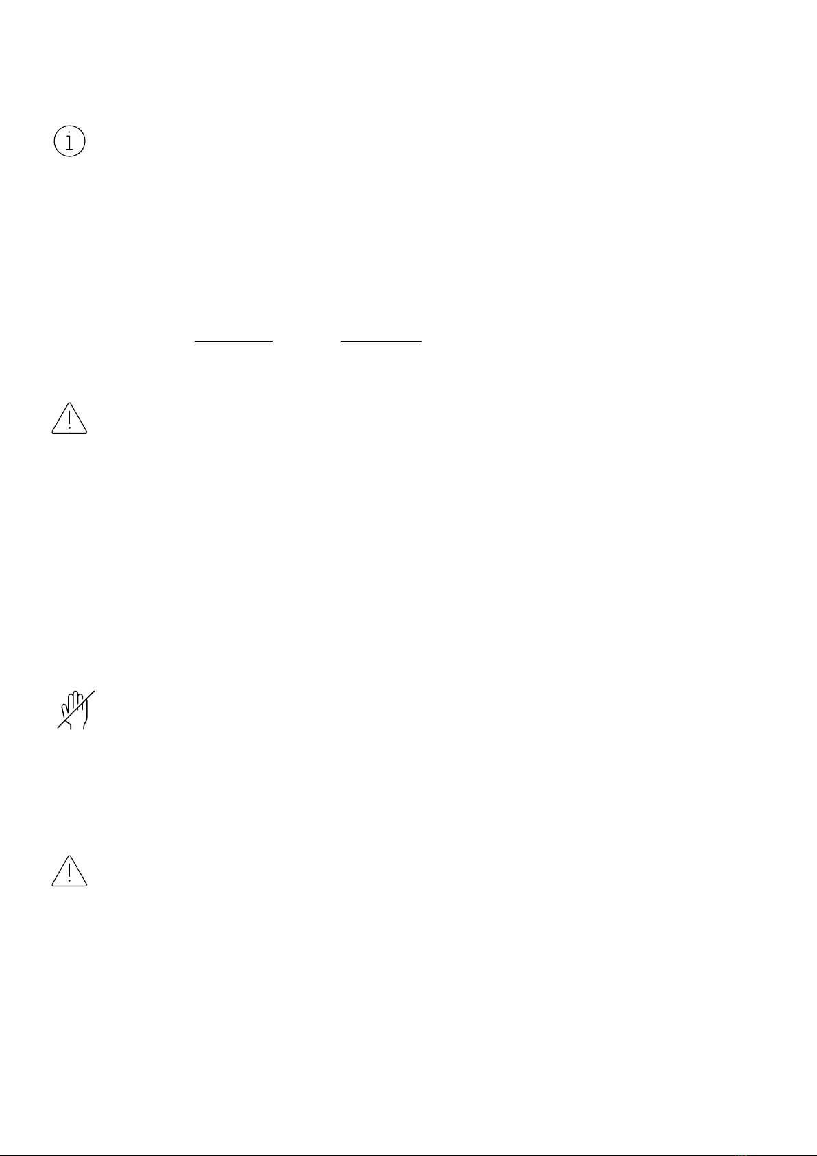
Maximum number of interconnected PV modules
When modules are connected in series, the total voltage is equal to the sum of the individual voltages. For
applications that require high currents, photovoltaic modules can be connected in parallel. The total current
is equal to the sum of the individual currents.
Module max = Vsys / Voc x 1.25
Maximum number of modules = Modulmax
Maximum system voltage = Vsys
Open circuit voltage = Voc
Circuit Diagram - Series/ parallel connection
Figure 4: Series Connection
Figure 5: Parallel Connection
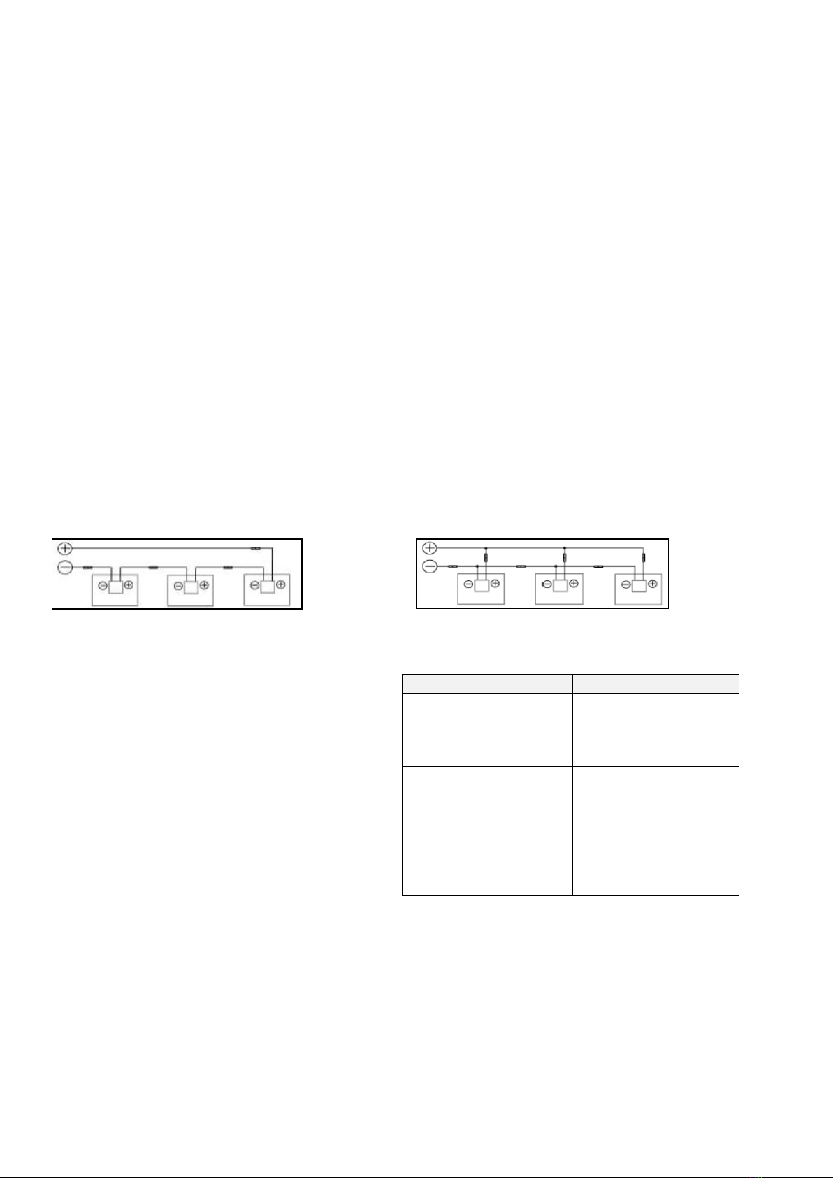
Overcurrent protection device
An appropriately rated overcurrent protection
device should be used if the reverse current
could exceed the value of the maximum fuse
protection of the modules.
An overcurrent protection device is required for
each series string if more than two series
strings are connected in parallel.
Type
Max. reverse current
TMXMH7-120A
TMXMH7-120B
TMXMH7-132A
TMXMH7-144A
20A
TMXMH8-108A
TMXMH8-120A
TMXMH8-132A
TMXMH8-144A
25A
TMXMH9-108A
TMXMH9-120A
TMXMH9-132A
30A
Table 4: Maximum reverse current
12 ANLEITUNG 04_21
Connectors
For the electrical connection of the system, the cables end with connectors from Stäubli MC4 Evo2 (positive
[+] and negative [-]). Further certified manufacturers and possible connector types can be found in the
following overview:
Type
Manufacturer
System Voltage
Rated
Current
Temperature
Rating
PV-KST4-EVO 2/xy-UR;
PV-KBT4-EVO 2/xy-UR
Stäubli Electrical Connectors AG
DC 1500V
45A
-40ºC to +85ºC
05-8
Zhejiang Renhe Photovoltaic Technology
Co.,Ltd
DC 1500V
30A
-40ºC to +85ºC
PV-CY03L
Zhejiang Chuangyuan Photovoltaic
Technology Co.,Ltd
DC 1500V
30A
-40ºC to +85ºC
RHC2xyzu
Zhejiang Renhe Photovoltaic Technology
Co.,Ltd
DC 1500V
35A
-40ºC to +85ºC
QC4.10-cds
QC Solar (Suzhou) Corparation.
DC 1500V
41A
-40ºC to +85ºC
PV-ZPJ030A
The 40th Institute of China Electronic
Technology Group Corporation
DC 1500V
38A
-40ºC to +85ºC
Cable
TRIMAX Solar PV modules are equipped with two pre-terminated, temperature and UV resistant cable leads
(Rated 1500V DC, -40°C to 90 °C). The cross section of the cable is 4mm2 or 12AWG. Outer diameter is
5mm to 7mm. The smallest bending radius of the cables must not be less than 43mm. Cable damage caused
by excessive bending or by the cable management system is not covered by the warranty.
When selecting the size of the cables connecting the module strings to the solar inverter, observe the
electrical parameters specified on the module data sheet. To avoid overheating of the cables and the
connectors, the cross-section of the cables and the capacity of the connectors must be selected according
to the maximum system short-circuit current. The PV cable must be at least 4 mm2. Only use cables that are
certified for use with PV systems.
Observe the requirements of DIN VDE 0100-520. The standard applies to the selection and installation of
cable and line systems. Cable and line installations are the totality of one and/or more cables or lines or
busbars and their fastening means as well as their mechanical protection, if applicable. The standard contains,
among other things, requirements for types of cable and line installations, selection and installation according
to environmental influences, cross-sections of conductors, voltage drop in consumer installations, electrical
connections, selection and installation to limit fires, proximity to other technical installations, selection and
installation with regard to maintenance including cleaning.
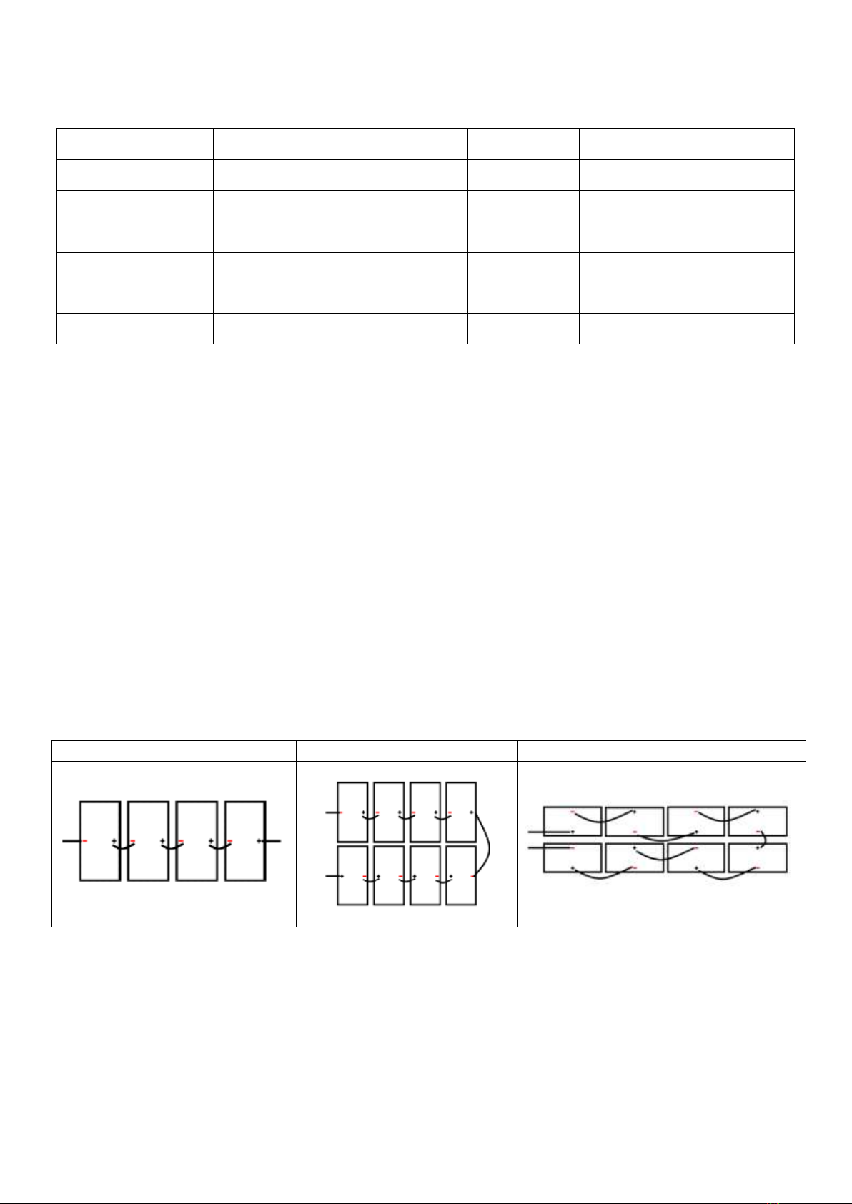
Wiring examples
Single row vertical installation
Two rows of vertical installation
Horizontal installation
Table 5: Connection of Modules

13 ANLEITUNG 04_21
Grounding/ (Potential equalization)
Please observe the requirements and standards of the respective national directives for equipotential
bonding. DIN VDE 0100-540 applies to grounding systems and protective conductors including protective
equipotential bonding conductors with the aim of fulfilling the safety of electrical systems.
TRIMAX Solar uses a frame made of anodized aluminum. Therefore, the modules should be connected to the
protective equipotential bonding to prevent electric shock.
Module frame and equipotential bonding must not be used as part of lightning protection. Have the lightning
protection planned and installed by qualified specialists. Avoid electrical corrosion by taking appropriate
measures.
Grounding methods:
The grounding conductor should be at least the
same size as the electrical conductors. Grounding
cables of not less than 4 mm² are recommended. The
frame has pre-drilled holes marked with a grounding
symbol.
Figure 6: Grounding Symbol
•The grounding holes may only be used for
grounding purposes and not for module
mounting.
Figure 7: Grounding
Additional third-party grounding devices:
TRIMAX PV modules can be grounded using third-party grounding devices. It is required that these devices
are certified for grounding solar modules and are installed according to the manufacturer's instructions.
Design substructure
•For rooftop systems, always make sure the roof structure is suitable before installing the modules on
a roof.
•Make sure that the modules do not overlap or exceed the size of the roof.
•Consider the thermal linear expansion of the frames: The recommended minimum distance between
two modules is 1 cm.
•For ground-mounted systems, the recommended minimum distance from the ground to the bottom
edge of the module is at least 50 cm.
•Provide adequate ventilation under/behind the modules to cool them. A minimum distance of 10 cm
between the roof level and the frame of the module is generally recommended.
•When planning the final arrangement of the modules, keep a suitable access area free to facilitate
maintenance and inspection work.
•Do not place the PV modules near air conditioning units or above ventilation outlets.
Load capacity
TRIMAX PV modules can be installed in both landscape and portrait format. Please refer to the load
specifications for the individual module types in the next sections. Please note that this may vary depending
on the mounting system and configuration. The specified values correspond to the design load according to
IEC 61215: 2016. The cyclic load test is carried out according to the standard with the 1.5 times higher test
load. The substructure should be made of durable, corrosion and UV resistant material. Make sure that the
installation method and the substructure can withstand the loading conditions.

14 ANLEITUNG 04_21
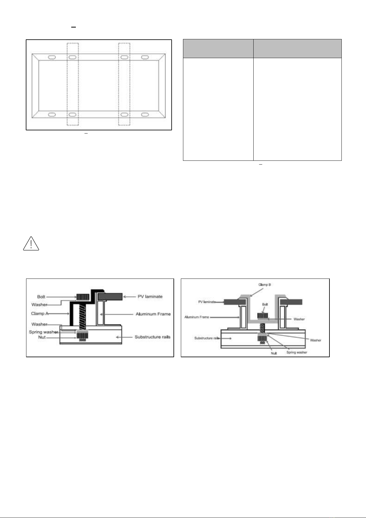
Mounting with screws
TRIMAX Solar - PV modules can be securely fastened to the mounting system (support rails) via the mounting
holes provided. 8 fixing holes are provided to optimize the load capacity of the module and to fix it to the
support structure. If increased wind or snow loads are expected, the additional fixing holes provided should be
used.
Recommended to use corrosion resistant stainless steel
screws.
1. screw - size and length: M8x16mm
2. washer - size: M8
3. spring washer - size: M8
4. nut - size: M8
Torque: 14 Nm - 20 Nm
Load capacity Screw outer mounting holes
Figure 9: Load Capacity Screw outer mounting holes
Module Type
Maximum mechanical load
TMX-MH8-144
Positive: 5400 Pa
Negative: 2400 Pa
TMX-MH9-132
TMX-MH9-120
TMX-MH9-108
Positive: 2400 Pa
Negative: 2400 Pa
Table 6: Approved load capacity Screw outer mounting holes
Figure 8: Mounting with screws
15 ANLEITUNG 04_21
Load capacity Screw inner mounting holes
Figure 10: Load capacity Screw inner mounting holes
Module Type
Maximum mechanical load
TMX-MH7-120
TMX-MH7-132
TMX-MH8-108
TMX-MH8-120
TMX-MH8-132
TMX-MH8-144
TMX-MH9-108
TMX-MH9-120
TMX-MH9-132
Positive: 5400 Pa
Negative: 2400 Pa
Table 7: Approved load capacity Screw inner mounting holes
Mounting with clamping systems
Mounting with clamp systems can be done on both sides of the module frame. Use at least 4 clamps per
module, two on both long sides or two on each short side of the module, depending on the orientation.
Depending on local wind and snow conditions, additional clamps may be required to ensure the module's load
capacity.
•Module clamps must not come into contact with the front glass or deform the frame.
•Take care to avoid shadows caused by module clamps.
Figure 11: End clamp
Figure 12: Center clamp

16 ANLEITUNG 04_21
Load capacity - Clamping Long side
Figure 13: Load capacity - Clamping long side
S = ¼L ± 50mm ( clamping position = S ; module length = L )
Module Type
Maximum mechanical load
TMX-MH7-120
TMX-MH7-132
TMX-MH7-144
TMX-MH8-108
TMX-MH8-120
TMX-MH8-132
TMX-MH8-144
TMX-MH9-108
TMX-MH9-120
TMX-MH9-132
Positive: 5400 Pa
Negative: 2400 Pa
Table 8: Approved load capacity Clamping long side
Load capacity - Clamping Short side
Figure 14: Load capacity - Clamping short side
H= ¼W ( clamp position = H ; module width = W )
Module Type
Maximum mechanical load
TMX-MH7-132
TMX-MH7-144
TMX-MH8-132
TMX-MH8-144
TMX-MH9-108
TMX-MH9-120
TMX-MH9-132
Positive: 1200 Pa
Negative: 1200 Pa
TMX-MH7-120
TMX-MH8-108
Positive: 1800 Pa
Negative: 1800 Pa
Table 9: Approved load capacity Clamping short side
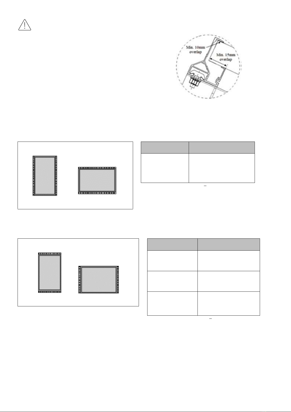
Mounting with insertion systems
TRIMAX PV modules are compatible with insertion systems from selected manufacturers. Installation
methods may vary and depend on the mounting structures. Follow the mounting guidelines recommended by
the mounting system supplier. Each module must be held securely along its entire length on two opposite
sides. Mount and tighten the slide-in profiles to the support structure according to the mounting guidelines
using the fasteners provided by the mounting system supplier. The system designer and installer are solely
responsible for load calculations and proper design of the support structure.
The TRIMAX Solar warranty may be void in cases where unsuitable insertion systems or improper installation
methods are found. Please observe the following recommendations when installing slide-in profiles:
17 ANLEITUNG 04_21
•Pay attention to the dimensions of the module and the
corresponding suitability of the insertion profile.
•Make sure that the insertion depth is sufficient:
oThe insertion profile must overlap the module
frame at the front by at least 10 mm.
oThe insertion profile must overlap the module
frame at the rear by at least 15 mm.
•The cells of the module must not be shaded.
•The front glass must not be touched by the insertion
profile.
Figure 15: Insertion system - Minimum overlap
Load capacity - support on the long sides
Figure 16: Load capacity - Insertion system - long side
Module Type
Maximum mechanical load
TMX-MH7-120
TMX-MH7-144
TMX-MH8-108
Positive: 4000 Pa
Negative: 2400 Pa
Table 10: Approved load capacity Insertion long side
Load capacity - support on the short sides
Figure 17: Load capacity - Insertion system - short side
Module Type
Maximum mechanical load
TMX-MH7-120
TMX-MH8-108
Positive: 2200 Pa
Negative: 2200 Pa
TMX-MH7-132
Positive: 1600 Pa
Negative: 1600 Pa
TMX-MH7-144
Positive: 1200 Pa
Negative: 1200 Pa
Table 11: Approved load capacity Insertion short side

18 ANLEITUNG 04_21
MAINTENANCE
Have any problems that occur investigated by a competent specialist. Repair work may only be carried out by
competent and appropriately trained personnel. Improper maintenance can result in fatal electric shocks
and/or burns.
DIN EN IEC 62446-2:2021-08 Photovoltaic (PV) systems - Requirements for testing, documentation and
maintenance - Part 2: Grid-connected systems - Maintenance of PV systems (IEC 62446-2:2020); German
version EN IEC 62446-2:2020
English title
Photovoltaic (PV) systems - Requirements for testing, documentation and maintenance - Part 2: Grid
connected systems - Maintenance of PV systems (IEC 62446-2:2020); German version EN IEC 62446-
2:2020
•Modules generate voltage when exposed to sunlight. Cover the front surface of the modules with an
opaque and non-scratching material when servicing.
•Use appropriate safety equipment (insulated tools, insulated gloves, etc.) when handling the modules.
•For any electrical maintenance, the PV system must first be switched off.
•Do not touch live parts or cables and plugs.
•Do not disconnect the grounding when performing maintenance on the system.
We recommend the following maintenance to ensure optimal performance of the module:
•Check electrical connections every six months to ensure they are clean, secure and undamaged.
•Check that mounting hardware, terminal screws, and grounding components are tight and not
affected by corrosion.
•Replacement modules must be of the same type as those being replaced.
•Follow the maintenance instructions for all components used in the system, such as support frames,
charge controllers, inverters, batteries, etc.
Cleaning
Dirt and dust can accumulate on the glass surface of the PV module over time, especially in low slope
installations. This can lead to an overall reduction in power output and also to deposits on the bottom edge of
the modules due to dirt accumulation. Under most weather conditions, normal precipitation is sufficient to
keep the glass surface of the PV module clean.
We recommend regular cleaning of the PV modules to ensure maximum power output, especially in regions
with high levels of dust in the air or low precipitation as follows:
•Clean the glass surface of the module as needed, taking into account that a lower slope requires a
higher cleaning frequency.
•Always use water and a soft sponge or cloth for cleaning.
•A mild, non-abrasive detergent may be used to remove stubborn dirt and soaking may be required.
•Water with a high mineral content is not recommended as it may leave residues on the module.
•Do not clean modules with broken glass or exposed wiring. This may result in general electrical failure
of the module or risk of electric shock.
19 ANLEITUNG 04_21
•To avoid possible thermal shock, clean the modules in the early morning hours when the module is still
cold. This is especially recommended in regions with hotter temperatures.
•In cold environments with snow, do not attempt to remove the frozen snow or ice from the module as
this may scratch the front glass. Only soft snow can be removed carefully with a soft brush.
•Do not use abrasive sponges or aggressive tools that could scratch the surface of the module; in no
case should the dirt be removed dry, as this would result in micro-scratches that could negatively
affect the module's performance.
•Do not use high-pressure cleaners.
•Do not use cleaners that are highly acidic or strongly alkaline. Cleaners containing hydrofluoric acid
(HF) and pure alcohol or pure acetone must not be used.
Module at end of life
Please hand in electrical equipment that is no longer required for disposal at the designated
collection points. For information on where to dispose of the equipment, please contact your local
authorities. The garbage can symbol on the TRIMAX product labels means that the equipment must
be disposed of as hazardous waste in accordance with local regulations.
WEEE Reg-No.: DE65803239
DISCLAIMER
The use of this manual and the conditions or methods of installation, operation, use and maintenance of the
product are beyond the control of TRIMAX Solar. TRIMAX Solar expressly disclaims liability for any loss,
damage or expense arising out of or in any way connected with the installation, operation, use or
maintenance. TRIMAX Solar GmbH assumes no responsibility for infringement of patents or other third party
rights that may result from the use of the PV product. No license is granted, by implication or otherwise,
under any patent or patent rights.

20 ANLEITUNG 04_21
List of Figures:
Figure 1: Label....................................................................................................................................................................................................6
Figure 2: Circuit Diagram 108 CELLS- HALF-CUT-PERC...............................................................................................................9
Figure 3: Tilt Angle.........................................................................................................................................................................................10
Figure 4: Series Connection.......................................................................................................................................................................11
Figure 5: Parallel Connection.....................................................................................................................................................................11
Figure 6: Grounding Symbol......................................................................................................................................................................13
Figure 7: Grounding.......................................................................................................................................................................................13
Figure 8: Mounting with screws.............................................................................................................................................................14
Figure 9: Load Capacity Screw outer mounting holes..............................................................................................................14
Figure 10: Load capacity Screw inner mounting holes..............................................................................................................15
Figure 11: End clamp......................................................................................................................................................................................15
Figure 12: Center clamp..............................................................................................................................................................................15
Figure 13: Load capacity - Clamping long side...................................................................................................................................16
Figure 14: Load capacity - Clamping short side................................................................................................................................16
Figure 15: Insertion system - Minimum overlap...............................................................................................................................17
Figure 16: Load capacity - Insertion system - long side................................................................................................................17
Figure 17: Load capacity - Insertion system - short side.............................................................................................................17
List of Tables:
Table 1: Recommended unpacking method horizontally packed modules...........................................................................4
Table 2: Recommended unpacking method - vertically packed modules................................................................................5
Table 3: Tilt Angle...........................................................................................................................................................................................10
Table 4: Maximum reverse current........................................................................................................................................................11
Table 5: Connection of Modules...............................................................................................................................................................12
Table 6: Approved load capacity Screw outer mounting holes.............................................................................................14
Table 7: Approved load capacity Screw inner mounting holes.............................................................................................15
Table 8: Approved load capacity Clamping long side..................................................................................................................16
Table 9: Approved load capacity Clamping short side...............................................................................................................16
Table 10: Approved load capacity Insertion long side.................................................................................................................17
Table 11: Approved load capacity Insertion short side...............................................................................................................17
TRIMAX Solar GmbH
Leitzstraße 45
70469 Stuttgart
GERMANY
Tel : +49 711 490 66 278
Mail : info@trimax-solar.com
Web : trimax-solar.com
This manual suits for next models
20
Table of contents
Popular Solar Panel manuals by other brands


Panasonic
Panasonic EverVolt EVPV HK Series General installation manual

SOLE
SOLE S150 installation manual

Daikin
Daikin EKSV21P installation manual

TSMC Solar
TSMC Solar TS-110C1 Installation and safety manual

Baxi
Baxi Solarflo Commissioning, maintenance & servicing guide

REC
REC REC235 Series installation manual


