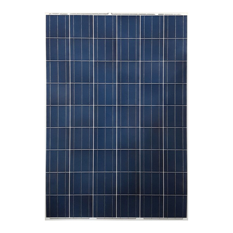
TSMC Solar TS-110C1 User guide

Installation and Safety Manual
Version 2.4, 12/1/2014
TS CIGS C1 Series
TS-110C1, TS-115C1, TS-120C1, TS-125C1, TS-130C1, TS-135C1, TS-140C1,
TS-145C1, TS-150C1, TS-155C1, TS-160C1, TS-165C1,
TS-130C1HV, TS-135C1HV, TS-140C1HV, TS-145C1HV, TS-150C1HV,
TS-155C1HV, TS-160C1HV

Revision History
Date
Version
Description
11/15/2012
1.0
Original version
5/8/2013
1.1
Add some statements about grounding hardware to comply UL 1703 Standard with its
revisions dated May 8, 2012. Moreover, the Electrical Ratings were changed for Models
TS-145C2, TS-150C2, and TS-155C2.
5/15/2013
2.0
Add a new Model TS-160C2 and deleted Models TS-125C2, TS-130C2, TS-135C2 and
TS-140C2 for UL certification.
10/1/2013
2.1
Update product specification in section 6A and add new models TS-165C2, TS-170C2 and
statements in Section 6, Installation and Operation
3/1/2014
2.2
Update product specification in section 6A and statement in Section 6D.
9/30/2014
2.3
Update 8.mounting methods and configurations
12/1/2014
2.4
Add a new model TS-165C1, TS-xxxC1HV(xxx=130~160) and WEEB grounding.
Moreover, the electrical ratings were changed for all models.

1. Introduction
With proper operation and maintenance, TSMC Solar modules will provide clean and renewable solar electricity
for years. This manual contains necessary installation, maintenance and safety information.
This Installation and Safety Manual will hereafter be referred to as “this manual”.
TSMC Solar Ltd., TSMC Solar Europe GmbH and TSMC Solar North America Inc. will all be referred to herein as
“TSMC Solar”.
TSMC Solar TS CIGS Series solar PV modules will hereafter be referred to as “TSMC Solar module(s)”or
“module(s)” or “the module(s).
Please retain this manual for your future reference.
2. Disclaimer of Liability
The use of this manual, the conditions and methods of installation as well as the operation, use, and maintenance
of TSMC Solar modules are beyond TSMC Solar’s control. Therefore, TSMC Solar assumes no responsibility and
expressly disclaims liability for loss, damage, injury or expense arising out of or in any way connected with such
installation, operation, use or maintenance of the modules. Furthermore, TSMC Solar assumes no responsibility
for any infringement of patents or other rights of third parties that may result from use of the modules, unless we
are automatically liable.
If you do not adhere to the instructions given in this manual, your rights under the TSMC Solar warranty may be
forfeited. Please check the warranty for the full details of your rights and obligations relating to your purchase and
use of TSMC Solar modules
3. General Information
This manual contains information regarding the installation and safe handling of TSMC Solar modules. All
instructions must be read and understood before attempting installation. If there are any questions, please
contact your sales representative or TSMC Solar for further information.
Installers must conform to all safety precautions in the manual when installing modules. Before installing, the
installer must become familiar with the mechanical and electrical requirements for PV systems.
Danger of death from electric shock!
Modules generate direct current (DC) electricity as soon as the front face is exposed to light.
Individual modules and especially connected systems can be an electrical hazard. Follow these general safety
and installation guidelines to avoid safety and electrical hazards.
WARNING

4. Warnings and Cautions
4.A Warning
All instructions must be read and understood before attempting to install, wire, operate, and/or maintain the
module. When modules are exposed to sunlight or other light sources, they generate DC electrical energy.
Contact with electrically active parts of the module such as terminals can result in burns, sparks, and lethal
shock whether the module is connected or disconnected.
Shock hazard increases as modules are connected in parallel, producing higher current, and as modules
are connected in series, producing higher voltage. The installer assumes the risk of all personal injury or
property damage that might occur during installation and handling of modules.
Do not disassemble, modify or remove parts of the module.
4.B Cautions
Use modules for their intended purpose ONLY.
Do not treat any portion of the module with paint or adhesives, to avoid damage to the module, inoperable
conditions, or reducing the module’s functionality.
5. Handling and Installation Safety
To avoid injury or damage:
Wear non-slip gloves.
Do not allow children or unauthorized persons near the installation site or module storage area.
Do not wear metallic rings, jewelry or devices while installing or troubleshooting photovoltaic systems.
Work only in dry conditions, with dry modules and tools.
Do not install the module where flammable gases or vapors are present.
Never leave a module unsupported or unsecured.
The back of the module must not be exposed to direct sunlight for extended periods of time during storage
or during the installation process to avoid the possibility of heat damage.
When disconnecting wires connected to a module that is exposed to sunlight, an electric arc may result.
Such arcs may cause burns, may start fires and may otherwise create problems. Be extremely careful!
Use only equipment, connectors, wiring and mounting structures suitable for use in a photovoltaic system.
Series connected modules should always be of uniform configuration and electrical specifications.
Cover the entire front surface of the modules with a dense, opaque material such as a cardboard box, when
working on a connected system cannot be avoided. Check for remaining voltage before starting, and
observe the relevant local safety regulations for such working conditions.
6. Installation and Operation
Photovoltaic systems must be installed by qualified and experienced personnel.
Install PV modules with a minimum spacing of 10mm between neighboring frames to allow for thermal
expansion.
Do not step on, or place objects on the module during or after installation. Although TSMC Solar modules

are quite rugged, the glass may be broken if it is dropped or hit by tools or other objects and the module will
no longer work properly. The module must not be exposed to concentrated sunlight, e.g. sunlight focused by
mirrors, lenses or other magnifiers.
The module frame is made of anodized aluminum, and therefore corrosion can occur if the module is placed
in a salt-water environment in contact with a rack made of another type of metal (Electrolytic Corrosion). If
required, stainless steel washers can be placed between the module frame and support structure to prevent
this type of corrosion.
Any module support structures that are to be used to support TSMC Solar modules must be wind rated and
approved for use by the appropriate local and civil codes prior to installation. In Canada, the installation
must be done in accordance with CSA C22.1, Safety Standard for Electrical installations, Canadian
Electrical Code, Part I.
Do not drill holes in the module frame
Any module without a frame (laminate) shall not be considered to comply with the requirements of UL 1703
unless the module is mounted with hardware that has been tested and evaluated with the module under this
standard or by a field Inspection certifying that the installed module complies with the requirements of UL
1703.
The module type has been qualified as “Application Class A”under IEC 61730-1.
Figure 1 Module Physical Specifications
All measurements in mm [inches]

6.A Module Product Specification
C1 Product
Type of Modules (Series) TS-110C1 TS-115C1 TS-120C1 TS-125C1 TS-130C1 TS-135C1 TS-140C1 TS-145C1 TS-150C1 TS-155C1 TS-160C1 TS-165C1
Maximum power (Pmax)110 115 120 125 130 135 140 145 150 155 160 165
Open-circuit voltage (Voc)62.0 62.3 62.6 63.0 63.3 63.6 63.9 64.2 64.5 64.8 65.2 65.5
Short-circuit current (Isc)3.61 3.61 3.61 3.61 3.61 3.61 3.61 3.61 3.61 3.61 3.61 3.61
Maximum power voltage (Vmpp)35.6 37.0 38.2 39.7 41.0 42.3 43.6 44.9 46.0 47.4 48.8 50.0
Maximum power current (Impp)3.09 3.11 3.14 3.15 3.17 3.19 3.21 3.23 3.26 3.27 3.28 3.30
Module efficiency 10.1% 10.6% 11.0% 11.5% 12.0% 12.4% 12.9% 13.4% 13.8% 14.3% 14.7% 15.2%
Certified by TUV SUD
Maximum system voltage (Vsys)
Maximum series fuse rating
Temperature coefficient of Pmax
Mechanical load
Dimension ininches (inch/mm)
Weight in lbs (kg)
Frame
38.5 (17.5)
Black Anodized Aluminum
TUV SUD
TUV SUD / UL
1000Vdc / 600Vdc(UL)
6A
-0.31%/℃
2400Pa (IEC) / 1695Pa (35lb/ft2, UL)
25.8 (656) x65.2 (1656)x 1.4 (35)
C1HV Product
Type of Modules (Series) TS-130C1HV TS-135C1HV TS-140C1HV TS-145C1HV TS-150C1HV TS-150C1HV TS-160C1HV
Maximum power (Pmax)130 135 140 145 150 155 160
Open-circuit voltage (Voc)63.3 63.6 63.9 64.2 64.5 64.8 65.2
Short-circuit current (Isc)3.61 3.61 3.61 3.61 3.61 3.61 3.61
Maximum power voltage (Vmpp)41.0 42.3 43.6 44.9 46.0 47.4 48.8
Maximum power current (Impp)3.17 3.19 3.21 3.23 3.26 3.27 3.28
Module efficiency 12.0% 12.4% 12.9% 13.4% 13.8% 14.3% 14.7%
Certified by
Maximum system voltage (Vsys)
Maximum series fuse rating
Temperature coefficient of Pmax
Mechanical load
Dimensionin inches (inch/mm)
Weight in lbs (kg)
Frame
UL
1000Vdc(UL)
6A
-0.31%/℃
1695Pa (35lb/ft2, UL)
25.8 (656) x65.2 (1656) x1.4 (35)
38.5 (17.5)
Black Anodized Aluminum
Measured at STC: Irradiance 1000W/m2 and cell temperature 25°C (77°F) AM=1.5 after factory light soaking.
All ratings +/- 10%, unless specified otherwise. Specifications are subject to change
Pmax Tolerance (UL) after IEC Light Soaking is +10%/-5%, before IEC Light Soaking Tolerance is +/-5%
Refer to datasheet for potential increases in Pmax, Voc and Vmpp after post-installation light soaking.
6.B Electrical Installation
“Under normal conditions, a photovoltaic module is likely to experience conditions that produce more current
and/or voltage than reported at standard test conditions. The requirements of the National Electrical Code (NEC)
in Article 690 shall be followed to address these increased outputs. In installations not under the requirements of
the NEC, the values of ISC and VOC marked on this module should be multiplied by a factor of 1.25 when
determining component voltage ratings, conductor ampacities, overcurrent device ratings, and size of controls
connected to the PV output.”
The multiplying factor at conditions of an irradiance of 1250 w/m2, AM1.5 spectrum, and a cell temperature of
-10°C (+14°F) for Voc is 1.25 and at cell temperature of 75°C (167°F) for Isc it is 1.25.
For field connections, use approved PV Copper wire only, minimum No. 14 AWG (2.5mm2) wires insulated for
minimum of 90°C, rated for wet conditions and resist to ultra violet radiation (where exposed)

6.C Electrical Wiring Method
To ensure proper system operation, correct cable connection polarity (Figure 2) must be observed when
connecting the modules to other modules. If not connected correctly, the bypass diode could be destroyed. If
modules are connected in series, the total voltage is equal to the sum of the individual module voltages. Only
connect modules or series combinations of modules with the same voltage. If modules are connected in parallel,
the total current is equal to the sum of individual module current.
Figure 2 Wiring Methods
6.D Correct Wiring Scheme
Match the polarities of cables and terminals when making the connections; failure to do so may result in
damage to the module.
Avoid immersion of cables and connectors in water and site them away from areas prone to water
collection. Ensure a minimum clearance of 10mm between the ground/roof surface and the
cables/connectors after installation.
Fix the cables/connectors to the module or mounting structure before commissioning the system.
Use the tool recommended by connector manufacturer when disconnection of connector is needed.
Example: open-end spanner PV-MS (Figure 3).
When routing cable, ensure forces on the cable do not create a visible deformation in the sealing portion of
the insulation. Do not create cable bends less than the 26mm minimum bending radius of our cables
(Figure 4)
In order to limit voltages induced by indirect lightning strikes, keep the area of all conductor loops to a
minimum
Series Wiring (voltage additive)
Parallel Wiring (current additive)

Figure 3 Example: Open-end spanner PV-MS Figure 4 Cable diagram
6.E Bypass diode
Model type
FR607G
GSR1010HD
Voltage rating
1000 (V)
1000 (V)
Current
8 (A)
10 (A)
Configuration
Single in J-box
Single in J-box
6.F Mechanical Installation
There are two mechanical installation methods, the clamp method and the bolt method. Mounting hardware
locations for both methods are illustrated in this section.
No matter which method is used, the modules are recommended to be mounted in portrait orientation (short side
parallel to ground) for best performance. If modules are mounted in landscape orientation (long side parallel to
ground), shading must be minimized as this orientation can significantly increase the impact of shading on
module performance. Please do not mount the module in landscape orientation with less than 10°tilt angle.
Clamp Method:
Modules mounted with clamps must have the center of the clamp positioned within the shaded clamp zones as
shown in Figure 5. This method enables a maximum mechanical loading of 2,400N/m2 (50PSF) (IEC),

.
Figure 5 Clamp Zone
Bolt Method:
The frame of each module has 8 x 6.6 mm [0.26”] mounting holes. Modules mounted by bolting the frame to
mounting structure must use the 4 mounting hole locations denoted “M1”in Figure 6. This method enables a
maximum mechanical loading of 2,400N/m2 (50PSF) (IEC) too, in a static state on the module surface.
The 4 mounting holes located further towards the short edge of the frame than the “M1” holes are reserved for
future product use and may NOT be used with current products.
All measurements in mm [inches]

Figure 6 Bolt Method Mounting Hole Locations
6.G Tilt Angle Selection
Module tilt angle is measured between the module and the ground as shown in Figure 7, with modules generating
the maximum power when they face sunlight directly (incident light perpendicular to module front surface).
The modules should be oriented to face south in the Northern Hemisphere and face north in the Southern
Hemisphere.
For installations where the modules are mounted on a permanent structure, they should be tilted so that the
energy production from the modules will be maximized on an annual basis. Generally this result will be achieved
when the tilt angle is near the value of the latitude of the mounting site. Use photovoltaic system simulation tools
or consult professional installers / system integrators to determine optimum tilt angle.
Tilt angles of at least 10°are recommended to reduce dirt or other substance accumulation. Please do not mount
the module in landscape orientation with less than 10°tilt angle.
Figure 7 Tilt Angle Definition
All measurements in mm [inches]

6.H Fire Class Rating
These modules have achieved aFire Resistance Rating of Class C. The fire rating of this module is valid only
when mounted in the manner specified in the mechanical mounting instructions as described in Section 8 of this
document, “Mounting Methods and Configurations”.
In rooftop installations, installed modules must have a standoff height between roof and module of more than 9cm
[3.54”] for airflow passage.
Note: During UL testing, the slope of the fire class test for this module is 5 in/ft.
Standoff Height
Module
Roof
Figure 8 Standoff Height
7. Grounding
A module with exposed conductive parts is considered to be in compliance with UL 1703 only when it is
electrically grounded in accordance with the instructions presented below and the requirements of the National
Electrical Code
The company installing the modules will be responsible for professional grounding of the modules. The
factory-provided aluminum frame must be grounded.
All grounding must be performed to be compliant with the latest regulations that are applicable for the jurisdiction
where the system is installed, e.g. the NEC (National Electric Code) in the United States.
If the building is already equipped with an exterior lightning protection system, the PV installation must be
integrated into the protection system against direct effects of lightning
There are eight 4.2mm [0.165”] grounding holes on the module frame, four on each of the module’s short sides.
The grounding holes are identified by a grounding mark (Figure 9) located next to each hole.
Figure 10 illustrates grounding the module. Ground wires must be connected to the module’s frame at one of the
grounding holes. The ground wire must not be smaller than No.14 AWG (2.5 mm²), and sized according local
regulations, e.g. the NEC (National Electric Code) in the United States.
The ground holes must be used with M4 screws. The length of these screws must not exceed 20 mm [0.78”] in
order to avoid contacting the back glass of the module. The screw length must not be less than 12 mm [0.47”].
The torque to be applied to the M4 screw is 3.0~4.0 N-m [22.1~26.6 in-lb].
The material of the frame is aluminum alloy. To avoid galvanic corrosion, all fasteners (nuts, bolts, washers,
9cm [3.54”]

screws, etc.) must be stainless steel unless otherwise specified.
Figure 9 Grounding Mark and Hole Dimensions
Figure 10 Grounding with Washers
WEEB grounding (Certified by UL only)
In addition, WEEB (Washer, Electrical Equipment Bond) grounding parts with UL 467 listing can be used with
TSMC Solar module. The WEEB parts must be installed in accordance to the manufacturers’ installation
instruction. The diagram below (Figure 11) shows how WEEB grounding parts are used with the end/middle
All measurements in mm [inches]

clamp in the installation. And the dimension of end/middle clamp for WEEB grounding parts have to follow our
proposed requirement that the clamp overlap the module frame by at least 5 mm, the clamp overlap length is at
least 38 mm and the fasteners torque of at least 10 ft-lbs (13.5N-m) is suggested.
Figure 11 Grounding with Clips
8. Mounting Methods and Configurations
The module is considered to be in compliance with UL 1703 only when the module is mounted in the manner
specified by the mounting instructions below
As introduced in section 6.F, there are two mechanical installation methods: Clamp and Bolt. Both methods of
mounting and configuration are explained below, respectively.
In all cases, PV modules are to be mounted over a fire resistant roof covering rated for the application.
Clamp Method
The module is secured to the mounting structure by clamping. A clamping solution requires a top clamp piece that
braces the front of the module frame, and a rail or bottom clamp piece that supports or clamps the bottom of the
module. The top clamp pieces hold the module securely at four points against rails or bottom clamps. Except for
modules at beginning and end of a row of modules, middle clamps can be used to hold two modules per clamp.
For the allowed location of each clamp on a PV module, see the clamp zone definition in section 6.F, Figure 4.
An example of top, bottom and middle clamp is shown in Table 1
When using clamping method, make sure the clamping overlap is positioned according to figure 12 and figure 13.
The module clamping method is shown in figure 14 and the clamping material should be anodized aluminum alloy.
Warranty may be void if inappropriate clamps or unsuitable clamping method are used.

Figure 12 Middle Clamp
Figure 13 End Clamp

Figure 14 Module Clamp Mounting Method

Bolt Method
The module can be mounted by bolting the frame to mounting structure. This method requires 4 sets of: M6 bolt,
M6 spring washer, M6 flat washer and M6 nut per module. There are eight mounting holes on the back side of
module, however only the 4 mounting hole locations denoted “M1” in Figure 6 can be used. These 4 holes are
offset from the short edge of module by 407.5mm [16.04”].
The installation method (Figure 15) requires that the spring washer be first placed on the bolt, followed by the
insertion of the bolt first through the module mounting hole in the aluminum frame then through the system rail.
Finally, after putting the flat washer and nut on the bolt, use torque of 6.1 N-m to screw the nut tight to complete
the installation. The bolt mounting method cross section is as shown in Figure 16.
SEE DETAIL A
DETAIL A
M6 BOLT
M6 SPRING WASHER
M6 FLAT WASHER
M6 NUT
Figure 15 Module Bolt Mounting Method
M6 BOLT
M6 SPRING WASHER
M6 FLAT WASHER
M6 NUT
Top edge of system rail
Figure 16 Bolt Mounting Method - Cross Section

Mechanical Components
Mounting mechanical means to be used in clamp or bolt methods are as below and as shown in Table 1:·
Screw/Bolt: M6 Stainless Steel
Nut: M6 Stainless Steel Flange Nut
Washer: M6 Stainless Flat Washer, M6 Spring Washer
Torque Value: 6.1 ~ 7 N-m [54.0~61.9 in-lb]
Clamps: Aluminum
50 [1.96"]
M6 NUT M6 WASHER TOP CLAMP
M6 FLANGE NUT BOTTOM CLAMP M6 BOLT (L: 55~65mm) [2.16"~2.56"]
MOUNTING STRUCTURE BEAM
60 [2.36"]
30 [1.18"]
50 [1.96"]
MIDDLE CLAMP
50 [1.96"]
M6 SPRING WASHER
Table 1 Mounting Method Mechanical Components
All measurements in mm [inches]

9. Serial Number Format and Definition
Every individual module has a unique serial number, with corresponding bar code.
Serial numbers have 11 digits. The meaning of the individual digits and groups of digits are as defined below.
Digit Position 1 2 3 4 5 6 7 8 9 10 11
Serial Number A 1 2 5 0 1 x x x x x
Fab Digits 2-6 encode productiondate
TSMC Solar internal use
In this example: May1, 2012
Serial number naming rules:
Digits Field name Naming rule
1st Fab Code “A” = Fab 1, “B” = Fab 2 etc.
2nd –3rd Year Last 2 digits of year, e.g. “11” = 2011, “12” = 2012
4th Month “1” – “9” = Jan – Sep respectively, “A” – “C” = Oct – Dec respectively
5th –6th Day “01” –“31” = 2 digit day, e.g. “15” = 15th of month
7th –11th Internal Use Defined for TSMC Solar internal use
Contact Information
Europe
TSMC Solar Europe GmbH
Am Kaiserkai 1
20457 Hamburg, Germany
Tel: +49 (0) 40/80 80 745 40
Fax:+49 (0) 40/80 80 749 20
North America
TSMC Solar North America Inc.
2595 Junction Avenue
San Jose, CA 95134 USA
Tel: +1 408 678 2816
Fax:+1 408 678 2800
Asia / International
TSMC Solar Ltd.
No. 5 Keya W. Rd, Daya District
Taichung, Taiwan 428-82 ROC
Tel: +886 4 2703 6688
Fax:+886 4 2569 3884
www.tsmc-solar.com
IM-TSC1-EN-01/15-01
This manual suits for next models
18
Table of contents
Popular Solar Panel manuals by other brands
Wetelux
Wetelux SL-SM-A-2 instruction manual

JIANGYIN TITANERGY
JIANGYIN TITANERGY TT-ADJUSTABLE TILT LEGS installation manual
Dwyer Instruments
Dwyer Instruments SPK quick start guide
Viking
Viking VSLT240-MH Operation and maintenance manual
Technaxx
Technaxx TX-241 user manual

Paua
Paua Air 300 Assembly instruction

