Trimod Besta Bxxx5 Series User manual

www.trimodbesta.com 1 │8 LTB011EN │2016.04
LTB011EN
Operating Instruction
Trimod Besta Level Switch – type B…5
for use in potentially explosive atmospheres acc. to IECEx scheme
Subject to technical modification
Bachofen AG | Ackerstrasse 42 | CH-8610 Uster | Switzerland
Phone +41 44 944 11 11 | Fax +41 44 944 12 33

www.trimodbesta.com 2 │8 LTB011EN │2016.04
Contents
2.
Conformity of standards..............................................................................................................................3
3.
Technical Data............................................................................................................................................3
4.
Installation and initial start-up.....................................................................................................................4
5.
Maintenance ...............................................................................................................................................5
6.
Replacement of the switch module.............................................................................................................6
7.
Fire protection.............................................................................................................................................6
8.
Disposal......................................................................................................................................................7
9.
IECEx - Certificate of Conformity................................................................................................................7
Legend
Information: Application hints and important information. To be followed for optimal function.
Attention:Requirements and prohibitions to prevent damages, especially to material and the environment.
Danger: Dangerous situation that can lead to injury and death if instructions are not followed.

www.trimodbesta.com 3 │8 LTB011EN │2016.04
1.
Safety Instructions
The operating manual must be read and understood before installation. If you are uncertain on any
point, please contact Bachofen AG, Switzerland.
The electrical connection may only be carried out by qualified personnel who have been authorised by
the operator.
All attached cables and cable bushings must comply with the requirements of IEC 60079-0 Appendix
A – explosion-proof cables and cable entries.
The supply voltage may only be applied after the cover has been closed. Please ensure that you
always observe the special regulations concerning work on explosion-proof devices and during work in
potentially explosive atmospheres at the operators site.
Every Trimod Besta level switch must be selected by qualified, trained personnel in accordance with
the specifications stipulated by the customer. These specifications must be kept by the operator in a
safe place, together with the operating instruction, the customer-specific designation and the type
number (see type plate). In the event of any deviation of the physical quantities (pressure,
temperature, density, etc.) from the original specification, the suitability of the level switch must be
checked again by qualified, trained personnel or by the manufacturer, with regard to the new
specifications.
If the device is mounted in a partition wall, which separates zones from one another, and if category 1
or 2 equipment is necessary, an equipotential bond must be made (contact resistance ≤MΩ) between
the metal housing of the level switch and the wall of the container.
The float and flange module must be included in the regular plant pressure tests.
Process vessels / float chambers must be brought to atmospheric pressure before work is carried
out and must be appropriately vented.
The devices may, under no circumstances, be used as a support aid or as a security fixture for
equipment structures or for persons.
When you are using a Trimod Besta level switch in a safety application according to
IEC 61508 and IEC 61511, the safety manual must be taken into consideration before
installing and commissioning the switch. The safety manual lists the restrictions and limitations of the
IEC 61508 certification of the Besta Trimod level switch. The safety manual can be downloaded from
http://www.trimodbesta.com/en/downloads/approvals/sil.html
2. Conformity of standards
Trimod Besta level switches type B…8 conform with the requirements of:
EN 60079-0, EN 60079-11, EN 60079-26
IEC 61508:2010 (Safety Integrity Level)
3. Technical Data
Ex-protection-data
Explosion protection Ex ia IIC T6 Ga/Gb
IECEx Certification of Conformity IECEx EPS 15.0038 X
Safety Integrity Level (SIL)
Type B…5 SIL 1 (SIL 3 capable)
Type BB…5 SIL 2 (SIL 3 capable)
Electrical connection
The electrical connection should be carried out in accordance with the regulations for explosion proof
devices.
Not suitable for the switching of motor loads and incandescent lamp loads. The device is not protected
against excess current.
www.trimodbesta.com 4 │8 LTB011EN │2016.04
Supply voltage For use in intrinsically-safe circuits only!
Maximum values I
i
= 0.5 A
C
i
, L
i
≈0 nF, 0 µH
The product of current and voltage should not exceed 0.12 VA, otherwise the gold contacts could be
permanently damaged.
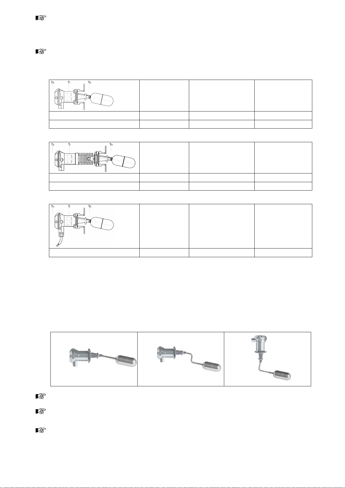
Special conditions for safe use
Level switch without heat exchanger
Limits
microswitch
T
i
Ambient temperature
(acc. to EN 60079-0
-20°C to 60°C)
T
A
Operating
temperature
T
0
B…5 -40°C to 150°C 0°C to 70°C 0°C to 330°C
DB…5 -40°C to 150°C -30°C to 120°C -30°C to 120°C
Level switch with heat exchanger for very high or very low operating temperatures
Limits
microswitch
T
i
Ambient temperature
(acc. to EN 60079-0
-20°C to 60°C)
T
A
Operating
temperature
T
0
HB…5, HBB…5 -40°C to 150°C 0°C to 135°C 0°C to 400°C
TDB…5, TDBB…5 -40°C to 150°C -10°C to 80°C -196°C to 270°C
Level switch for submersible application
Limits
microswitch
T
i
Ambient temperature
(acc. to EN 60079-0
-20°C to 60°C)
T
A
Operating
temperature
T
0
U…B…5, U…BB…5 -40°C to 150°C -30°C to 80°C -30°C to 80°C
The rated cross-section of the conductor to be considered here must be at least 0,5 mm².
Connection cables may not be bared for a distance of more than 3 mm from the terminal screw.
Wire end ferrules must always be used.
4. Installation and initial start-up
During installation, the correct operating position must be observed.
For side mounting, observe the “Top” arrow on the type plate.
The float must be able to move freely over the whole range of movement and must not be restricted by
the tanks walls or by fittings in the tank.
Installation positions that are subject to turbulence impair the function and should always be avoided.
www.trimodbesta.com 5 │8 LTB011EN │2016.04
Process connection flange - Industrial range
For switches in the industrial range with flanges according to DIN, ANSI, etc., the seals
1)
and
connecting studs
1)
that are used must correspond to the industry standard for material, pressure
class and type of seal and must be tightened to the corresponding tightening torques.
1)
not a component of the supply.
In case of uncertainty on any point, refer to the corresponding standard or consult the manufacturer.
Process connection flange - Standard range
For switches of the standard range PN 25 (360 psi), corresponding seals are supplied with the unit.
Minimum tightening torques and tightening sequence:
Flange
D
Seal
Stud
Carbon steel
Stud
Stainless steel
01 / 011
92 mm
Garlock Blue Gard 3000
Reinz Chemotherm
3)
18 Nm
2
)
22 Nm
2
)
2)
Data refer to lubricated studs
3)
High / low temperature application (graphite gasket)
Connecting
1. Loosen the cover screws, remove the protective plug from the cable entry and fit the cable gland.
2. Insert the cable and connect to the wires according to the connection diagram (see inside the
housing cover and instructions). All terminal connections are self-opening.
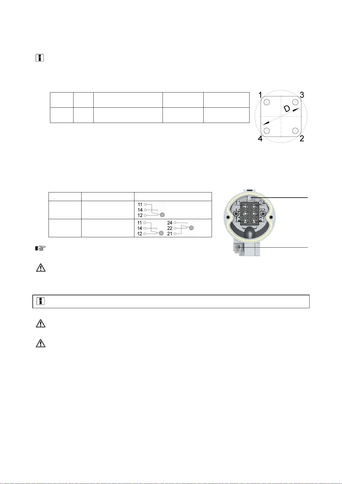
Connection diagram
Type
Function
Connection diagram
B…5 SPDT
BB…5 Dual SPDT
3. Connect grounding (inside housing) and equipotential bonding
screw (outside, beside cable entry)!
4. First close the cover and then apply the supply voltage!
5. Maintenance
Trimod Level switches must be periodically tested and cleaned, at least once annually.
Procedure:
1. Before opening the housing, disconnect the supply voltage; electric shocks can be life
threatening.
2. Process vessels / float chambers must be brought to atmospheric pressure before work is carried
out and must be appropriately vented. If necessary, lower the fill level. If the switch is mounted in
a chamber, close the corresponding shut-off valves and, depending on the requirement, empty or
vent the chamber.
3. Loosen the flange connection and remove the switch.
4. Check the float and mechanism for damage and contamination.
5. Remove deposits and metal particles by means of suitable and approved methods. Care must be
taken to ensure that no mechanical damage occurs as a result of the cleaning.
6. In the case of floats with protective bellows, the bellows must be removed before cleaning and
should be cleaned separately, both internally and externally.
7. Check the float and mechanism for complete deflection, as well as for smooth and unrestricted
operation.
Equipotential
bonding screw
Grounding

www.trimodbesta.com 6 │8 LTB011EN │2016.04
8. In the event that it becomes necessary to replace individual components, please note that only
original spare parts, split pins, float, switch module, etc. may be installed.
9. After completion of the cleaning / inspection work, the switch module must be checked for correct
function by means of an acoustic continuity tester or similar device with simultaneous deflection
of the float, followed by recording in the inspection log book.
10. In order to guarantee the absence of leaks between process vessel / float chamber, the flange
seal must be replaced after each dismantling.
11. After carrying out the inspection work, the device is re-fitted at the intended location.
6. Replacement of the switch module
Defective controller modules must be replaced with new, works-tested units. In order that the complete
type designation can be stamped on the type plate, the complete designation of the existing controller
must be specified at the time of ordering. If a complete identification of the controller is not possible,
then the manufacturer should be consulted before dispatching the complete device.
Example: Complete type number of the switch B5 01 04
Incomplete data of replacement switch module B5
Complete the type number with 01 04 ►B5 01 04
In the case of uncertainty on any point, please contact the local Trimod Besta agent or the
manufacturer.
Replacement of the switch module
The switch does not have to be removed from the process vessel in order to replace the switch
element.
1. Observe chapter 1 «Safety instructions».
2. Cut off power supply before opening enclosure cover! Be aware of the danger of hazardous
voltage!
3. Loosen 2 cover screws with screwdriver.
4. Check that terminals are not live.
5. Disconnect wires, including grounding and equipotential connection.
6. Loosen 2 Allan screws (Allan key 5 mm) on the side of the terminal block.
7. Unscrew switch module (together with intermediate temperature piece, for H… and TD… types)
from the flange module.
8. Make sure that the O-ring seals or flat gaskets fit properly.
9. Fit replacement module (together with intermediate temperature piece, for H… and TD… types)
and tighten 2 screws.
10. Re-connect wires including grounding- and equipotential bonding connection (see connection
diagram inside cover and attached switch operating instruction).
11. Energize power supply only when hinged cover is closed!
Follow the installation instruction LTI004X «Replacement of the switch module»
7. Fire protection
Trimod Besta level switches must be protected against external fires.

www.trimodbesta.com 7 │8 LTB011EN │2016.04
8. Disposal
Trimod Besta level switches are free of asbestos or otherwise hazardous materials (2011/65/EU - RoHS).
Disposal to be carried out according to environmental and local regulations.
9. IECEx - Certificate of Conformity
See http://iecex.com/

www.trimodbesta.com 8 │8 LTB011EN │2016.04
Subject to technical modification
Bachofen AG | Ackerstrasse 42 | CH-8610 Uster | Switzerland
Phone +41 44 944 11 11 | Fax +41 44 944 12 33
This manual suits for next models
9
Table of contents
Other Trimod Besta Switch manuals

Popular Switch manuals by other brands

Sun Oracle
Sun Oracle Sun Datacenter InfiniBand Switch 36 Hardware Security Guide

AVE
AVE 8PSWT specification

Micas
Micas M2-W6910-64C Hardware installation and reference guide

Siemens
Siemens RUGGEDCOM RX1500 user guide

NVT Phybridge
NVT Phybridge CLEER24 Quick install guide

HP
HP 6127XLG Blade Series Command reference


